Table of Contents
Advertisement
Quick Links
Setup - Operation
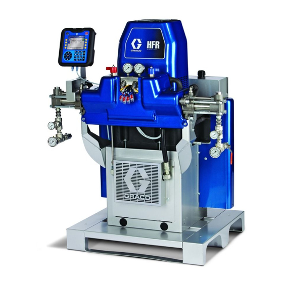
HFRL and HFRS
Hydraulic, Plural-Component, Fixed-Ratio Proportioner.
For pouring and dispensing laminates and silicones.
For professional use only. Not approved for use in explosive atmospheres or hazardous
locations.
Important Safety Instructions
Read all warnings and instructions in this
manual. Save these instructions.
See page 4 for model information and maximum
working pressure.
Silicone unit shown.
3A2175Z
EN
ti18208a
Advertisement
Table of Contents
Troubleshooting

Related Manuals for Graco HFRL


Summary of Contents for Graco HFRL
- Page 1 Setup - Operation HFRL and HFRS 3A2175Z Hydraulic, Plural-Component, Fixed-Ratio Proportioner. For pouring and dispensing laminates and silicones. For professional use only. Not approved for use in explosive atmospheres or hazardous locations. Important Safety Instructions Read all warnings and instructions in this manual.
-
Page 2: Table Of Contents
Appendix G- Temperature ....104 Typical HFRL System ..... . 17 Temperature Displayed and Actual Material Component Identification . -
Page 3: Related Manuals
3A2176 HFRL and HFRS Repair-Parts Pumpline Manuals 3A0019 Z-Series Chemical Pumps Instructions-Parts 3A0020 ™ Hydraulic Actuator Instructions-Parts Feed System Manuals for HFRL Systems 3A0235 Feed Supply Kits Instructions-Parts Dispense Valve Manuals 312185 MD2 Valve, Instructions-Parts Accessory Manuals 3A1149 HFR Discrete Gateway Module Kits Manual 3A1244 ™... -
Page 4: Models
Models Models HFR-Laminate (HFRL) HFRL models are designed for use with low viscosity, unheated urethane laminating adhesives at flow rates of up to 30 cc/sec (4 lb/min) @ 1500 psi (10 MPa, 103 bar). A Pump B Pump Required cpm@ Max Flow †... - Page 5 Models HFRL Models Part Number Description HFRL23 ★✖ HFR for Lamination, 400/3, 1.60:1, Part Number Description 80/50, Carbon Steel HFRL01 HFR for Lamination, 230/1, 1.00:1, HFRL24 ★✖ HFR for Lamination, 400/3, 1.63:1, 80/80, Carbon Steel 65/40, Carbon Steel HFRL02 HFR for Lamination, 230/1, 1.08:1, HFRL25 ★✖...
-
Page 6: Hfr-Silicone (Hfrs)
Models HFR-Silicone (HFRS) HFRS models are designed for use with high viscosity, unheated silicone adhesives at flow rates of up to 20 cc/sec (3 lb/min) @ 2500 psi (17 MPa, 172 bar). The equipment can be run at up to 20 cycles per minute continuous duty. - Page 7 Models HFRS Models Part Num- Description Part Num- HFRS23 HFR for Silicone, 230/1, 5.33:1, Car- Description bon Steel, 5/5 Feed HFRS01 HFR for Silicone, 230/1, 1:1, Carbon HFRS24 ★ HFR for Silicone, 400/3, 5.33:1, Car- Steel, 55/55 Feed, (10/10 pumps) bon Steel, 55/55 Feed HFRS02 HFR for Silicone, 230/1, 1:1, Carbon...
- Page 8 Models Part Num- Part Num- Description Description HFRS45 HFR for Silicone, 230/1, 10:1, Carbon HFRS67 HFR for Silicone, 400/3, 2:1, Stainless Steel, 55/55 Feed Steel, 55/5 Feed HFRS46 HFR for Silicone, 230/1, 10:1, Carbon HFRS68 ★✖ HFR for Silicone, 400/3, 2:1, Stainless Steel, 55/5 Feed Steel, 5/5 Feed HFRS47...
- Page 9 Models 400 V Power Requirements Part Num- Description • 400 V systems are intended for International volt- HFRS89 HFR for Silicone, 230/1, 10:1, Carbon age requirements. Not for voltage requirements in Steel, No Feed North America. HFRS90 ★✖ HFR for Silicone, 400/3, 10:1, Carbon •...
-
Page 10: Warnings
Warnings Warnings The following warnings are for the setup, use, grounding, maintenance, and repair of this equipment. The exclama- tion point symbol alerts you to a general warning and the hazard symbol refers to procedure-specific risk. Refer back to these warnings. Additional, product-specific warnings may be found throughout the body of this manual where applicable. - Page 11 Warnings WARNING FIRE AND EXPLOSION HAZARD Flammable fumes, such as solvent and paint fumes, in work area can ignite or explode. To help pre- vent fire and explosion: • Use equipment only in well ventilated area. • Eliminate all ignition sources; such as pilot lights, cigarettes, portable electric lamps, and plastic drop cloths (potential static arc).
- Page 12 Warnings WARNING EQUIPMENT MISUSE HAZARD Misuse can cause death or serious injury. • Do not operate the unit when fatigued or under the influence of drugs or alcohol. • Do not exceed the maximum working pressure or temperature rating of the lowest rated system component.
- Page 13 Warnings 3A2175Z...
-
Page 14: Important Two-Component Material Information
Important Two-Component Material Information Important Two-Component Material Information Isocyanate Conditions Moisture Sensitivity of Isocyanates Isocyanates (ISO) are catalysts used in two component foam and polyurea coatings. ISO will react with mois- Spraying or dispensing materials containing isocya- ture (such as humidity) to form small, hard, abrasive nates creates potentially harmful mists, vapors, and crystals, which become suspended in the fluid. -
Page 15: Changing Materials
The high volume material is typically the ISO and is located on the A (Red) side. Some material chemistries may have an ISO which is the low volume material. For HFRL Systems: The high volume material will always be the B (Blue) side.Typical Installation... -
Page 16: Typical Hfrs System
Typical HFRS System Typical HFRS System ti18208a . 1: HFR Silicone System Key: HFR Unit (Silicone) Dispense Gun Power Module Orifice Block B “Blue” Pump Orifice, 1/4” A ”Red” Pump Supply Unit, B Side Outlet Module Supply Unit, A Side B Hose Kit Supply Hose A Hose Kit... -
Page 17: Typical Hfrl System
Typical HFRL System Typical HFRL System ti18209a . 2: HFR Laminate System Key: AA HFR Unit (Laminate) AH Dispense Gun AB Power Module AJ Orifice Block AC B “Blue” Pump AK Orifice, 1/4” AD A “Red” Pump AL Inlet Assembly... -
Page 18: Component Identification
Component Identification Component Identification (Located on opposite side of machine) ti18210a . 3: Component Identification, shown with shrouds removed Key for F . 4. BS Grease Reservoir Bottle (Included on all HFLR) BT Pumpline Linear Sensor BA Advanced Display Module (see page 24) BU Motor Control Module, see page 22 BB Component A (Red) Pressure Relief Outlet BV Main Power Switch... - Page 19 Component Identification HFRS Material Inlet HFRL Material Inlet (3000 psi Max) (250 psi Max) ti18211a ti18212a Fluid Manifold (FM) Detail Rear View 24C352_313998_4e ti9880a1 . 4: Component Identification, shown with shrouds removed 3A2175Z...
- Page 20 Component Identification Main Power Switch Circuit Breakers Located on rear of machine. The circuit breakers are located on the panel assembly mounted directly behind the disconnect switch panel on the right side of the enclosure. For more information about items on the power distribution panel, see man- ual 3A2176 ti18213a The main power switch turns power ON...
-
Page 21: Hydraulic Power Pack
Component Identification Hydraulic Power Pack 24C352_313998_2g Key: DA 8 Gallon Hydraulic Oil Reservoir (see Accessories on DE Directional Valve page 136 for specifications) DF Motor Control Module (see page 22) DB Electric Motor DG Fan DC Dipstick (not shown, located at rear left of hydraulic tank) DH Filter DD Hydraulic Housing DJ Shroud (not shown, removed for clarity) -
Page 22: Motor Control Module (Mcm)
Component Identification Motor Control Module (MCM) For MCM location, see reference MA in F . 4 on NOTICE page 19. When installed, the end of the MCM with the If the Motor Control Module is replaced, the selec- power input connection (12) faces down and the end tor switch must be set prior to initial startup of the with the access cover (A) faces up. - Page 23 Component Identification Description Access Cover LEDs Warning Label 1A, 1B CAN Connections Three-way Splitter to: Oil Low Level Sensor, Dispense Valve Solenoid, and Footswitch Oil Temperature Sensor Electric Motor Temperature Sensor LVDT Three-way Splitter to: Hydraulic Directional Valve, Oil Overtemperature Switch Pressure Transducer B (Blue) side Pressure Transducer A (Red) side...
-
Page 24: Advanced Display Module (Adm)
Component Identification Advanced Display Module (ADM) User Interface TI12362a1 . 7: ADM Component Identification - Front Buttons Callout Button Function Callout Button Function Soft Defined by application using ADM. System Enables/disables system. When Keys enable/ system is disabled, temperature disable control and dispense operation are Cancel Cancel a selection or number entry... - Page 25 Component Identification ti12363a1 . 8: ADM Component Identification - Rear Key: EJ Flat Panel Mount EN Module Status LEDs EK Model Number EP Accessory Cable Connections EL USB Module Interface ER Token Access Cover EM CAN Cable Connections ES Battery Access Cover System Status Indicator (EB) Conditions Green Solid - Run Mode, System On Green Flashing - Setup Mode, System On...
- Page 26 Component Identification Main Display Components The following figure calls out the navigational, status, and general informational components of each screen. For details regarding the user interface display see Advanced Display Module (ADM) Operation, page 57. Current date and time Previous screen Current screen Next screen Mode...
-
Page 27: Fluid Control Module (Fcm)
Component Identification Fluid Control Module (FCM) ti12337a1 ti12336a1 . 10 Key: FA Fluid Control Module FB Base FC Module Connection Screws FD Access Cover FE Module Status LEDs FF CAN Connectors 3A2175Z... -
Page 28: Dispense Requests And Valves Overview
Dispense Requests and Valves Overview Dispense Requests and Valves Overview Three types of dispense valves can be used with the HFR system: • Stall-at-pressure • Solenoid controlled • Hydraulically actuated and recirculating The P2 Gun and Fusion Gun are examples of stall-at-pressure dispense valves. -
Page 29: Dispense Request/Valve Connection
. 11 If a dispense valve solenoid needs installed to control the dispense valve (Dispense valve configuration 2), a Graco 24C757 can be installed onto the side of the HFR. After it is mounted, connect the valve solenoid to the 2B (or 2A) cable connection on the side of the MCM, under the HFR blue cover. -
Page 30: Setup
Setup Setup Perform this setup procedure to secure all necessary 3. Connect electrical cord. machine connections for machine operation. 1. Locate HFR. a. Locate HFR on a level surface. See Dimen- sions on page 140 for space requirements. NOTE: See Power Line Voltage Surges information on page 31. - Page 31 Setup Power Line Test Steps with Multimeter a. Set multimeter to “DC voltage”. b. Connect multimeter probes to supplied power L1 L2 L3 line. c. Press “Min Max” successively to show the peak positive and negative DC voltages. d. Confirm readings do not exceed 400VDC .
- Page 32 Adjust the fluid pressure regulator so the pres- of the machine. sure gauge reads zero. 5. Connect feed pumps (HFRL). a. Install feed pumps for component A (Red) and B (Blue) supply drums. See F . 1 and F .
- Page 33 Setup 6. Connect pressure relief lines (R). 7. Assemble and connect dispense hoses. a. Turn main power OFF Do not install shutoffs downstream of the PRESSURE RELIEF/DISPENSE valve outlets (BA, BB). The valves b. Assemble fluid supply hose sections and whip function as overpressure relief valves when set to hose.
- Page 34 Setup 9. Connect air tubes from solenoid valve to MD2. 10. Connect whip hose to MD2 valve component A (Red) and component B (Blue) fluid inlets. NOTICE 11. Pressure check hose. To avoid improper machine operation, ensure the open and close ports of the MD2 are connected to Pressure check hoses for leaks.
- Page 35 Setup 14. Install dispense valve. h. Check fluid pressure display and adjust as nec- essary. If equipped, check fluid pressure gauges (GA, GB) to ensure proper pressure balance. If imbalanced, reduce pressure of higher compo- a. Navigate to System Screen 2 and select the nent by slightly turning PRESSURE MD2 dispense valve from the “Dispense Valve”...
- Page 36 NOTICE To avoid personal injury and machine damage, do not make a connection to the black wire (pin #4) stated above. For reference, see the Motor Control Module (MCM) schematic found in the HFRL and HFRS Repair-Parts manual. 3A2175Z...
-
Page 37: Operation
Operation Operation Startup h. Open fluid inlet valves (FV), if equipped. Check for leaks. Do not operate HFR without all covers and shrouds in place. 1. Use feed pumps to load fluid. NOTE: The HFR is tested with oil at the factory. Flush ti10002a1 out the oil with a compatible solvent before dispensing. - Page 38 Operation 2. Calibrate HFR If the system is to be used in a Time or Volume Dis- pense Mode, system calibration is complete after the The HFR calibration procedure is a two step process. Learn Mode procedure described above. However, if The first step, Learn Mode, must be performed when- the system is to be used in Weight Dispense mode and ever the pump line is rebuilt or if any other maintenance...
-
Page 39: Shutdown
Operation Shutdown 6. Change pressure imbalance setting (optional). The pressure imbalance function detects conditions that can cause off-ratio dispense, such as loss of feed pressure/supply, pump seal failure, clogged fluid inlet filter, or a fluid leak. 1. Park pumps. The pressure imbalance default is factory-set at 500 psi (3.4 MPa, 34 bar). -
Page 40: Pressure Relief Procedure
Operation Pressure Relief Procedure • Use the lowest possible pressure when flushing. • All fluid components are compatible with common solvents. Use only moisture-free solvents. See Accessories on page 136 for list of wetted compo- nents to verify compatibility of solvent with wetted materials. -
Page 41: Adjusting Material Inlet Pressure Using The Material Regulator
Operation Adjusting Material Inlet 7. Place a container at the outlet of the relief lines from the manifold assembly and secure the lines in Pressure Using the Material place. Regulator 8. Place the pressure relief valve on the manifold into the recirculation position. -
Page 42: Pressure Balancing Using The Orifice Valve Assemblies
After installation, the needle valve can be turned clockwise to further increase pressure. The MD2 valve for HFRL and HFRS systems is pro- NOTE: Always run the material first at the desired flow vided with orifice valve blocks on both of the inlet ports. - Page 43 Operation NOTE: In general, the flow area ratio of the orifice valves should be equal to the material ratio, but it will also be influenced by differences between "A" and "B" material viscosities and flow characteristics. For flow- able materials, start with a smaller orifice combination to increase pressure.
-
Page 44: Maintenance
Maintenance Maintenance Change Break-in Oil After initial break-in, see Table 5 for recommended fre- quency of oil changes. Table 2: Frequency of Oil Changes Task Schedule Ambient Recommended Change break-in oil in a new unit After first 250 Temperature Frequency hours of opera- tion or within 3 0 to 90°F... -
Page 45: Adm - Battery Replacement And Screen Cleaning
Maintenance ADM - Battery Replacement and MCM and TCM - Clean Heat Screen Cleaning Sink Fins Battery Replacement Keep heat sink fins clean at all times. Clean them using compressed air. A lithium battery maintains the ADM clock when power is not connected. -
Page 46: Install Upgrade Tokens
To install software upgrades: 1. Use correct software token stated in the table. See ™ r_257396_3b9905_04b Graco Control Architecture Module Programming manual for instructions. ti12334a1 NOTE: Upgrade all modules in the system to the soft- ware version on the token, even if you are replacing only one or two modules. - Page 47 Maintenance 1. Enter the system into Disable mode by pressing the 5. Navigate to the Advanced 8 screen, shown below. The system version of the software currently on the machine is provided (“1.12.013” in the screen mode selection key ( ) from the main home run below).
-
Page 48: Fluid Inlet Strainer Screen
Maintenance Fluid Inlet Strainer Screen 8. After the USB stick is inserted, the short download process may occur. After the download and inser- (Not included on HFRS systems) tions, the screen should appear as shown below. The inlet strainers filter out particles that can plug the pump inlet check valves. -
Page 49: Grease Cup Maintenance
Maintenance 6. Open the fluid inlet valve, ensure that there are no leaks, and wipe the equipment clean. Proceed with operation. 59g* ti9886a1 . 18. Fluid Inlet Strainer Grease Cup Maintenance . 19: Frequency of greasing intervals are dependent on material being pumped. -
Page 50: Clean Orifice Valves
Maintenance Clean Orifice Valves Only for MD2 Valve using Orifice Block Kit 24E505 and an orifice. NOTE: 24E505 does not come with an orifice. 1. Follow Pressure Relief Procedure in MD2 valve manual. 2. Use 5/16 in. nut driver to remove orifices. NOTICE To prevent cross-contamination of the orifices, do not interchange A component and B component... -
Page 51: Troubleshooting
Troubleshooting Troubleshooting Light Tower (Optional) Signal Description Green on only System is powered up and there are Before performing any troubleshooting procedure: no error conditions present Yellow on An advisory exists 1. Perform Pressure Relief Procedure on page 40. Red flashing A deviation exists 2. - Page 52 Troubleshooting Problem Cause Solution Material imbalance. Inadequate flow from pump; cavita- Increase fluid supply to proportioning pump: tion • Use 2:1 supply pump • Use minimum 3/4 in. (19 mm) ID supply hose, as short as practical Fluid is too thick. Consult your material supplier for the recommended fluid temperature to maintain a viscosity of 250 to 1500 centipoise.
-
Page 53: Adm Troubleshooting
Troubleshooting ADM Troubleshooting ti12363a1 . 20: ADM Component Identification - Rear ADM Module Status LEDs (CN) Conditions Module Status LED Signal Description Green on System is powered up. Yellow on Communication in progress. Red solid ADM hardware failure. Red flashing Uploading software. -
Page 54: Motor Control Module
Troubleshooting Motor Control Module For MCM location, see reference MA in F . 4 on page 19. Diagnostic Information Table 3: LED Status Signal Module Status LED Signal Description Green on System is powered up. Yellow on Internal communication in progress. Red solid MCM hardware failure. - Page 55 Troubleshooting Acceptable Size and Duration of Power Line Voltage Fluctuations The Motor Control Module is designed to withstand voltage fluctuations from the incoming power supply. If the incoming power supply goes outside of the tolera- ble range, an over-voltage condition is flagged and the system shuts down in an alarm state.
-
Page 56: Fluid Control Module
Troubleshooting Fluid Control Module Diagnostic Information Module Status LED Signal Diagnosis Green on System is powered up Yellow Internal communication in progress Red solid FCM hardware failure. Replace FCM. Red flashing fast Uploading software Red flashing slow Token error. Remove token and upload software token again. -
Page 57: Advanced Display Module (Adm) Operation
Advanced Display Module (ADM) Operation Advanced Display Module (ADM) Operation When main power is turned on by turning the main 7. If L-Head is installed, define L-Head control details. power switch (MP) to the ON position, the splash See System Screen 3, page 66. screen will be displayed until communication and initial- 8. -
Page 58: Appendix A - Adm Icons Overview
Appendix A - ADM Icons Overview Appendix A - ADM Icons Overview Setup Screen Icons Icon Description Icon Description Erase All Counters on Page Enter Screen Access Flowmeter Calibration Exit Screen On Learn Mode Calibration screen: Valve Details Move pump Selects all shots to be changed to the All other screens: same user specific value... -
Page 59: Run Screen Icons
Appendix A - ADM Icons Overview Run Screen Icons Icon Description Icon Description Current and setpoint temperature for Select mode. primary heater. Not displayed if heat zone is not enabled. Set system in park (icon will be selected when system is parked) Current and setpoint temperatures for heated hose. -
Page 60: Appendix B - Adm Setup Screens Overview
Appendix B - ADM Setup Screens Overview Appendix B - ADM Setup Screens Overview The ADM will start in the Run screens at the “Home” From the Setup screens, press to access the Run screen. From the Run screens, press to access screens. - Page 61 Appendix B - ADM Setup Screens Overview Shots Screen Due to variation in material properties, the ∆ column gives the ability to adjust the shot time/volume/weight This screen allows the user to edit shot definitions. The for each defined shot. contents of this screen change based on the Dispense and Control Mode selections.
- Page 62 Appendix B - ADM Setup Screens Overview 4. Use the following formula to calculate the ∆ column Volume/Weight Based Example: value. A 75 cc/s shot is defined to dispense for 75 cc. ((Flow Rate x Time) - Average Volume) Flow Rate Example 1: ((75cc/sec x 2sec) - 146cc) = 0.053 sec...
- Page 63 Appendix B - ADM Setup Screens Overview 5. Enter the calculated value in the ∆ column. Sequences Screen These screens allow the user to select a sequence of shot numbers or recipe numbers previously defined in Example 3: the Shot screens. After a sequence is defined, the user can dispense the sequence starting from the first posi- tion containing a shot number, and ending with the last position containing a non-zero number.
- Page 64 Appendix B - ADM Setup Screens Overview Calibration Screen, Main Calibration Screen, Learn Mode This screen shows calibration information for the sys- This screen allows the user to calibrate piston position. tem and provides access to other calibration screens. The piston can be moved to the left and right to obtain See Calibrate HFR on page 38 for how to use the cali- the full range of motion.
- Page 65 Appendix B - ADM Setup Screens Overview System Screen 1 System Screen 2 This screen allows the user to set important system set- This screen allows the user to set the Gel Timer proper- tings. Control Mode can be set to Pressure or Flow. ties and set which items are installed on the machine.
- Page 66 Appendix B - ADM Setup Screens Overview Pre Dispense Delay is a feature where the HFR can System Screen 3 delay the start of a dispense until the user has pressed This screen allows the user to edit the labels for the A and held the foot switch for the duration entered.
- Page 67 Appendix B - ADM Setup Screens Overview System Screen 4 Keyboard Screen This screen will become visible if a Dynamic Mixer This screen is used to edit the A (Red) and B (Blue) Voltex is online. The screen allows the user to change labels on the ADM.
- Page 68 Appendix B - ADM Setup Screens Overview Maintenance Screen Supply Screen This screen shows shot number, sequence position, This screen allows the user to specify the operating dispense valve, and accumulator cycle counters. Press parameters for off-board, integrated tanks and indicate which positions have level sensors installed.
- Page 69 Appendix B - ADM Setup Screens Overview • The low level alarm will clear when the condi- The refill time-out setting may be set by the user as a tion clears means to abort the refill in the case of a high level sen- •...
- Page 70 Appendix B - ADM Setup Screens Overview system will not be circulating, and the conditioning zones will not be actively controlling temperature. When in Night Mode, supply tanks will not fill. NOTE: Gray fields on this screen are items unavailable at this time.
- Page 71 Appendix B - ADM Setup Screens Overview Advanced Screen 1 This screen allows the user to set the language, date format, current date, time, setup screens password, screen saver delay, and turn on or off silent mode. Advanced Screen 2 This screen allows the user to set the units of measure.
- Page 72 Appendix B - ADM Setup Screens Overview Advanced Screen 3 • Dispense from Home Position: Only applicable for full circulation type systems in Shot or Sequence Modes. If the machine is active, wait until the HFR reaches a certain position on the pump going a given direction before starting a dis- pense after a request is issued.
- Page 73 Appendix B - ADM Setup Screens Overview Advanced Screen 4 Advanced Screen 5 Numbers shown are for reference only and may be different on your system. • Limit Rate on Stall to Pressure: Check this box to allow the HFR to increase to stalling pressure at a slower, more controlled rate.
- Page 74 Appendix B - ADM Setup Screens Overview • Auto Pressurize After Circulation - If turned ON, • Controlling/Stall Pump - Use this feature to select the HFR will automatically stall to the last dispense the controlling pump (constant pressure mode) or pressure monitored after commanded out of circu- stall pump (at the end of constant flow or constant pressure, non-circulation dispense).
- Page 75 Appendix B - ADM Setup Screens Overview • Pressurize Before Opening DV: This option will be Advanced Screen 7 available if the “Auto Circulate Between Dispenses” The HFR setup Advanced #7 screen contains the fol- feature is enabled. This option is designed to adjust lowing control options: the material pressures to the correct values to ensure mixing at the dispense start is optimal.
- Page 76 Appendix B - ADM Setup Screens Overview b. Ready (LED is flashing at a rate of 4 hertz) - This will occur when all conditions outlined in the previous state are NOT true, the system is idle (or in high pressure recirculation mode if using a full recirculation system), and when the system is NOT dispensing.
-
Page 77: Appendix C - Adm Run Screens Overview
Appendix C - ADM Run Screens Overview Appendix C - ADM Run Screens Overview Run screens are divided into five major sections: status, errors, events, and maintenance. The following diagram demonstrates the flow of the Run screens beginning with the Home screen. Home Status Errors #1... - Page 78 Appendix C - ADM Run Screens Overview Home Screen, Standby Mode Home Screen, Shot Mode In Standby Mode, the user can enable heating, park the This mode allows the user to select one of 100 pre- pumps, refill the tanks, circulate materials. defined shot numbers.
- Page 79 Appendix C - ADM Run Screens Overview Home Screen, Sequence Mode Home Screen, Operator Mode This mode allows the user to select one of five This mode allows users to set a pressure or flow rate to sequences (A-E). The progress bar on the bottom of the dispense material without using predefined shot infor- screen shows the progress of a shot dispensing from mation.
- Page 80 Appendix C - ADM Run Screens Overview Home Screen, Night Mode Home Screen, Disabled Mode When this mode is selected, the machine will not be In Night Mode, the system will cycle on and off able to dispense or condition (heat/cool) material. The periodically.
- Page 81 Appendix C - ADM Run Screens Overview Status Screen Status Screen, Conditioning Control The status screen provides all of the operational func- This screen allows users to turn on and off heat zones tionality of the Home screen except for operating mode individually or all at once.
- Page 82 Appendix C - ADM Run Screens Overview Mixer Run Screen (Voltex Option Only): Errors Screens If the HFR detects the existence of a Voltex Dynamic This screen shows users a list of errors that have Mixer option, the following run screen will be available occurred in the system.
- Page 83 Appendix C - ADM Run Screens Overview Maintenance Screen 1 This screen displays historical information for each pump in the system. The Batch counters are resettable and count both material usage and pump cycles. The Total counters are not resettable by the user. They also count both material usage and pump cycles.
-
Page 84: Appendix D - Adm Error Codes
Appendix D - ADM Error Codes Appendix D - ADM Error Codes Error Error Code Error Name Error Description Type Cause Solution Mix Head A4H3 Motor Overload Soft Stop DEH3 Asserted Low Mix MBH3 Head Oil Level P1H3 Accumulator Pressure Refer to AC Power Pack manual High P4H3... - Page 85 A9C1 commanding too much Alarm Current Module code software, if problem persists contact Graco current On the ADM go into the Setup screens to the System Pumps are defined with The requested dispense screens then make sure that the pump sizes are...
- Page 86 Appendix D - ADM Error Codes Error Error Code Error Name Error Description Type Cause Solution Comm. Error CAA2 Module missing power Check power supply connection Red Hose Comm. Error CAA3 Module not programmed Program the module Red Inline Comm. Error CAA6 Red Blanket Comm.
- Page 87 Appendix D - ADM Error Codes Error Error Code Error Name Error Description Type Cause Solution System underwent a change that caused a Erase learned System Data, found in the setup Setpoint large drop in restriction screens under calibration D3A1 The set point was exceeded Deviation (such as new orifices)
- Page 88 Appendix D - ADM Error Codes Error Error Code Error Name Error Description Type Cause Solution Red High L311 If the tanks appear to have plenty of material check Material Level High material level in tanks Deviation Defective fill valve to make sure the level sensor is connected to the Blue High proper port and that the cord is not damaged...
- Page 89 Appendix D - ADM Error Codes Error Error Code Error Name Error Description Type Cause Solution Visually check to ensure the pump is moving, if not Motor failure ensure the motor is wired properly If motor is moving but pump is not and pressure is Hydraulic power pack not building they hydraulic power pack may need failure...
- Page 90 Appendix D - ADM Error Codes Error Error Code Error Name Error Description Type Cause Solution The time between P9H1 Accumulator The AC Power pack charges consecutive hydraulic Advisory pressure charges in AC Charges too too often power pack was too short Frequently Low Ratio...
- Page 91 Appendix D - ADM Error Codes Error Error Code Error Name Error Description Type Cause Solution Red Hose T2AA Low Fluid Temp. Red Tank T2AE Low Fluid Temp. Temperature is out of Check temperature alarm limits Red Chiller alarm limits T2AF Low Fluid Fluid temperature for a...
- Page 92 Appendix D - ADM Error Codes Error Error Code Error Name Error Description Type Cause Solution Red Hose T4A2 High Fluid Temp. Red Inline T4A3 High Fluid Temp. Red Tank T4A6 High Fluid Temp. Defective Temperature Replace Power Temperature Control Module Control Module Red Chiller T4A7...
- Page 93 Appendix D - ADM Error Codes Error Error Code Error Name Error Description Type Cause Solution Red Blanket T6C6 RTD Fault Blue Blanket T6C5 Loose or bad connection Check RTD wiring RTD Fault RTD 2 is giving no or invalid Alarm data Red Chiller...
- Page 94 Appendix D - ADM Error Codes Error Error Code Error Name Error Description Type Cause Solution Red Blanket T9C6 Ctrl Shutdown Blue Blanket T9C5 Ctrl Shutdown Red Inline T9C3 Ctrl Shutdown Blue Inline T9C1 Ctrl Turn conditioning zone off. Wait a few minutes. If the Shutdown Overheated Temperature PCB over temperature...
- Page 95 Appendix D - ADM Error Codes Error Error Code Error Name Error Description Type Cause Solution Stuck material rod Check that material rod is able to freely move M1 Material The material rod failed to Alarm No power to directional Rod Shift Fail move on a straight head Make sure the directional valve has power...
- Page 96 Appendix D - ADM Error Codes Error Error Code Error Name Error Description Type Cause Solution Red Tank WMC6 Con. Fault Blue Tank WMC5 Con. Fault Red Inline WMC3 Con. Fault Blue Inline WMC1 Con. Fault If temperature is being affected by a zone that has Unexpected current to relay 1 Alarm Shorted module been disabled, replace heat module...
-
Page 97: Appendix E - System Events
Appendix E - System Events Appendix E - System Events Event Code and Event Code and String Triggers String Triggers REND0: Ratio Check A ratio check shot was dispensed ECC1-R: Cavitation The cavitation error generation logic is Dispense from the ratio check calibration Errors On turned ON (default and recommended screen. -
Page 98: Appendix F - Usb Operation
Appendix F - USB Operation Appendix F - USB Operation Overview The second option is the Erase icon which will reset the last download date to a time where all logs can be downloaded, 10/25/18. This will allow the user to There are 3 main uses for the USB on a GMS system: download all the USB log entries, which may take over 2 hours if the log files are full. -
Page 99: Log Files, Folder Structure
Appendix F - USB Operation Log Files, Folder Structure . 25: DOWNLOAD, DATAxxxx Folders Each time a stick-drive is inserted into the ADM USB port, a new folder named DATAxxxx is created. The number at the end of the folder name is incremented each time a stick-drive is inserted and data is down- loaded or uploaded. - Page 100 Appendix F - USB Operation Example LOG01 File The LOG01 file is the Errors and Events log file. Example LOG02 File The LOG02 file is the Shot Data Log file. 3A2175Z...
-
Page 101: Transfer System Settings
USB stick-drive from the ADM USB port and install The user should never attempt to modify the SET- in a computer. TINGS.TXT file in any way. Graco is not responsible for damages caused by an improperly modified 7. Navigate to the UPLOAD folder and remove the setup file. -
Page 102: Update Custom Language
Appendix F - USB Operation Update Custom Language Use the following process to customize the text on the NOTE: Immediately following uploading the language ADM. The language file DISPTEXT.TXT can be modified file, remove the DISPTEXT.TXT file from the UPLOAD in Excel but must be saved as a Unicode Text file with folder to prevent accidental loss of data the next time the extension .TXT in order for it to properly import. - Page 103 Appendix F - USB Operation Example SETTINGS.TXT File Example DISPTEXT.TXT File NOTICE The user should never attempt to modify the SET- TINGS.TXT file in any way. Graco is not responsible for damages caused by an improperly modified setup file. 3A2175Z...
-
Page 104: Appendix G- Temperature
Appendix G- Temperature Appendix G- Temperature Temperature Displayed and Actual Material Temperature For HFR systems which have heat zones installed (Inline, tank or Hose heaters), to prevent excessive material temperatures when the material flow is 0 (not moving), the zone temperature sensors are installed near or touching the heating elements of the respective zone. -
Page 105: Appendix H- Circulation
Manual Recirculation Feature #6 screen must be checked, as shown in F . 27.. This version uses the Graco circulation kits. Part num- bers 24D107, 24E379, or equivalent hardware is recom- mended. The circulation kits will provide a return fluid path from the HFR output manifold back to the corre- sponding material tanks. - Page 106 Appendix H- Circulation HFR Circulation Kit - 24N486, 24N487 ti19957a Apply pipe sealant to all male threads as needed prior to assembly. Torque to 8 ft-lb (11 N•m). . 28: HFR Semi and Fully Automatic Circulation Kit 3A2175Z...
- Page 107 Appendix H- Circulation Quantity 24N486, KIT, 24N487, KIT, circulation, cs, circulation, cs, Part Description pu, a pu, b 556762 CONNECTOR, #4 jic 1/4 pm 16C509 HOSE, assy, ss brd, 1/4 x 24, ss 6308-28 FITTING, elbw, 90°, jic 04 x 1/2 npt, mm, m 103475 FITTING, tee, pipe 24P005...
- Page 108 Appendix H- Circulation Solenoid Valve (Manual) - 24N990 ti19958a Apply pipe sealant to all male threads prior to assembly. . 29: HFR Semi and Fully Automatic Valve Kit 3A2175Z...
- Page 109 Appendix H- Circulation Part Description Quantity 120900 VALVE, solenoid, 3 way 108638 FITTING, pipe, tee 114158 FITTING, adapter, y 121022 FITTING, elbow, male, 1/4 npt 121021 MUFFLER, 1/4 npt 123395 HARNESS, pwr valve, tank 112698 ELBOW, male, swivel 115968 SCREW, cap, socket head GC2107 WASHER, lock, spring, #8 114339...
-
Page 110: Manual And Semi-Automatic Circulation Feature
Appendix H- Circulation Manual and Semi-Automatic If recirculating the material is desired, the user will need to stop the dispense, then press the circulation option Circulation Feature Operation (“ ”). If selected, the user will be given the option to To implement the feature, a soft key option on the main select a flow rate for the recirculation dispense, as shown below. -
Page 111: Operation
Appendix H- Circulation Fully Automatic Circulation While the pumps are moving material in circulation mode, the main run screen will appear as shown below: Feature Operation This feature (available in April 2019, on logic versions 1.11.001 and later) transitions between dispense and circulation modes automatically without stopping the pumps. - Page 112 Appendix H- Circulation When this feature is turned ON, navigate to the appro- Start the circulation process by pressing the footswitch priate dispense mode (shot or operator), as shown (tap once or twice if in shot mode and the “2X Trigger below.
-
Page 113: Pressurize Before Opening Dv Feature
Appendix H- Circulation Once dispensing, the screen will appear similar to F 39. When the dispense is completed (or aborted early by re-triggering the footswitch during the dispense), the system will return to the circulation state, the display will appear as shown in F . -
Page 114: Night Mode Capability
Appendix H- Circulation Fully Automatic Circulation Shot If enabled (checked), the logic will pressurize the mate- rial lines prior to opening the dispense valve, based on Repeatability Test Results the settings of the “Controlling/ Stall Pump,” “Minimum Stall to Pressure” and “Maximum Pressurize Time” set- tings on the same screen. - Page 115 Appendix H- Circulation HFR Pump Types: 80:25 cc Pumps HFR Con gura on: Weight mode, ow SP's: = 30 g/s, recirc. Flow SP = 25 g/s (Mineral Oil Dispensed, w/ ~ 0.9 SG). Misc. Notes: System does NOT stop pump between Dispense <---> Recircul on Transi ons. 30 Grams Amount entered, 30 grams + 20 gram offset! Requested Amount:...
-
Page 116: Appendix I - Communications Gateway Module Installation Kit
HFR/ NVH system. To install the CGM in the desired location: Order Graco Map token assembly 19C802, USB stick 1. Remove the access cover (D). Loosen the two assembly 19C885 or kit assembly 26B872 to get the screws (C) and remove the CGM from the base (B). -
Page 117: Setup - Gateway Screens
Appendix I - Communications Gateway Module Installation Kit 6. If Used, connect the Ethernet, DeviceNet, or Profibus cable to the CGM as applicable. Connect the other end of the cable to the FIeldBus device. See F . 51 #10-32 UNF (M5 x 0.8) 2.75 in. - Page 118 Appendix I - Communications Gateway Module Installation Kit Screen 1 This screen enables the user to set the device address, and baud rate, and to view the hardware revision, This screen enables the user to set the IP address, system serial number, and data map identification DHCP settings, subnet mask, gateway, and DNS information.
- Page 119 Appendix I - Communications Gateway Module Installation Kit Screen 2 Screen 2 This screen displays the hardware revision, system This screen enables the user to set the station name serial number, and data map identification information. install date location tag, function tag, and description. See F .
-
Page 120: Available Internal Data
Appendix I - Communications Gateway Module Installation Kit Available Internal Data Current Sequence number (1- 26, for A-Z) I160-I167 See I/O Signal Descriptions, page 123 for additional selected (Sequence details regarding each input/output unless stated mode only) otherwise. Heart Beat from I168 HFR/NVH MCM (#) •... - Page 121 Appendix I - Communications Gateway Module Installation Kit Output Data (Signals from PLC to HFR/NVH Flow Rate or Pressure Set System) Point Command for O48- Selected Dispense (in 0.01 Output cc/sec, 0.01 g/sec or 0.01 Instance Byte(s) Description Bit(s) bar units, Operator or Shot O00- Mode Select Command Modes only).
-
Page 122: Run Screens Available Data
Appendix I - Communications Gateway Module Installation Kit Run Screens Available Data. The HFR/ NVH system software version 1.13.009 or later has two run screens that provide the data between the HFR or NVH system, and the controlling PLC or Robot logic. -
Page 123: I/O Signal Descriptions
Appendix I - Communications Gateway Module Installation Kit I/O Signal Descriptions Shot Number (Input Instance 8, Output Instance 1): This section provides details about the CGM Shot recipes are typically defined on the ADM shot Automation Input and Output Signals. setup screen pages. -
Page 124: Data Exchange Interface
Appendix I - Communications Gateway Module Installation Kit Dispense Request (O29): • Setting the O26 starts the pumps to circulate material at the recirculation flow rate. If in night mode, the auto circulate between dispenses This PLC output can be used in place of the foot switch feature is on and pumps are idle (shot, sequence or input into the HFR for requesting dispenses. - Page 125 Appendix I - Communications Gateway Module Installation Kit To get, receive or read data from the HFR/ NVH system, the controlling PLC needs to: 1. Write to the data exchange interface – data pointer command location on the map (output bytes 20 – 21, O160 –...
-
Page 126: Data Exchange Interface Pointer Designation Table
Appendix I - Communications Gateway Module Installation Kit Data Exchange Interface Pointer Designation Table Data Exchange Read/ Pointer Description Comments, Data Element Descriptions Write Designation Interface Not Active ----- Red Material Tank Write Heat, Set point Set or Get Set Point temperature, in 0.1 C units. - Page 127 Appendix I - Communications Gateway Module Installation Kit Data Exchange Read/ Pointer Description Comments, Data Element Descriptions Write Designation Blue Material Chiller Read Current Zone Actual Temperature, in 0.1 C units Zone, temperature Bit 0 = Red Tank Zone Enabled (1) or Disabled (0). Bit 1 = Blue Tank Zone Enabled or Disabled.
- Page 128 Appendix I - Communications Gateway Module Installation Kit Data Exchange Read/ Pointer Description Comments, Data Element Descriptions Write Designation Bit 0: Heart Beat Signal from HFR/ NVH ADM Module. Bit 1: System is “Ready” for Dispense Request. Bit 2: ADM Lockout Active. Bit 3: PLC/ Robot Control Active.
- Page 129 Appendix I - Communications Gateway Module Installation Kit Data Exchange Read/ Pointer Description Comments, Data Element Descriptions Write Designation Set or Read Write Register Register assignments must be an Odd number, and correspond “Configurable Data to any Write Assignment in this Table. Once set (Write), the HFR/ Command 2”...
- Page 130 Appendix I - Communications Gateway Module Installation Kit Data Exchange Read/ Pointer Description Comments, Data Element Descriptions Write Designation Write Dynamic Mixer In RPM. Only valid if using Dynamic Mixer (Voltex) option. Speed Read Set Point. Dynamic Mixer In RPM. Only valid if using Dynamic Mixer (Voltex) option. Read Actual Speed In milli-second increments.
-
Page 131: Error Number Tables
Appendix I - Communications Gateway Module Installation Kit Error Number Tables: Error Item # Code Level Description Number The following table documents all the possible error Blue Motor Controller WMH1 numbers and codes generated by a HFR or NVH sys- Fault tem. - Page 132 Appendix I - Communications Gateway Module Installation Kit Error Error Item # Code Level Description Item # Code Level Description Number Number B9C1 Small Shot Request Red Inline Control A7A3 Fault Red Pressure P4A1 Shutdown Blue Inline Control A7B1 Fault DDA1 Red Pump Cavitation Red Hose Control...
- Page 133 Appendix I - Communications Gateway Module Installation Kit Error Error Item # Code Level Description Item # Code Level Description Number Number Red Tank Con. Red Hose Low Fluid WMC6 T1A2 Cutback Temp. Blue Tank Con. Blue Hose Low Fluid WMC5 T1B4 Cutback...
- Page 134 Appendix I - Communications Gateway Module Installation Kit Error Error Item # Code Level Description Item # Code Level Description Number Number No Cooling Blue Red Hose Con. Fault T8B8 WMC2 Chiller (Unexpected Relay I) T6A6 Red Tank RTD Fault Blue Hose Con.
- Page 135 Appendix I - Communications Gateway Module Installation Kit Error Error Item # Code Level Description Item # Code Level Description Number Number F3A0 High Flow Red Field Bus Heartbeat CUCN Failure F4B0 High Flow Blue Comm. Error Discrete F3B0 High Flow Blue CACP F1A0 Low Flow Red...
-
Page 136: Accessories
Accessories Accessories Part No. Description 24M154 ® IsoGuard Select Assembly with 32 oz reservoir (Included on HFRL units) 24F516 ® IsoGuard Select Fluid, 6 Quarts 255244 Footswitch with Guard and 4 meter cable 255468 Light Tower Kit 255208 MD2 handle, electric switch... - Page 137 Accessories 3A2175Z...
-
Page 138: Technical Data
Maximum Fluid Temperature ..120°F (50°C) Fluid Inlet Pressure at Inlet Fitting: HFRL Models ....50 psi (345 kPa, 3.4 bar) to 250 psi (1.8 MPa, 18 bar) HFRS Models: Regulator Inlet . -
Page 139: Motor Control Module Technical Data
DC Power Supply ....... 24 Vdc, Class 2, Graco-provided power supply Enclosure . -
Page 140: Dimensions
Motor Control Module Technical Data Dimensions 51.8 in. (1316 mm) 24 in. 5 in. (610 mm)* (127 mm)* 15 in. (381 mm)* 37.2 in. (945 mm) 58.1 in. (1476 mm) ti18219a * (4) 5/8” diameter anchor locations 3A2175Z... -
Page 141: California Proposition 65
California Proposition 65 California Proposition 65 CALIFORNIA RESIDENTS WARNING: Cancer and reproductive harm – www.P65warnings.ca.gov. 3A2175Z... -
Page 142: Graco Standard Warranty
With the exception of any special, extended, or limited warranty published by Graco, Graco will, for a period of twelve months from the date of sale, repair or replace any part of the equipment determined by Graco to be defective.
Need help?
Do you have a question about the HFRL and is the answer not in the manual?
Questions and answers