Graco HFR Setup And Operation Manual
Hydraulic, plural-component, fixed-ratio proportioner for pouring and dispensing sealants and adhesives and polyurethane foam
Hide thumbs
Also See for HFR:
- Setup and operation (100 pages) ,
- Setup and operation (96 pages) ,
- Setup (120 pages)
Table of Contents
Advertisement
Quick Links
Setup - Operation
™
HFR
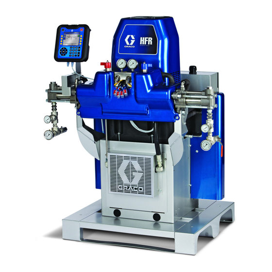
Hydraulic, Plural-Component, Fixed-Ratio Proportioner.
For pouring and dispensing sealants and adhesives and polyurethane foam.
For professional use only. Not for use in explosive atmospheres.
Important Safety Instructions
Read all warnings and instructions in this
manual. Save these instructions.
See page 4 for model information and maximum
working pressure.
313997ZAA
EN
ti19598a
Advertisement
Table of Contents
Troubleshooting

Related Manuals for Graco HFR


Summary of Contents for Graco HFR
- Page 1 Setup - Operation ™ 313997ZAA Hydraulic, Plural-Component, Fixed-Ratio Proportioner. For pouring and dispensing sealants and adhesives and polyurethane foam. For professional use only. Not for use in explosive atmospheres. Important Safety Instructions Read all warnings and instructions in this manual. Save these instructions. See page 4 for model information and maximum working pressure.
-
Page 2: Table Of Contents
Advanced Display Module (ADM) ... 30 Graco Information ......112 Fluid Control Module (FCM) . -
Page 3: Related Manuals
Related Manuals Related Manuals Manuals are available at www.graco.com. Accessory Manuals Component manuals in English: 3A1149 HFR Discrete Gateway Module Kits Manual System Manuals 312864 HFR Communications Gateway 313998 HFR Repair-Parts Module Instructions-Parts Power Distribution Box Manual 3A1657 HFR Flow Meter Kits... -
Page 4: Models
If 2000 psi hoses were purchased and installed by Graco, the working pressure for the machine is already setup for the lower 2000 psi (13.8 MPa, 138 bar) working pressure by Graco. If the machine was pur chased without hoses and aftermarket hoses rated at or above 3000 psi are to be installed, see instruction man ual 313998 for the procedure to setup the machine for higher rated hoses. -
Page 5: Product Configurator
An example of the product configurator would be the following configurator code. - A - 1 - 6 - AM - AM - D - AG Ref.: The following part number fields apply for the HFR part numbering configurator fields. Ref. 3 Part B (Blue) Pump †... - Page 6 Product Configurator 24E969 Single Hose, 1:1, 3/8 x 3/8, 10 ft, Carbon Steel, Ref. 5 Part Primary/Hose Heat 2000 psi No Heat 24D126 Single Hose, 1:1, 3/8 x 3/8, 25 ft, Carbon Steel, A (Red) and B (Blue) Primary Heaters 2000 psi A (Red) and B (Blue) Primary Heaters, One Zone 24D127 Single Hose, 1:1, 3/8 x 3/8, 50 ft, Carbon Steel,...
-
Page 7: Whip Hose Bundles
Product Configurator Whip Hose Bundles 24H225 5 ft (1.5 m) long, 1/4 in. (6 mm) ID, Carbon Steel, Single Zone, 3500 psi Part Description 24H227 5 ft (1.5 m) long, 3/8 in. (10 mm) ID, Carbon Steel, Single Zone, 3500 psi 24H076 10 ft (3 m) long, 1/4 in. -
Page 8: B (Blue) Individual
Product Configurator Hoses B (Blue) Individual Part Description Part Description 24E902 Heated Hose, 5 ft, 1/4, Carbon Steel, 3500 psi 24D111 Dual Hose, 2:1, 1/4 x 3/8, 50 ft, Stainless Steel, 24E904 Heated Hose, 10 ft, 1/4, Carbon Steel, 3500 psi 3500 psi 24E906 Heated Hose, 25 ft, 1/4, Carbon Steel, 3500 psi 24D115 Dual Hose, 1:1, 3/8 x 3/8, 50 ft, Stainless Steel,... -
Page 9: A (Red) Individual
Product Configurator 262239 Unheated Hose, 10 ft, 1/4, Stainless Steel, 262173 Unheated Hose, 5 ft, 1/4, Carbon Steel, 3500 psi 3500 psi 262175 Unheated Hose, 10 ft, 1/4, Carbon Steel, 262241 Unheated Hose, 25 ft, 1/4, Stainless Steel, 3500 psi 3500 psi 262177 Unheated Hose, 25 ft, 1/4, Carbon Steel,... -
Page 10: Applicator
24E897 Signal Cable, 5 pin, Male/Female, 16.0 meter the HFR, then the sizes of the A and B pumps added 24E896 Fluid Temperature Sensor Cable, 4 pin, together must be greater or equal to 120 cc. For exam Male/Female, 2.0 meter... -
Page 11: B (Blue) Applicator Orifice
Product Configurator B (Blue) Applicator Orifice 24D515 Applicator, MD2, 1:1, Hard, Stainless Steel, Lever 24D516 Applicator, MD2, 1:1, Hard, Stainless Steel, S-Head and L-Head Pneumatic Description Part For Use With Applicator: 24D521 Applicator, MD2, 10:1, Soft, Carbon Steel Calibrate 24A036 S-Head Only 24D522 Applicator, MD2, 10:1, Soft, Carbon Steel, Elec... - Page 12 Product Configurator 247868 L-Head Only 0.71 mm Poly 24C807 EP 250 Poly Side Orifice Orifice 247869 L-Head Only 0.89 mm Poly 24C808 EP 250 Poly Side Orifice 247870 L-Head Only Orifice 247871 L-Head Only 0.99 mm Poly 24C809 EP 250 Poly Side Orifice 247872 L-Head Only Orifice...
-
Page 13: Iso A (Red) Applicator Orifice
Product Configurator Iso A (Red) Applicator Orifice 0.71 mm Iso 24D231 EP 250 Iso Side Orifice Orifice 0.89 mm Iso 24D232 EP 250 Iso Side Orifice S-Head and L-Head Orifice 0.99 mm Iso 24D233 EP 250 Iso Side Orifice The A (Red) applicator orifices for the S-Head and Orifice L-Head are the same as the B (Blue) applicator orifices. -
Page 14: Ac Power Pack With S-Head/L-Head Hoses, Optional Boom
Product Configurator AC Power Pack with Flow Meters S-Head/L-Head Hoses, Optional Flow Meter Electronics (Necessary) Boom Part Description Part Description 24J318 Flow Meter Electronics Kit 24D829 230V, Boom, L-Head Hoses 24D830 230V, Boom, S-Head Hoses “A” and “B” Side Flow Meter (One for each side) 24D834 400V, Boom, L-Head Hoses Part Description... -
Page 15: Pump Feed Kits
Product Configurator Pump Feed Kits 24D102 Husky 1050 Pump with Stainless Steel Fluid Plumbing Part Description 24D103 2:1 Supply Pump with Stainless Steel Fluid Plumbing 246081 2:1 (Air/Fluid) Carbon Steel Complete Supply Pump Kit 24D104 5:1 Monarch Pump with Stainless Steel Fluid Plumbing 246369 H515 (Air/Fluid) Carbon Steel Complete Supply... -
Page 16: B (Blue) And A (Red) Feed Tanks
Product Configurator B (Blue) and A (Red) Feed Tanks 24J209 20gal (75L) Stainless Steel Tank, 3 Level Sen sors, Insulated Part Description 24J707 20gal (75L) Carbon Steel Tank, 3 Level Sensors, Insulated 24D562 38L Tank, No Agitation, Chiller, Desiccant, 2 Level Sensors 24J243 2gal (7.6L) Stainless Steel Tank... - Page 17 Miscellaneous Discrete Gateway Module (DGM) Part Description The HFR Discrete Gateway Module allows the user to control an HFR through multiple external control devices 24C871 Hydraulic Power Pack Hydraulic Tank Fluid Level Sensor such as contact blocks or relays. The DGM operates in...
-
Page 18: Warnings
Warnings Warnings The following warnings are for the setup, use, grounding, maintenance, and repair of this equipment. The exclama tion point symbol alerts you to a general warning and the hazard symbol refers to procedure-specific risk. Refer back to these warnings. Additional, product-specific warnings may be found throughout the body of this manual where applicable. - Page 19 Warnings WARNING FIRE AND EXPLOSION HAZARD Flammable fumes, such as solvent and paint fumes, in work area can ignite or explode. To help pre vent fire and explosion: • Use equipment only in well ventilated area. • Eliminate all ignition sources; such as pilot lights, cigarettes, portable electric lamps, and plastic drop cloths (potential static arc).
-
Page 20: Important Two-Component Material Information
Important Two-Component Material Information WARNING MOVING PARTS HAZARD Moving parts can pinch, cut or amputate fingers and other body parts. • Keep clear of moving parts. • Do not operate equipment with protective guards or covers removed. • Pressurized equipment can start without warning. Before checking, moving, or servicing equip ment, follow the Pressure Relief Procedure and disconnect all power sources. -
Page 21: Moisture Sensitivity Of Isocyanates
A (Red) and B (Blue) Components Moisture Sensitivity of • Never use solvent on one side if it has been con taminated from the other side. Isocyanates • Always lubricate threaded parts with ISO pump oil or grease when reassembling. Isocyanates (ISO) are catalysts used in two component foam and polyurea coatings. - Page 22 A (Red) and B (Blue) Components 313997ZAA...
-
Page 23: Typical Installation
A (Red) Side Supply Detail ti7821a3 ti7821a2 * Shown exposed for clarity. Wrap with tape during operation. ti14720a Key: HFR Unit (see F . 2, page 25) Feed Pumps Hose Agitator Fluid Temperature Sensor (FTS); 2x, 1 for each hose Desiccant Dryer... -
Page 24: Component Identification
FA Component A (Red) Fluid Manifold Inlet (on left side of manifold block) FB Component B (Blue) Fluid Manifold Inlet FM HFR Fluid Manifold FP Feed Inlet Pressure Gauge FS Feed Inlet Strainer (standard filter size is 20 mesh) FT Feed Inlet Temperature Gauge (heated models only) - Page 25 Component Identification 24C352_313998_3g Primary Heater (PH) Detail, Rear View Fluid Manifold (FM) Detail B (Blue) side shown ti9880a1 24C352_313998_4e 24C327_313998_1e . 2: Component Identification, Heated Model shown with shrouds removed 313997ZAA...
- Page 26 Component Identification Main Power Switch Additional circuit breakers for protection of the second ary side of the heated hose transformer are located Located on top of the power distribution box, see inside the frame. See the parts list for the installed pri page .
-
Page 27: Hydraulic Power Pack
Component Identification Hydraulic Power Pack 24C352_313998_2g Key: DA 8 Gallon Hydraulic Oil Reservoir (see Technical Data on DF Motor Control Module (see page 28) page 108 for specifications) DG Fan DB Electric Motor DH Oil Filter DC Dipstick (not shown, located at rear left of hydraulic tank) DJ Shroud (not shown, removed for clarity) DD Hydraulic Housing DK Air Inlet Filter... -
Page 28: Motor Control Module (Mcm)
(A) faces up. Motor Control Module or damage may occur. See HFR Repair manual for details, see Related Man The Motor Control Module uses an 8-position selector uals on page 3. - Page 29 Component Identification Description Access Cover LEDs Warning Label 1A, 1B CAN Connections Three-way Splitter to: Oil Low Level Sensor, Dispense Valve Solenoid, and Footswitch Oil Temperature Sensor Electric Motor Temperature Sensor LVDT Three-way Splitter to: Hydraulic Directional Valve, Oil Overtemperature Switch Pressure Transducer B (Blue) side Pressure Transducer A (Red) side Not used...
-
Page 30: Advanced Display Module (Adm)
Component Identification Advanced Display Module (ADM) User Interface TI12362a1 . 5: ADM Component Identification - Front Buttons Ref. Button Function Ref. Button Function Soft Defined by application using ADM. System Enables/disables system. When sys Keys enable/ tem is disabled, temperature control disable and dispense operation are disabled. - Page 31 Component Identification r_24E451_3B9900_1a . 6: ADM Component Identification - Rear Key: CJ Flat Panel Mount CN Module Status LEDs CK Model Number CP Accessory Cable Connections CL USB Module Interface CR Token Access Cover CM CAN Cable Connections CS Battery Access Cover System Status Indicator (CB) Conditions Green Solid - Run Mode, System On Green Flashing - Setup Mode, System On...
- Page 32 Component Identification Main Display Components The following figure calls out the navigational, status, and general informational components of each screen. For details regarding the user interface display see Advanced Display Module (ADM) Operation, page 46. Current date and time Previous screen Current screen Next screen Mode...
-
Page 33: Fluid Control Module (Fcm)
Component Identification Fluid Control Module (FCM) ti12337a1 ti12336a1 . 8: Key: Fluid Control Module Base Module Connection Screws Access Cover Module Status LEDs CAN Connectors 313997ZAA... -
Page 34: Temperature Control Module (Heated Hfr Only)
Component Identification Temperature Control Module (Heated HFR Only) Signals ti12352a1 ti12353a1 . 9: High Power Temperature Control Module Sensor Connections Key: Overtemperature Switch Connection (primary heaters DC Output Connection only) Input Power Connection RTD Temperature Sensor Connection CAN Connections Output Power Connection... - Page 35 Component Identification Heat Control Zone Selection (Heated models only) The HFR unit supports 4 independent temperature con trol zones. The high power temperature control modules are located inside the frame below the hydraulic power pack. Hose Heater B (Blue) Primary Heater B (Blue)
- Page 36 Component Identification Adjust Rotary Switch High Power Module Rotary Switch Settings Setting Zone The rotary switch setting indicates which zone the tem perature control module will control in the system. The Not Used high power module uses an 8-position rotary switch. B (Blue) Primary Heat The low power module uses a16-position rotary switch.
-
Page 37: Dispense Valves Overview
Dispense Valves Overview Dispense Valves Overview Three types of dispense valves can be used with the HFR system: • Stall-at-pressure • Solenoid controlled • Hydraulically actuated and recirculating The P2 Gun and Fusion Gun are examples of stall-at-pressure dispense valves. When not dispensing, the fluid in the chemical lines are fully pressurized. -
Page 38: Setup
Perform this setup procedure to secure all necessary Connect electrical cord. machine connections for machine operation. Locate HFR. a. Locate HFR on a level surface. See Dimen sions on page 110 for space requirements. NOTE: See Power Line Voltage Surges information on page 39. - Page 39 Setup Use 5/32 or 4 mm hex allen wrench to connect the two c. Press “Min Max” successively to show the peak or three power leads to L1, L2, and L3, as applicable. positive and negative DC voltages. Connect green to ground (GND). d.
- Page 40 (H). See . 1, page 23. NOTE: For Heated HFR models only, install Fluid Tem Supply hoses from feed pumps should be 3/4 in. perature Sensor (FTS) (19 mm) ID minimum. a. Install FTS between main hose and whip hose.
- Page 41 For Heated HFR Models only, connect Connect heated hose monitor zones cables (Y). Connect electrical connectors (V). NOTE: For Heated HFR models only, see Heated Hose Be sure cables have slack when hose bends. manual for detailed instructions on connecting heated Wrap cable and electrical connections with hoses.
- Page 42 Ground system This equipment must be grounded. 24C352_312998_8g a. HFR: grounded through power cord. See step 3 b. Fill with fresh fluid. Thread the reservoir onto on page 38. the cap assembly and place it in the b. EP Gun or Dispense Valve: If supplied, connect bracket (RB).
- Page 43 Setup 14. Prime IsoGuard Select fluid cylinder g. Press to enable system. LED should be solid green. The IsoGuard Select fluid cylinder must be primed when ® replacing IsoGuard Select fluid. See IsoGuard Select h. Check that heat zones are on and temperatures System on page 57 for instructions.
-
Page 44: Vacuum De-Gas
2. Close the shut-off ball valves at the base of the tanks. p. For Fusion dispense valves, perform DC Power Pack Hydraulic Pressure Setup. See HFR 3. If the tank lid has a fill port, turn off any systems that might refill the tank during the vacuum de-gas pro Repair manual for procedure. -
Page 45: Vacuum De-Gas And Vacuum Manual Refill
Setup Vacuum De-gas and Vacuum 12. Close bottom ball valve of the vacuum tree mani fold). Manual Refill 13. Turn off the vacuum pump. NOTE: This procedure is for assemblies with a vacuum tree manifold, agitator, and auto-refill. 14. Open the top ball valve of the vacuum tree manifold. NOTICE 1. -
Page 46: Advanced Display Module (Adm) Operation
Advanced Display Module (ADM) Operation Advanced Display Module (ADM) Operation When main power is turned on by turning the main 7. If L-Head is installed, define L-Head control power switch (MP) to the ON position, the splash screen details. See Mix Head Operating Details Screen, will be displayed until communication and initialization is page 74. -
Page 47: Startup
Use feed pumps to load fluid ti10002a1 NOTE: The HFR is tested with oil at the factory. Flush out the oil with a compatible solvent before dispensing. See Flush ing on page 52. Keep Components A (Red) and B (Blue) Separate a. - Page 48 Calibrate HFR mechanical limits of travel. If the pump did not reach The HFR calibration procedure is a two step process. both the left and right extreme limits for any reason, The first step, Learn Mode, must be performed when repeat the procedure.
- Page 49 Startup Set temperatures (Heated models only) Change pressure imbalance setting (optional) The pressure imbalance function detects conditions that can cause off-ratio dispense, such as loss of feed pres sure/supply, pump seal failure, clogged fluid inlet filter, This equipment is used with heated fluid, which can or a fluid leak.
-
Page 50: Shutdown
Shutdown Shutdown 1. Park pumps. a. From the Home screen, press and select Standby mode. b. Press . Material will dispense for non cir culation systems. Pump will park automatically. Once pump is parked, pump will stop moving. If a dispense gun with a trigger is installed, pulling the trigger will begin a park operation. -
Page 51: Pressure Relief Procedure
Pressure Relief Procedure Pressure Relief Procedure 1. Shut off feed pumps and agitator, if used. 2. Turn PRESSURE RELIEF/DISPENSE valves (SA, SB) to PRESSURE RELIEF/CIRCULATION Route fluid to waste containers or supply tanks. Ensure gauges drop to 0. ti9879a1 3. For models with an dispense valve with a safety lock, engage gun safety lock. -
Page 52: Flushing
Flushing Flushing • To maintain grounding continuity when flushing or relieving pressure, hold a metal part of dispense gun firmly to the side of a grounded metal pail, then trigger gun. Flush equipment only in a well-ventilated area. Do not dispense flammable fluids. -
Page 53: Maintenance
Maintenance Maintenance Change Break-in Oil After initial break-in, see Table 5 for recommended fre quency of oil changes. Table 2: Frequency of Oil Changes Task Schedule Ambient Recommended Change break-in oil in a new unit After first 250 Temperature Frequency hours of opera tion or within 3 0 to 90°F... -
Page 54: Adm - Battery Replacement And Screen Cleaning
Maintenance ADM - Battery Replacement and MCM and TCM - Clean Heat Sink Screen Cleaning Fins Battery Replacement Keep heat sink fins clean at all times. Clean them using compressed air. A lithium battery maintains the ADM clock when power is not connected. -
Page 55: Install Upgrade Tokens
To install software upgrades: 1. Use correct software token stated in the table. See ™ r_257396_3b9905_04b Graco Control Architecture Module Programming manual for instructions. ti12334a1 NOTE: Upgrade all modules in the system to the software version on the token, even if you are replacing only one or two modules. -
Page 56: Fluid Inlet Strainer Screen
Maintenance Fluid Inlet Strainer Screen 6. Open the fluid inlet valve, ensure that there are no leaks, and wipe the equipment clean. Proceed with operation. The inlet strainers filter out particles that can plug the 59g* pump inlet check valves. Inspect the screens daily as part of the startup routine, and clean as required. -
Page 57: Isoguard Select ® System
Maintenance ® 9. Push the return tube (RT) into the reservoir until it IsoGuard Select System reaches the bottom. NOTE: The return tube must reach the bottom of the reservoir, to ensure that isocyanate crystals will settle to the bot Check the condition of the A (Red) pump IsoGuard tom and not be siphoned into the supply tube and Select fluid daily. -
Page 58: Troubleshooting
Troubleshooting Troubleshooting Light Tower (Optional) Signal Description Green on only System is powered up and there are Before performing any troubleshooting procedure: no error conditions present Yellow on An advisory exists 1. Perform Pressure Relief Procedure on page 51. Red flashing A deviation exists 2. - Page 59 Troubleshooting Problem Cause Solution Hose Heat System Hose heats but heats slower Ambient temperature is too cold Use auxiliary hose system. than usual or it does not FTS failed or not installed correctly Check FTS reach temperature Low supply voltage Verify line voltage.
- Page 60 Troubleshooting Problem Cause Solution Material imbalance. Inadequate flow from pump; cavitation Increase fluid supply to proportioning pump: • Use 2:1 supply pump • Use minimum 3/4 in. (19 mm) ID supply hose, as short as practical Fluid is too thick. Consult your material supplier for the recommended fluid temperature to maintain a vis cosity of 250 to 1500 centipoise.
-
Page 61: Adm Troubleshooting
Troubleshooting ADM Troubleshooting r_24E451_3B9900_1a . 18: ADM Component Identification - Rear ADM Module Status LEDs (CN) Conditions Module Status LED Signal Description Green on System is powered up. Yellow on Communication in progress. Red solid ADM hardware failure. Red flashing Uploading software. -
Page 62: Motor Control Module
Troubleshooting Motor Control Module For MCM location, see reference MA in F . 2 on page 25. Diagnostic Information Table 3: LED Status Signal Module Status LED Signal Description Green on System is powered up. Yellow on Internal communication in progress. Red solid MCM hardware failure. - Page 63 Troubleshooting Acceptable Size and Duration of Power Line Voltage Fluctuations The Motor Control Module is designed to withstand volt age fluctuations from the incoming power supply. If the incoming power supply goes outside of the tolerable range, an over-voltage condition is flagged and the sys tem shuts down in an alarm state.
-
Page 64: Fluid Control Module
Troubleshooting Fluid Control Module Diagnostic Information Module Status LED Signal Diagnosis Green on System is powered up Yellow Internal communication in progress Red solid FCM hardware failure. Replace FCM. Red flashing fast Uploading software Red flashing slow Token error. Remove token and upload software token again. -
Page 65: Temperature Control Module
Troubleshooting Temperature Control Module Diagnostic Information Module Status LEDs Signal Description Green on Temperature control module is powered up. Yellow on Internal communication in prog ress. Red solid Temperature control module fail ure. See Troubleshooting table. Red flashing Software is updating. Blue light off Temperature control module is off. -
Page 66: Appendix A - Adm Icons Overview
Appendix A - ADM Icons Overview Appendix A - ADM Icons Overview Setup Screen Icons Icon Description Icon Description Erase All Counters on Page Enter Screen Access Flowmeter Calibration Exit Screen On Learn Mode Calibration screen: Valve Details Move pump Selects all shots to be changed to the All other screens: same user specific value... -
Page 67: Run Screen Icons
Appendix A - ADM Icons Overview Run Screen Icons Icon Description Icon Description Sets machine to low pressure Select mode. Set system in park (icon will be Sets machine to high pressure selected when system is parked) Current and setpoint temperature for Open, Close Valve primary heater. -
Page 68: Appendix B - Adm Setup Screens Overview
Appendix B - ADM Setup Screens Overview Appendix B - ADM Setup Screens Overview The ADM will start in the Run screens at the “Home” From the Setup screens, press to access the Run screen. From the Run screens, press to access screens. - Page 69 Appendix B - ADM Setup Screens Overview ∆ Shots Screen column Due to variation in material properties, the gives the ability to adjust the shot time/volume/weight This screen allows the user to edit shot definitions. The for each defined shot. contents of this screen change based on the Dispense and Control Mode selections.
- Page 70 Appendix B - ADM Setup Screens Overview ∆ Volume/Weight Based Example: 4. Use the following formula to calculate the column value. A 75 cc/s shot is defined to dispense for 75 cc. ((Flow Rate x Time) - Average Volume) Flow Rate Example 1: ((75cc/sec x 2sec) - 146cc) = 0.053 sec...
- Page 71 Appendix B - ADM Setup Screens Overview ∆ Sequences Screen 5. Enter the calculated value in the column. This screen allows the user to edit sequence informa Example 3: tion. The contents of this screen change based on the Dispense and Control Mode selections. Dispense detail is shown as volume, time, or weight depending on which Dispense Mode is selected.
- Page 72 See The piston can be moved to the left and right to obtain Calibrate HFR on page 48 for how to use the calibration the full range of motion. See Calibrate HFR on page 48 screens to calibrate the machine.
- Page 73 If the sensors are not is dispensed. See Calibrate HFR on page 48 for more marked as enabled, they will be ignored by the machine information.
- Page 74 • Low Pressure Circulation: The percentage of set before the HFR will start a dispense. This feature is not point at which the system will run during low pres available for recirculation systems or applicable for sure circulation.
- Page 75 The ratio Refer to the HFR Flow Meter Kits manual for instruc alarm value is the allowable percentage difference tions on how to calibrate the flow meters.
- Page 76 Appendix B - ADM Setup Screens Overview Maintenance Screen Supply Screen This screen shows shot number, sequence position, and This screen allows the user to specify the operating parameters for off-board, integrated tanks and indicate which positions have level sensors installed. See the dispense valve counters.
- Page 77 Appendix B - ADM Setup Screens Overview • When the high level sensor does not see mate Refill Sensor Type rial, automatic refill will begin and continue until The Low-Temp Sensor setting limits tank temperatures either the high level sensor sees material or to 150°F (66°C).
- Page 78 Appendix B - ADM Setup Screens Overview Conditioning Screen 2 This screen shows the fluid path for the temperature 2. Press to display the setpoint and alarm values conditioning components and temperature setpoints for associated with that component. each component. NOTE: If tank blanket heaters or inline heaters are installed along with hose heat, the hose heat setting will be limited to at or below the inline or tank heat setting.
- Page 79 Appendix B - ADM Setup Screens Overview Conditioning Screen 3 Time Based Night Mode Conditioning Screen This screen allows the user to set a specific time each This screen allows the user to configure Night Mode day to turn the machine on or off. The times can be set operation.
- Page 80 Appendix B - ADM Setup Screens Overview NOTE: If times are entered in the weekly schedule, indi Advanced Screen 1 vidual days can not be erased. This screen allows the user to set the language, date format, current date, time, setup screens password, Cold Start Up Mode screen saver delay, and turn on or off silent mode.
- Page 81 This screen allows the user to control the availability of • Limit Rate on Stall to Pressure: Check this box to some key system features. allow the HFR to increase to stalling pressure at a slower, more controlled rate. • Disable Dispensing From Display: Check this box to disable dispensing from the ADM.
-
Page 82: Appendix C - Adm Run Screens Overview
Appendix C - ADM Run Screens Overview Appendix C - ADM Run Screens Overview Run screens are divided into five major sections: status, errors, events, and maintenance. The following diagram demonstrates the flow of the Run screens beginning with the Home screen. Home Status Errors #1... - Page 83 Appendix C - ADM Run Screens Overview Home Screen, Standby Mode Home Screen, Shot Mode In Standby Mode, the user can enable heating, park the This mode allows the user to select one of 100 pre pumps, refill the tanks, circulate materials. defined shot numbers.
- Page 84 Appendix C - ADM Run Screens Overview Home Screen, Sequence Mode Home Screen, Operator Mode This mode allows the user to select one of five This mode allows users to set a pressure or flow rate to sequences (A-E). The progress bar on the bottom of the dispense material without using predefined shot infor screen shows the progress of a shot dispensing from mation.
- Page 85 Appendix C - ADM Run Screens Overview Home Screen, Night Mode Status Screen The status screen provides all of the operational func In Night Mode, the system will cycle on and off tionality of the Home screen except for operating mode periodically.
- Page 86 Appendix C - ADM Run Screens Overview Status Screen, Conditioning Control Errors Screens This screen allows users to turn on and off heat zones This screen shows users a list of errors that have individually or all at once. When a zone is on it is occurred in the system.
- Page 87 Appendix C - ADM Run Screens Overview Maintenance Screen 1 Optional Screens This screen displays historical information for each The optional Diagnostic screen can be enabled in the pump in the system. The Batch counters are resettable Advanced Screen 4 screen, see page 81. and count both material usage and pump cycles.
-
Page 88: Appendix D - Adm Error Codes
Appendix D - ADM Error Codes Appendix D - ADM Error Codes Error Error Code Error Name Error Description Type Cause Solution Mix Head A4H3 Motor Overload Soft Stop DEH3 Asserted Low Mix MBH3 Head Oil Level P1H3 Accumulator Pressure Refer to AC Power Pack manual High P4H3... - Page 89 Alarm Current commanding too much current Module code software, if problem persists contact Graco On the ADM go into the Setup screens to the System The requested dispense Pumps are defined with screens then make sure that the pump sizes are...
- Page 90 Appendix D - ADM Error Codes Error Error Code Error Name Error Description Type Cause Solution Comm. Error CAA2 Module missing power Check power supply connection Red Hose Comm. Error CAA3 Module not programmed Program the module Red Inline Comm. Error CAA6 Red Blanket Comm.
- Page 91 Appendix D - ADM Error Codes Error Error Code Error Name Error Description Type Cause Solution This calibration lets the MCM Recalibrate the machine Rerun the learn mode calibration know where the ends of the Check to ensure the pressure transducer is properly Loose/bad connection pump are.
- Page 92 Appendix D - ADM Error Codes Error Error Code Error Name Error Description Type Cause Solution Red Tank L8A1 Sensor Failure A level sensor had ceased Deviation Bad level sensor Replace level sensor Blue Tank working DR6B Sensor Failure Low oil level Check oil level and if low add more hydraulic fluid Check to ensure the hydraulic oil level sensor is Loose/bad connection...
- Page 93 Appendix D - ADM Error Codes Error Error Code Error Name Error Description Type Cause Solution Red Pressure Dispense valve failed to Check to make sure the dispense valve is properly P4A1 Shutdown open configured and connected to the MCM Bad dispense valve Replace dispense valve Restriction in the...
- Page 94 Appendix D - ADM Error Codes Error Error Code Error Name Error Description Type Cause Solution Red Tank T1A6 Low Fluid Temp. Blue Tank T1B5 Low Fluid Temp. Red Inline T1A3 Low Fluid Tripped circuit breaker Visually check circuit breaker for a tripped condition Temp.
- Page 95 Appendix D - ADM Error Codes Error Error Code Error Name Error Description Type Cause Solution Red Hose T2AA Low Fluid Temp. Red Tank T2AE Low Fluid Temp. Temperature is out of Check temperature alarm limits alarm limits Red Chiller T2AF Low Fluid Fluid temperature for a monitor...
- Page 96 Appendix D - ADM Error Codes Error Error Code Error Name Error Description Type Cause Solution Red Hose T4A2 High Fluid Temp. Red Inline T4A3 High Fluid Temp. Red Tank T4A6 High Fluid Temp. Defective Temperature Replace Power Temperature Control Module Control Module Red Chiller T4A7...
- Page 97 Appendix D - ADM Error Codes Error Error Code Error Name Error Description Type Cause Solution Red Blanket T6C6 RTD Fault Blue Blanket T6C5 Loose or bad connection Check RTD wiring RTD Fault RTD 2 is giving no or invalid Alarm data Red Chiller...
- Page 98 Appendix D - ADM Error Codes Error Error Code Error Name Error Description Type Cause Solution Tripped circuit breaker Visually check circuit breaker for a tripped condition The voltage to the MCM has Motor Control V1H1 dropped to a level where Alarm Supply lines providing Check incoming voltage to ensure it is above the...
- Page 99 Appendix D - ADM Error Codes Error Error Code Error Name Error Description Type Cause Solution Red Tank WM06 Con. Fault Blue Tank WM05 Con. Fault Red Inline WM03 Con. Fault Blue Inline WM01 Con. Fault High current to relay 1 Alarm Broken contactor Replace contactor...
-
Page 100: Appendix E - System Events
Appendix E - System Events Appendix E - System Events Event Code and Event Code and String Triggers String Triggers REQU2: Settings The system settings file was success REL00: System Pow The System was powered on. Uploaded fully transferred from the USB drive to ered On the ADM. - Page 101 Appendix E - System Events 313997ZAA...
-
Page 102: Appendix F - Usb Operation
Appendix F - USB Operation Appendix F - USB Operation Overview Download Log Files ™ If the “Enable Downloading of USB Logs” is checked, There are 3 main uses for the USB on a GMS system the user can use a USB stick-drive to download the log files. -
Page 103: Log Files, Folder Structure
Appendix F - USB Operation Log Files, Folder Structure . 24: DOWNLOAD, DATAxxxx Folders Each time a stick-drive is inserted into the ADM USB port, a new folder named DATAxxxx is created. The number at the end of the folder name is incremented each time a stick-drive is inserted and data is downloaded or uploaded. In each DATAxxxx folder there is three log files. - Page 104 Appendix F - USB Operation Example 2-JOB File The 2-JOB file is the Shot Data Log file. Example 3-SYSTEM File The 3-SYSTEM file is the Software Version log file. 313997ZAA...
-
Page 105: Transfer System Settings
The user should never attempt to modify the SET remove the SETTINGS.TXT file from the UPLOAD TINGS.TXT file in any way. Graco is not responsi folder to prevent accidental loss of data the next time ble for damages caused by an improperly modified the USB stick-drive is inserted into the ADM USB port. -
Page 106: Update Custom Language
Appendix F - USB Operation Update Custom Language 8. When the software is done updating, remove the NOTICE USB stick-drive from the ADM USB port and install Low-quality USB stick drives may lead to burning in a computer. out the USB port on the ADM. Use only high-quality USB stick-drives with the ADM USB port. - Page 107 Appendix F - USB Operation Example SETTINGS.TXT File Example DISPTEXT.TXT File NOTICE The user should never attempt to modify the SET TINGS.TXT file in any way. Graco is not responsi ble for damages caused by an improperly modified setup file. 313997ZAA...
-
Page 108: Technical Data
Heater Power (A (Red) and B (Blue) heaters total, no hose, Heated HFR Models only). . 12 kW Hydraulic reservoir capacity..9 gal. (34 liters) Recommended hydraulic fluid ..Citgo A/W Hydraulic Oil, ISO Grade 46 Weight . -
Page 109: Motor Control Module Technical Data
DC Power Supply ....... 24 Vdc, Class 2, Graco-provided power supply Enclosure . -
Page 110: Dimensions
Motor Control Module Technical Data Dimensions 34.1 in. 47.5 in. (870 mm) (1210 mm) 59.8 in. (1520 mm) Bolt Mounting Pattern and Dimensions Type of Base No Pallet Pallet Right 24 in. 32.4 in. (610 mm) (823 mm) 15 in. 30.3 in. - Page 111 Motor Control Module Technical Data 313997ZAA...
-
Page 112: Graco Standard Warranty
With the exception of any special, extended, or limited warranty published by Graco, Graco will, for a period of twelve months from the date of sale, repair or replace any part of the equipment determined by Graco to be defective.
Need help?
Do you have a question about the HFR and is the answer not in the manual?
Questions and answers