Table of Contents
Advertisement
Quick Links
Operation
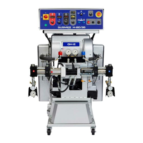
H-20/35 Pro
Proportioner
For spraying polyurethane foam and polyurea coatings.
Not for use in explosive atmospheres.
Important Safety Instructions
Read all warnings and instructions in this manual.
Save these instructions.
See page 3 for model information, including
maximum working pressure.
Graco Inc. P.O. Box 1441 Minneapolis, MN 55440-1441
Copyright 2006, Graco Inc. is registered to I.S. EN ISO 9001
™
311392 rev.C
Advertisement
Table of Contents

Related Manuals for Graco Gusmer H-20 Pro


Summary of Contents for Graco Gusmer H-20 Pro
- Page 1 Read all warnings and instructions in this manual. Save these instructions. See page 3 for model information, including maximum working pressure. Graco Inc. P.O. Box 1441 Minneapolis, MN 55440-1441 Copyright 2006, Graco Inc. is registered to I.S. EN ISO 9001...
-
Page 2: Table Of Contents
Graco Standard Warranty ....24 Graco Information ......24 Related Manuals For Repair instructions and parts, see manual 311393. -
Page 3: Models
Models Models Maximum Working Total Part No., Pressure Heater Series Model psi (MPa, bar) Voltage Amps Watts 295500, A H20 Pro 2000 (13.8, 138) 230V, 60 Hz, 1 phase 12000 295501, A H20 Pro 2000 (13.8, 138) 230V, 60 Hz, 3 phase 12000 295502, A H20 Pro... -
Page 4: Warnings
Warnings Warnings The following general warnings are for the setup, use, grounding, maintenance, and repair of this equipment. Addi- tional, more specific warnings may be found throughout the body of this manual where applicable. Symbols appear- ing in the body of the manual refer to these general warnings. When these symbols appear throughout the manual, refer back to these pages for a description of the specific hazard. - Page 5 Read fluid and solvent manufacturer’s warnings. For complete information about your material, request MSDS forms from distributor or retailer. • Check equipment daily. Repair or replace worn or damaged parts immediately with genuine Graco (ASM) replacement parts only. •...
-
Page 6: Pressure Relief Procedure
Pressure Relief Procedure Pressure Relief Flushing Procedure 1. Select Park on Pump Control Switch. 2. Turn off feed pumps. Flush equipment only in a well-ventilated area. Do not spray flammable fluids. Do not turn on heaters while 3. Trigger gun to relieve pressure. flushing with flammable solvents. -
Page 7: Typical Installation
Typical Installation Typical Installation . 1: H-20/35 Proportioner Typical Installation 311392C... -
Page 8: Component Identification
Component Identification Component Identification . 2: Component Identification - Main Components 311392C... - Page 9 Component Identification Hydraulic Pressure Control A- (Isocyanate) Inlet Supply Ball Valve Pressure control knob is factory-set (full clockwise) Allows delivery of isocyanate to proportioning unit. to maximum rated hydraulic pressure. To decrease hydraulic pressure, turn knob counterclockwise 10 Hydraulic Pressure Gauge (knob will stop after approximately 2 turns).
- Page 10 Component Identification . 4: Component Identification - Front Controls 20 Main Power Disconnect 22 Control Power Switch Controls power to all circuits. Must be ON for any Controls120 VAC control power circuit. In ON function of proportioning unit to operate. Lock position, amber light within switch illuminates.
- Page 11 Component Identification 26 Pump Switch Digital display of controller is energized when Controls operation of proportioning pump hydraulic control power switch is activated. B- primary heater drive cylinder. Pump switch has 3 settings: switch must be in ON position before heating process begins.
- Page 12 Component Identification Front of Machine . 6: Electrical Console Components 38 Control Main Terminal Block 44 A- (Isocyanate) Primary Heater Contractor Termination/distribution point for control system Supplies line voltage to A-primary heater. A- component wires. primary heater switch controls contractor. 39 Control Transformer Secondary Circuit Breaker 45 B- (Resin) Primary Heater Control Contractor Provides over-current protection for control...
- Page 13 Component Identification 50 Hose Heat Transformer Primary Circuit Breaker Provides over-current protection for hose heat transformer primary circuit. 51 Control Transformer Primary Circuit Breaker Provides over-current protection for control transformer primary circuit. 52 Power Distribution Block Provides power distribution point for incoming line voltage to circuit breaker bank.
-
Page 14: Initial Set-Up
Initial Set-up Initial Set-up Main Power Installation b. Connect ground wire to Ground Lug located inside console near strain relief opening. Installing this equipment requires access to parts that may cause electric shock or other serious injury if work is not performed properly. Have a qualified electrician connect power and ground to main power switch termi- nals. -
Page 15: Lubrication System Set-Up
Initial Set-up Add fluid as required and reattach fitting and b. The 2:1 Transfer Pump has a ground lug. hose. Ground pump in accordance with the 2:1 Trans- fer Pump manual. 4. Single-Phase Units: proceed to Step 5. Three-Phase Units only: Ensure electrical motor is c. -
Page 16: Material Supply Connections
Initial Set-up Material Supply Connections Heated Hose Installation Connect material supply to inlets of proportioning unit as follows: Hose connection points are a potential source of Main air supply must be clean and free of contami- chemical and air leaks. These areas are also most nants. - Page 17 Initial Set-up 2. Connect heated hose assembly to isolation hoses: a. Lay out hose assemblies end-to-end as shown in F . 12. A- (isocyanate) hoses are RED. B- (resin) hoses are BLUE. . 14: Hose Connection (step d) e. Connect FTS harness plugs. To ensure a secure electrical connection, place protective isolator boot over each plug and tape together.
- Page 18 Initial Set-up 4. Install Fluid Temperature Sensing unit (FTS) to gun e. Connect FTS harness to FTS. To ensure a whip hose as follows: secure electrical connection, place protective electrical isolator boot over each plug and tape a. Pull out and carefully straighten loose end of together.
-
Page 19: Air Purge
Initial Set-up Air Purge 9. Allow material to flow out of coupling block until spit- ting of air stops and all traces of residual material have disappeared. Close manual valves and flush any residual chemical from outside of coupling block. See Gun Operation Manual. Properly dispose of waste chemicals in accordance Prior to using equipment, purge chemical system of air with applicable local, state, and federal codes. -
Page 20: Digital Temperature Controllers
Initial Set-up Digital Temperature Controllers 5. After set point is entered, press and release buttons together to display actual The proportioner has three temperature controllers that temperature. automatically manage the temperature for the primary heaters and the hose heater. To prevent damage to primary heaters and hoses, Controllers are factory programmed and are not field do not turn on heat controller switches under tem- programmable. -
Page 21: Operation
Operation Operation Daily Start-up Procedure set point. If you need to change either set point, see Digital Temperature Controllers, page 20. Primary heating ramps up at 10°F (5.5°C) per minute. Do not turn on primary heaters until required for operation. Turn off primary heaters dur- ing shutdowns that exceed 30 minutes. -
Page 22: Daily Shutdown Procedure
Operation Daily Shutdown Procedure 5. Turn OFF green hose heater switch; light will turn off. 1. Set pump switch to RETRACT. 6. Turn OFF amber control power; light will turn off and temperature controller will go out. 2. Trigger spray gun off target until isocyanate pump stops in retracted position and spray pattern begins 7. -
Page 23: Technical Data
Technical Data Technical Data Category Data Maximum working pressure Model H20 Pro: 2000 psi (13.8 MPa, 138 bar) Model H25 Pro: 2500 psi (17.2 MPa, 172 bar) Model H35 Pro 104: 2800 psi (19.3 MPa, 193 bar) Model H35 Pro: 3500 psi (24.0 MPa, 240 bar) Maximum fluid temperature 190°F (88°C) Maximum output... -
Page 24: Graco Standard Warranty
With the exception of any special, extended, or limited warranty published by Graco, Graco will, for a period of twelve months from the date of sale, repair or replace any part of the equipment determined by Graco to be defective.
Need help?
Do you have a question about the Gusmer H-20 Pro and is the answer not in the manual?
Questions and answers