GE MAC 1600 Service Manual
Ecg analysis system
Hide thumbs
Also See for MAC 1600:
- Manual (9 pages) ,
- Service manual (54 pages) ,
- Operator's manual (162 pages)

Subscribe to Our Youtube Channel
Related Manuals for GE MAC 1600


Summary of Contents for GE MAC 1600
- Page 1 GE Healthcare MAC™ 1600 ECG Analysis System — Product Code SDE Service Manual Software Version 1.0.4 2028451-183 Revision E MAC™ 1600 ECG Analysis System English © 2008-2012 General Electric Company. All Rights Reserved.
- Page 2 Marquette, Archivist, CardioSoft, CASE, Hookup Advisor, MAC, MARS, Mactrode, Multi-Link, MUSE, SilverTRACE, 12SL and BabyMAC are trademarks owned by GE Medical Systems Information Technologies, Inc., a General Electric Company going to market as GE Healthcare. All other trademarks contained herein are the property of their respective owners.
-
Page 3: Table Of Contents
Contents Introduction Intended User....................7 Indications for Use ..................7 Contraindications ..................7 Prescription Device Statement ..............7 Regulatory and Safety Information............. 8 Safety Conventions ................. . . 8 Safety Hazards. - Page 4 Block Diagram................... 26 Hardware/Firmware Architecture............. 27 Troubleshooting General Fault Isolation................29 Power Up Self-Test ................. . . 29 Poor Quality ECGs .
- Page 5 MAC 1600 Upper Level Assembly, PN 2032093 ........
- Page 6 Value Accessories ................... 142 Thermal Papers ..................142 Country-Specific Power Cords..............143 Optional Accessories................143 MAC™ 1600 2028451-183E...
-
Page 7: Introduction
This device is intended for use under the direct supervision of a licensed health care practitioner. Contraindications The MAC 1600 device is NOT intended: • to be used during patient transport, • to be used for intra-cardiac applications, • to be used as a vital signs physiological monitor, or •... -
Page 8: Regulatory And Safety Information
Introduction Regulatory and Safety Information This section provides information about the safe use and regulatory compliance of this device. Familiarize yourself with this information and read and understand all instructions before attempting to use this device. The system software is considered medical software. -
Page 9: Parts And Accessories Information
60601-1 and/or 60601-1-1 standard(s). Responsibility of the Manufacturer GE Healthcare is responsible for the effects of safety, reliability, and performance on GE-supplied hardware only if the following conditions are met: • Assembly operations, extensions, readjustments, modifications, or repairs are carried out by persons authorized by GE Healthcare. -
Page 10: Symbols
Introduction Symbols The following symbols may appear on the device or its packaging. Familiarity with these symbols assists in the safe use and disposal of the equipment. For equipment symbols not shown, refer to the original equipment manufacturers (OEM) manuals. Defibrillation-proof type BF equipment. - Page 11 Introduction This way up. Recyclable. Atmospheric limits. Temperature limits. Humidity limits. Keep dry. Fragile. Do not throw or dispose of in fire. 2028451-183E MAC™ 1600...
- Page 12 Introduction Indicates the device is classified as type 20 for solid and liquid ingress per IEC/EN 60529. • X = Ingress of solid objects: • 0 non-protected • 1 >= 50 mm dia • 2 >=12.5 mm dia • 3 >=2.5 mm dia •...
-
Page 13: Training
GE Healthcare Education Store at www.gehealthcare.com/educationstore. Equipment Identification Every GE Healthcare device has a product label that identifies the product name, part number, manufacturing information, and unique serial number. This information is required when contacting GE Healthcare for support. -
Page 14: Serial Number Format
Fiscal Week Two-digit code identifying the week the device Manufactured was manufactured. Values range from 01 to 52. GE Healthcare's fiscal weeks correspond to the calendar week. For example, 01 = first week in January. Product Sequence Four-digit number identifying the order in which this device was manufactured. -
Page 15: Service Information
Additional Assistance GE Healthcare maintains a trained staff of application and technical experts to answer questions and respond to issues and problems that may arise during the installation, maintenance, and use of this product. - Page 16 Introduction Typographical Conventions Convention Description Bold Text Indicates keys on the keyboard, text to enter, or hardware items such as buttons or switches on the equipment. Italicized-Bold Indicates software terms that identify menu items, buttons or options in Text various windows. CTRL+ESC Indicates a keyboard operation.
-
Page 17: Related Documents
Introduction Related Documents You can find additional information in the following documents: Documents Related to this manual Part Number Document Title 2028451-182 MAC™ 1600 ECG Analysis System Operator’s Manual 2028451-183E MAC™ 1600... - Page 18 Introduction MAC™ 1600 2028451-183E...
-
Page 19: Equipment Overview
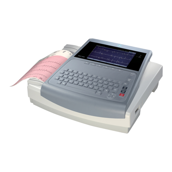
Equipment Overview The MAC™ ECG Analysis System is a 12–lead, 12–channel system with a 6.5 inch (165 mm) diagonal display, active patient cable, and battery operation. There are also options for communication capabilities. Front View Front View of the System Item Name Description... -
Page 20: Side View
Equipment Overview Front View of the System (cont'd.) Item Name Description Battery LED Indicates various battery states: • Solid amber light indicates the battery is charging. • Flashing amber light indicates the battery is low. • No light indicates the battery is neither charging nor low. -
Page 21: Rear View
Equipment Overview Rear View Rear View of the System Item Name Description External power connector 12V power supply for future external devices. Do not use. COMM Port A Serial connector for stress devices (bicycle ergometer or treadmill). COMM Port B Serial connector for data communication with a CASE/CardioSoft or MUSE system, or connection to an external modem. -
Page 22: Keyboard
Equipment Overview Rear View of the System (cont'd.) Item Name Description External Video Monitor Standard 15-pin VGA connector for an external connection monitor. Connect a medical grade VGA CRT or medical grade VGA compatible LCD display. NOTE: The display resolution is 800 by 480 pixels. - Page 23 Equipment Overview Standard Keyboard Item Name Description function keys (F1 through F6) Use to select menu options on the screen. Power switch Use to turn the system on, bring the system to Standby mode, or turn the system off. Leads key Use to change the leads when the screen is displaying waveforms.
-
Page 24: Keyboard (Stress Option)
Equipment Overview Keyboard (Stress Option) NOTE: The English keyboard is shown in this section. Item Name Description Pretest key Press to advance to the PRETEST phase (or advance to next stage within the selected phase). Exercise key Press to advance to the EXERCISE phase (or advance to next stage within the selected phase). - Page 25 Equipment Overview Item Name Description Medians key Press to print a medians report. 12ld key Press to print a 12–lead report (10 seconds of acquired data). Recall key Press to print a one-page rhythm strip using the previous 10 seconds of data. 2028451-183E MAC™...
-
Page 26: Block Diagram
Equipment Overview Block Diagram MAC™ 1600 2028451-183E... -
Page 27: Hardware/Firmware Architecture
Equipment Overview Hardware/Firmware Architecture The hardware subsystems include the following: • CPU core • Display • Keyboard • ECG Acquisition • Thermal printer • Power supply • Housing 2028451-183E MAC™ 1600... - Page 28 Equipment Overview MAC™ 1600 2028451-183E...
-
Page 29: Troubleshooting
Troubleshooting General Fault Isolation Refer to your system’s Operator’s Manual, Chapter 2, “Equipment Overview” to verify operation of the device. Power Up Self-Test On power-up, the system automatically runs an internal self-test. If all tests pass, you see the following start-up screen. The next screen to open depends on the Power Up mode selected in System Configuration. -
Page 30: Poor Quality Ecgs
Troubleshooting • Is the battery installed? • When connected to the AC wall outlet, does the green AC power light glow? Poor Quality ECGs Several factors can cause poor ECGs, including: • Factors in the environment. • Inadequate patient preparation. •... -
Page 31: Event Logging
Troubleshooting Visual Inspection Checklist (cont'd.) Area Look for the following problems Fasteners Loose or missing screws or other hardware, especially fasteners used as connections to ground planes on PCBs Power source • Faulty wiring, especially AC outlet • Circuit not dedicated to system NOTE: Power source problems can cause static discharge, resetting problems, and noise. - Page 32 Troubleshooting Type prod and press F6 (OK). NOTE: If the keyboard does not include the letters prod, type 7763 and press F6 (OK). The following window opens. Use the Trimpad to highlight the Event Log button and press Enter. Enable or disable event logging. •...
-
Page 33: Exporting The Event Log
To access the log file, insert the SD card into an SD card reader that is connected to a computer with a Windows operating system and a text editor like Notepad or WordPad. If GE Healthcare technical service requests the Event Log for troubleshooting an issue, send the file as an email attachment. - Page 34 Troubleshooting Press F6 (More) > F6 (More) > F5 (Service Setup). A window opens prompting you to enter the Service password. Type prod and press F6 (OK). NOTE: If the keyboard does not include the letters prod, type 7763 and press F6 (OK).
-
Page 35: Testing The Display
Troubleshooting Testing the Display Use the Display Test to determine if the display pixels are working properly. Open the DIAGNOSTIC TESTS window as described in “Accessing the System Diagnostics Function” on page Select Display Test. The Start Test window opens. Select Start Test. -
Page 36: Testing The Speaker
Troubleshooting Pass the test if no more than 4 black pixels are observed on any single color pane. NOTE: A black pixel observed on one pane will probably be observed on every pane. Press Esc or Enter when the test is done. The following window opens. -
Page 37: Testing The Keyboard
Troubleshooting Testing the Keyboard Use the Keyboard Test to determine if the keyboard is working properly. Open the Diagnostic Tests window as described in “Accessing the System Diagnostics Function” on page Select Keyboard Test. The following window opens. Press each key on the keyboard and verify that an asterisk (*) appears in the corresponding representation of that key on the screen. -
Page 38: Testing The Acquisition Module
Troubleshooting Testing the Acquisition Module Use the Acquisition Module Test to determine if the acquisition board is working properly. Open the Diagnostic Tests window as described in “Accessing the System Diagnostics Function” on page Select Acquisition Module Test. A window similar to the one shown in the following illustration opens. Note the test result and press F6 (Cancel). -
Page 39: Testing The Writer
Troubleshooting Select Battery Test. A window similar to the one shown in the following illustration opens. NOTE: Status Description Battery Life Remaining The estimated time remaining based on the present current draw. Because no printing is occurring during this status check, this time is calculated based on using the system for display purposes only. - Page 40 Troubleshooting Perform the 50mm/s Speed Test. Select 50mm/s Speed Test. The writer prints the 50 mm/s speed test report. When one page of the report has printed, press Stop. The following window opens. Examine the printed report. Use the following criteria to determine if the writer passed or failed the 50mm/s speed test.
- Page 41 Troubleshooting If one cycle of the square wave spans 12.5 mm on paper, measured from corner to corner of the wave, with an allowable tolerance of 0.5 ±1.25 mm (10%), the test passes. If this criteria is not met, the test fails. •...
-
Page 42: Testing The Rs232 Port
Troubleshooting Steps for Writer Test Failure (cont'd.) Observed Failure Remedy Incorrect print speed Faulty stepper motor. Replace the paper tray assembly. Refer to “Replacing the Paper Tray Assembly” on page Replace the printer board. Refer to “Replacing the Printer Board” on page Writer paper does not move Faulty stepper motor. -
Page 43: Testing The Lan Option
Troubleshooting Select RS232 Test. The following window opens: Perform the COM Port Loop Back Test on COM 1. Select COM 1, press Enter. The results of the COM Port Loop Back Test are displayed. Note the results of the COM Port Loop Back Test. Perform the COM Port Loop Back Test on COM 2. -
Page 44: Testing The Modem
Troubleshooting Then the test results are displayed. • If the following message is displayed in the window, the test passes: System Connected to Network. • If the following message is displayed in the window, and you are sure the device is connected to an active network, the test fails: Network Unavailable. When the test is done, press Esc or F6 (Cancel) to close the results window. -
Page 45: Testing The Usb Port
Troubleshooting Then the results of the test are displayed. • The test passes if the following message is displayed in the window: Passed. • The test fails if the following message is displayed in the window: Failed. If the External Modem Test failed, replace the external modem. When the test is done, press Esc or F6 (Cancel). -
Page 46: Testing The Patient Lead Wires
Troubleshooting Testing the Patient Lead Wires Use the following procedure to test the patient leadwires: Open the Diagnostic Tests window as described in “Accessing the System Diagnostics Function” on page Connect a patient cable with lead wires to the device’s patient cable connector. Connect all leads to a patient simulator or shorting bar. -
Page 47: Error Codes
Check the cables. Replace the CABLE ASSY MAC1600 ACQ TO MAINBOARD found in the Cable Harness Kit, (PN 2035707). Replace the ASSY ACQUISITION BOARD MAC 1600 (2035705-001). Replace the ASSY MAC1600 MAINBOARD AND ETE MODULE (2035704-001). Acquisition Error Acquisition module not Check the cables. - Page 48 Check the cables. Replace the CABLE ASSY MAC1600 ACQ TO MAINBOARD found in the Cable Harness Kit (PN 2035707). Replace the ASSY ACQUISITION BOARD MAC 1600 (2035705-001). Replace the ASSY MAC1600 MAINBOARD AND ETE MODULE (2035704-001). Acquisition Error Synchronization error in Check the cables.
-
Page 49: Printer Error Codes
Replace the CABLE ASSY MAC1600 ACQ TO MAINBOARD found in the Cable Harness Kit (PN 2035707). Replace the ASSY ACQUISITION BOARD MAC 1600 (2035705-001). Replace the ASSY MAC1600 MAINBOARD AND ETE MODULE (2035704-001). Acquisition Error Acquisition driver failed to... -
Page 50: Frequently Asked Questions
Troubleshooting Printer Error Codes (cont'd.) Cause Error Code Solution Printer Internal Error 3 Printer driver could not be Check the cables. opened Replace the cables if necessary. Replace the Printer Assembly FRU (PN 2035702-001). Printer Internal Error 4 Printer driver communication Check the cables. - Page 51 Troubleshooting Saving System Setups to an SD Card Q: How do I save changes I have made to the System Configuration? A: Perform the following steps: Insert an SD card into the SD card slot in the back panel, as shown in the following illustration: Push the SD card into the slot to seat it in place.
- Page 52 • The SD card is fully inserted into the drive. • You are using a supported SD card. Refer to “MAC 1600 Upper Level Assembly, PN 2032093” on page 110 for a list of supported cards. • The SD card is not write-protected.
-
Page 53: System Setup
Q: What is the capacity of the battery? A: GE Healthcare recommends that you connect the device to AC power through a wall outlet whenever it is not in use. If you are operating the device off AC power, be aware that a fully-charged battery is capable of taking approximately 50 or more ECGs with one-page printed reports, or three hours of continuous operation (without printing). - Page 54 Q: The system was setup for High Security Mode and I forgot my password. How do I access the system? A: Use the following steps to access the system: Contact GE Healthcare Technical Support and provide the serial number of the device you want to access. GE Healthcare Technical Support will generate a temporary, device-specific name and password that you can use for 24 hours.
-
Page 55: Clinical
Troubleshooting Clinical This section answers questions regarding clinical issues for the system. Resting ECG Report Format Q: How do I change the way an ECG looks (format) when it prints out? A: Follow these steps to change the ECG format: On the Main Menu, press F5 (System Configuration). - Page 56 Troubleshooting There are three configurations that determine the initial window that opens at power up and what actions you need to perform to navigate to the Main Menu: • When Power up mode is currently selected in Basic Setup. • When High Security Mode is enabled in Basic Setup. •...
- Page 57 Troubleshooting Resting ECG Power Up Mode These steps describe how to navigate to the Main Menu after powering on the device when Resting ECG is selected for Power up mode in Basic Setup. NOTE: If you need to perform system setup functions, be sure you log in as a user who is assigned setup editing privileges.
- Page 58 Troubleshooting Main Screen Power Up Mode These steps describe how to navigate to the Main Menu after powering on the device when Main Screen is selected for Power up mode in Basic Setup. NOTE: If you need to perform system setup functions, be sure you log in as a user who is assigned setup editing privileges.
-
Page 59: Maintenance
Recommended Maintenance Refer to the operator’s manual for your system for cleaning procedures. The system does not require any calibration procedures. GE Healthcare recommends that you perform electrical safety checks annually. WARNING: EQUIPMENT FAILURE AND HEALTH HAZARDS Failure on the part of all responsible... -
Page 60: Fru Replacement Procedures
Maintenance • MAC™ 1600 Resting ECG Analysis System Service Manual • MAC™ 1600 Resting ECG Analysis System Operator’s Manual FRU Replacement Procedures This section describes the Field Replaceable Units (FRUs) that are part of your system. High Level FRU Identification Item Description paper tray assembly... -
Page 61: Preparing System For Fru Replacement
Maintenance Item Description patient cable base plastic assembly middle plastic assembly KISS pump (option) mainboard ETE assembly power supply assembly printer assembly acquisition module assembly Preparing System for FRU Replacement Prior to performing any disassembly procedures, perform the following steps: NOTE: Take strict precautions against electrostatic discharge damage while replacing field replaceable units. -
Page 62: Replacing Barcode Reader Or Barcode Reader Cable
Maintenance Connect a new patient cable to side panel connector. Perform the applicable checkout procedures. Refer to “Functional Checkout” on page Replacing Barcode Reader or Barcode Reader Cable Use the following procedure to replace the barcode reader cable. Power off the system and disconnect it from AC power. Disconnect the barcode reader from the USB connector on the rear panel as shown in the following illustration. - Page 63 Maintenance If you are only replacing the cable, disconnect the cable from the barcode reader as shown in the following illustration. Insert an Allen wrench (or straightened paper clip) in the small hole in the base of the barcode reader. While pushing the tool into the hole, pull the cable to remove it from the base of the barcode reader.
-
Page 64: Replacing The Paper Tray Assembly
Maintenance Replacing the Paper Tray Assembly Use the following procedure to replace the paper tray assembly of your system. Disconnect the system from AC power. Press down on the paper tray release button and pull up on the roller holder. Pull out the paper tray until it stops. - Page 65 Maintenance Turn the device over. Press the battery release tab (1) and raise the battery from its compartment to remove it. WARNING: ENVIRONMENTAL HAZARD Improper disposal of the battery can cause environmental and health hazards. Do NOT dispose of the battery by fire or burning. Follow local environmental guidelines concerning disposal and recycling.
- Page 66 Maintenance Tilt the battery forward and lower it until it latches into place. Verify that the battery is seated firmly in the compartment. If it is not seated firmly (1), press the latch until it snaps into place (2). MAC™ 1600 2028451-183E...
-
Page 67: Replacing The Keyboard
Maintenance Connect the device to AC power and power on the system. Perform the applicable checkout procedures. Refer to “Functional Checkout” on page Replacing the Keyboard Disconnect the system from AC power. Remove the paper tray as described in “Replacing the Paper Tray Assembly” on page Remove the battery as described in “Replacing the Battery”... - Page 68 Maintenance Push a small Allen wrench (or straightened paper clip) into one of the keyboard bezel release holes (1), as shown in the following illustration, while pushing up on the corner of the keyboard bezel (2). Repeat step for the other corner of the keyboard bezel. The two keyboard bezel release holes (1) are shown in the following illustration.
- Page 69 Maintenance Push forward on the bezel, in the direction indicated by the arrow in the following illustration, to unlatch its tabs from the four alignment holes located at the front of keyboard bezel, to release the it from the device. Remove the keyboard bezel.
- Page 70 Maintenance Disconnect the keyboard cable as shown in the following illustration. Remove the keyboard. Reassemble a new keyboard by reversing the steps for removal. The following sequence of steps describes how to replace the keyboard bezel. Align the four tabs (1) at the front of the keyboard bezel with the four holes in the middle plastic.
-
Page 71: Replacing The Display Assembly
Maintenance Replacing the Display Assembly Disconnect the system from AC power. Remove the paper tray as described in “Replacing the Paper Tray Assembly” on page Remove the battery as described in “Replacing the Battery” on page Remove the keyboard bezel as described in “Replacing the Keyboard”... -
Page 72: Replacing The Power Supply Assembly
Maintenance Carefully note the orientation and position of the modem you are about to remove. This information is needed when inserting the replacement modem. Using a small, flat blade screwdriver, gently lift each end of the modem to release its pins from their sockets. Using your fingers, lift the modem and remove it from the device. - Page 73 Maintenance Turn the unit over and loosen the eight screws shown in the following illustration. Pull the base plastic housing (1) away from the middle plastic housing (2). Push inward on the AC power connector (3) while separating the two assemblies. 2028451-183E MAC™...
- Page 74 Maintenance Lift the back of the base plastic (1) from the middle plastic (2), as shown in the following illustration, until you can access the two cables that connect these two assemblies. Disconnect the two cables from the mainboard. Set the base plastic assembly next to the middle plastic assembly as shown in the following illustration and identify the power supply assembly (1).
-
Page 75: Replacing The Acquisition Board Assembly
Maintenance Replace the power supply assembly by reversing the steps for removal. Remember to replace the snipped tie wrap with the one provided in the power supply FRU kit. Perform the applicable checkout procedures. Refer to “Functional Checkout” on page Replacing the Acquisition Board Assembly Separate the middle plastic and base plastic assemblies as described in “Replacing the Power Supply Assembly”... - Page 76 Maintenance Remove the two screws (1) shown in the following illustration. Lift the acquisition module assembly until you can access the black harness connector on the other side of the acquisition module. If the system is equipped with the optional KISS pump, disconnect the gray hose from the luer fitting.
-
Page 77: Replacing The Kiss Pump Assembly (Option)
Maintenance Reassemble acquisition board assembly (systems with the KISS option). Reassemble items 37, 38, and 39 into the plastic bezel as shown in the previous illustration. Tighten the plastic nut lock (item 38) with a small adjustable wrench. Hand tighten the luer plug (item 39) onto the luer connector (item 37). Reconnect the gray hose to the luer connector (item 37). - Page 78 Maintenance Lift the rear bezel and pull it away from the device in order to reach the two KISS pump hoses. Pull the two KISS pump hoses from their connectors using the small needle-nose pliers, if necessary. Disconnect and remove the keyboard as described in “Replacing the Keyboard”...
- Page 79 Maintenance Lift the acquisition assembly and remove the two screws holding the bezel to the acquisition assembly as shown in the following illustration. Pull the gray hose from the bezel using the small needle-nose pliers, if necessary. Disconnect the KISS pump connector from the mainboard. Remove the three mounting screws.
-
Page 80: Replacing The Printer Assembly
Maintenance Replacing the Printer Assembly Use the procedures in this section to replace the printer assembly. Removing the Printer Assembly Separate the middle plastic and base plastic assemblies as described in “Replacing the Power Supply Assembly” on page 72, steps through 8. - Page 81 Maintenance Remove the two mounting screws that hold the right printhead holder in place. Repeat step to remove the two mounting screws on the left printhead holder. 2028451-183E MAC™ 1600...
- Page 82 Maintenance Carefully slide the printer assembly approximately 1/2 inch (13 mm) to the right to provide access to the printer motor connector (1). Lift the printer motor connector straight up to remove it from the base plastic. Remove the printer assembly from the base plastic. MAC™...
- Page 83 Maintenance Replacing the Printer Assembly Use this procedure to replace the printer assembly. While holding the replacement printer assembly as shown in the following illustration, route the ribbon cable (1) between the printer board and the printhead. Lower the printer assembly in position. Place the printer motor connector into its guide rails while routing the four wires in the channel (1) as shown in the following illustration.
- Page 84 Maintenance Replace the first of the four mounting screws. Ensure the wires are not pinched. Use a small needle-nose pliers to hold the screw while driving it into place. Replace the remaining three mounting screws. Connect the ribbon cable to the printer board. MAC™...
- Page 85 Configure the Printhead Resistance as follows: From the Main Menu, press F5 (System Configuration). Press F6 (More) > F6 (More) >F5 (Service Setup). When prompted, enter the Service Password. If you do not know the password, contact GE Healthcare Technical Support. 2028451-183E MAC™ 1600...
-
Page 86: Replacing The Printer Board
Maintenance Select Device Settings. In the Printhead Resistance field, type 1000. Press F6 (Save). Perform the applicable checkout procedures. Refer to “Functional Checkout” on page Replacing the Printer Board Use the procedures in this section to remove and replace the printer board. Removing the Printer Board Use the following procedure to remove the printer board. - Page 87 Maintenance Disconnect the six green grounding cables by removing the screws (1) holding them in place. Disconnect the white ribbon cable by pushing the connector sleeve (1) in the direction shown in the following illustration. Unplug the narrow connector (2) of the harness from the printhead shown in the following illustration and remove the printer board.
-
Page 88: Replacing The Printhead
Maintenance Place the bottom of printer board in the grooves and snap the top edge on each side back into position. Follow the printer assembly replacement procedures as described in “Replacing the Printer Assembly” on page Perform the applicable checkout procedures. Refer to “Functional Checkout”... - Page 89 Maintenance Repeat the previous two steps for the right printhead holder. Disconnect the two cables. Reassembling the Printhead Use the following procedure to reassemble the printhead in the printer. Insert the printhead assembly into the right printhead holder by sliding it under the two tabs (1) shown in the following illustration.
- Page 90 Maintenance Reattach the three cables (1) shown in the following illustration. Reconnect the six grounding straps. Replace the printer board as described in “Replacing the Printer Board” on page MAC™ 1600 2028451-183E...
- Page 91 On the Main Menu, press F5 (System Configuration). Press F6 (More) > F6 (More) > F5 (Service Setup). When prompted, enter the Service Password. If you do not know the password, contact GE Healthcare Technical Support. Select the Device Settings button.
-
Page 92: Replacing The Optical Sensors
Maintenance Replacing the Optical Sensors Each device includes two optical sensors: a queue hole sensor (1), and a queue mark sensor (2) shown in the following illustration. Each sensor connects to the printer board with a cable and a connector. The queue mark sensor cable connector (3) and the queue hole sensor cable connector (4) are also shown in the following illustration. - Page 93 Maintenance Using the small flat blade screw driver, pry the queue sensor from the housing as shown in the following illustration. When reassembling, re-insert the queue sensor into the queue sensor holder. Reverse all remaining disassembly steps to complete the reassembly. Perform the applicable checkout procedures.
-
Page 94: Replacing The Mainboard/Ete Module Assembly
Maintenance Replacing Queue Mark Sensor The queue mark sensor performs the paper queuing function if you are using the thermal paper with queue marks. Use the following procedure to replace the queue mark sensor. Repeat steps through “Removing the Printhead” on page Remove the queue sensor holder (1) from the printhead holder (2) as described in the following steps: Push on the queue sensor holder (1) with your thumb until its... - Page 95 Maintenance The following list summarizes the various ways of saving and printing the system configuration settings so you can restore them to the new mainboard after it is installed. • If the system is functional and allows you to save and print the system configuration settings, proceed with the steps in this section before removing the device’s mainboard.
- Page 96 Maintenance Removing the Mainboard Use the following procedure to remove the mainboard. Disconnect the system from AC power. Remove the paper tray as described in “Replacing the Paper Tray Assembly” on page Remove the battery as described in “Replacing the Battery” on page Remove the display as described in “Replacing the Display Assembly”...
- Page 97 Maintenance Item Description The two mounting screws. The grounding lug connector. Pull the keyboard ribbon cable (1) from the ferrite loop (2). Remove the mainboard/ETE assembly. Disconnect the keyboard cable from the bottom of the mainboard. Reassembling the Mainboard Use the following procedure to reassemble the mainboard. Reconnect the keyboard cable to the bottom of the new mainboard.
- Page 98 Configure the Device Settings: On the Main Menu, press F5 (System Configuration). Press F6 (More) > F6 (More) > F5 (Service Setup). When prompted, enter the Service Password. If you do not know the password, contact GE Healthcare Technical Support. MAC™ 1600 2028451-183E...
-
Page 99: Functional Checkout
Maintenance Select Device Settings. In the Serial Number field, type the serial number of the device. Refer to “Serial Number Format” on page 14 for information about the serial number.) In the Printhead Resistance field, type 1000. Select the appropriate language from the Keyboard list. Press F6 (Save). -
Page 100: Visual Inspection
Maintenance Basic System FRU Repairs (cont'd.) FRU Description Visual Inspection Functional Checkout Procedures 1, 2, 7, 8 1, 2, 3, *4, *5, *6, *13 Acquisition Assembly 1, 2, 3, 12 Battery Pack 7, 8 1, 2, 3, 15 Power Supply Assembly 1, 2, 3, 4 SD Card 7, 8... -
Page 101: Functional Checkout Procedures
Maintenance Verify that the keyboard/LCD display filter passes inspection. Refer to “Visual Inspection” on page 30 for more information. Verify that the AC power cord passes inspection. Refer to “Visual Inspection” on page 30 for more information. Verify that the battery pack passes inspection. Refer to “Visual Inspection”... -
Page 102: Electrical Safety Checks
Maintenance Diagnostic Tests Verify that the display test was successful. Refer to “Testing the Display” on page 35 for more information. Verify that the keyboard test was successful. Refer to “Testing the Keyboard” on page 37 for more information. Verify that the writer test was successful. Refer to “Testing the Writer”... - Page 103 Maintenance Electrical Safety Checks (cont'd.) Step - ON Polarity Condition Result Leakage Current Limits ______ µA 100 µA Forward Pass/Fail Polarity ______ µA 300 µA Neutral open, Pass/Fail Forward Polarity ______ µA 300 µA Ground open, Pass/Fail Forward Polarity ______ µA 300 µA Ground open, Pass/Fail...
-
Page 104: Updating Software
Maintenance Electrical Safety Checks (cont'd.) Step - ON Polarity Condition Result Leakage Current Limits ______ Ω AC power cord Pass/Fail Less than ground prong 200mΩ to exposed metal surface (ground lug) NC = Normal Condition; SFC = Single Fault Condition; N/A = Not Applicable UUT = Unit Under Test Updating Software Software updates are provided on an SD card. - Page 105 A window opens prompting you to enter the Service password. Enter the service password and press F6 (OK). If you do not know the password, contact GE Healthcare Technical Support. The following window opens: Move the focus to Software Update and press Enter.
-
Page 106: Conditioning The Battery Pack
“Functional Checkout” on page Conditioning The Battery Pack To maintain the storage capacity of the battery pack installed in your device, GE Healthcare recommends that you condition the device’s battery pack once every six months to reset the electronic fuel gauge inside the battery. A condition cycle consists of an uninterrupted “charge-discharge-charge”... - Page 107 Maintenance Allow the battery to fully charge. NOTE: A solid amber battery LED indicates the battery is charging. When the battery LED turns off, this indicates that the battery is fully charged. Remove the AC power and turn on the device. Leave the device on and allow the battery to discharge until the device shuts off.
- Page 108 Maintenance MAC™ 1600 2028451-183E...
-
Page 109: Parts Lists
The FRU parts lists in this chapter supply enough detail for you to order parts for the assemblies, stand-alone FRUs, and FRU kits considered field serviceable. Only items, assemblies, and kits which have part numbers given in this chapter are available for purchase as FRUs. To order parts, contact GE Healthcare Service Parts. 2028451-183E MAC™ 1600... -
Page 110: Field Replaceable Units (Frus)
Parts Lists Field Replaceable Units (FRUs) MAC 1600 Upper Level Assembly, PN 2032093 MAC™ 1600 2028451-183E... - Page 111 Parts Lists 2028451-183E MAC™ 1600...
- Page 112 Parts Lists MAC™ 1600 2028451-183E...
- Page 113 Parts Lists 2028451-183E MAC™ 1600...
- Page 114 Parts Lists MAC 1600 Upper Level Assembly, PN 2032093 Item Part Number Item Description Included in ... SCR DIN7985-M3X5-4.8-Z-A2F KISS Pump Assembly FRU Kit (ISO7045) KISS Pump Hardware FRU Kit Fastener Hardware FRU Kit SCR F.PLASTIC-3X10-ST-A2F Fastener Hardware FRU Kit...
- Page 115 CABLE ASSY MAC1600 PWR SUPPLY Cable Harness FRU Kit TO MAIN BD PWR SPLY MAC 1600 Power Supply FRU Kit CABLE ASSY MAIN TO ACQ MAC 1600 Cable Harness FRU Kit ASSY ACQUISITION BOARD MAC Acquisition Assembly FRU Kit 1600 CONNECTOR LUER FEMALE...
- Page 116 Parts Lists MAC 1600 Upper Level Assembly, PN 2032093 Item Part Number Item Description Included in ... SCR DIN7985-M3X20-4.8-Z-A2F Fastener Hardware FRU Kit (ISO7045) ASSY MAC1600 KEYBOARD BEZEL Display Cover Assembly FRU AND SCREEN ASSY PRINTER TRAY MAC 1600 Paper Tray & Printer Door...
-
Page 117: Power Supply Fru Kit, Pn 2035703-001
CABLE FFC 20POS 1.25MM 50MM LONG S-SIDE CABLE FFC 8POS 1.00MM 180MM LONG S-SIDE CABLE ASSY MAC1600 PWR SUPPLY TO MAIN BD CABLE ASSY MAIN TO ACQ MAC 1600 CABLE ASSY MAC1600 GROUND PS TO EQPOT CABLE ASSY MAC1600 EQUIP TO MAIN BD... -
Page 118: Display Cover Assembly Fru Kit, Pn 2035706-001
CABLE STRIP 92 X 2,4 MM Paper Tray And Printer Door FRU Kit, PN 2035711-001 Paper Tray & Printer Door FRU Kit, 2035711-001 Where Used ASSY PRINTER TRAY MAC 1600 Display Assembly FRU Kit, PN 2035700-001 Display Assembly FRU Kit, 2035700-001 Where Used... -
Page 119: Printer Board Assembly Fru Kit, Pn 2036813-001
Parts Lists Printer Board Assembly FRU Kit, PN 2036813-001 Printer Board Assembly FRU Kit, 2035700-001 Where Used PCB MAC1600 PRINTER BOARD KISS Pump Assembly FRU Kit, PN 2036814-001 KISS Pump Assembly FRU Kit, 2036814-001 Where Used SCR DIN7985-M3X5-4.8-Z-A2F (ISO7045) ASSY KISS PUMP PCB HOLDER PUMP CABLE STRIP 293 X 4,8 MM CABLE ASSY MAC1600 INTERNAL KISS PUMP... -
Page 120: Printhead Fru Kit, Pn 2036817-001
Parts Lists Printhead FRU Kit, PN 2036817-001 Printhead FRU Kit, 2036817-001 Where Used PRINTHEAD MAC1200 WRITER - SHEC TPH Optical Sensor And Bracket FRU Kit, PN 2036818-001 Optical Sensor & Bracket FRU Kit, 2036817-001 Where Used SENSOR OPT MAC1100/1200 HLDR MARK READER MAC™... -
Page 121: Fastener Hardware Fru Kit, Pn 2035708-001
Parts Lists Fastener Hardware FRU Kit, PN 2035708-001 Fastener Hardware Kit, PN 2035708-001 Item Item Description Where Used ADAPTER REDUCING SCR FH #4-40X1/4" ZINC AHNL.DIN965 SCR PLASTIC-2.5X10-V2A PANHEAD -Z GEAR WHEEL BEARING PIN 2 X 15,8 SCR DIN7985-M3X5-4.8-Z-A2F (ISO7045) GEAR WHEEL 45/14T 2028451-183E MAC™... -
Page 122: Middle And Base Plastic Fru Kit, Pn 2036812-001
Fastener Hardware Kit, PN 2035708-001 Item Item Description Where Used SPRING CPRSN 6,5X8X0,7 GEAR WHEEL SCR DIN965-M3X8-4.8-Z-A2F (ISO7046) SPRING PRINTER DOOR MAC 1600 SCR F.PLASTIC-3X10-ST-A2F PANHEAD -Z Item 17 Upper Level Assy SCR DIN7985-M4X10-4.8-Z-A2F (ISO7045) SCR DIN7985-M4X40-4.8-Z-A2F SPECIAL SCR DIN7985-M3X20-4.8-Z-A2F (ISO7045) SCR F.PLASTIC-2,2X8-ST-A2F PANHEAD -Z... -
Page 123: Keyboards, Non-Stress
BEZEL ACQ BOARD CONNECTOR COVER NOTE: Items in the kit are not available individually. They can be obtained by purchasing the entire FRU kit. Keyboards, Non-Stress MAC 1600 Keyboards, Non-Stress Part Number Description 2035699-001 FRU MAC1600 KEYBOARD ASSEMBLY ENG 2035699-002... -
Page 124: Keyboards, Stress
Parts Lists (cont'd.) MAC 1600 Keyboards, Non-Stress Part Number Description 2035699-019 FRU MAC1600 KEYBOARD ASSEMBLY KOR 2035699-020 FRU MAC1600 KEYBOARD ASSEMBLY FIN Keyboards, Stress MAC 1600 Keyboards, Stress Part Number Description 2035699-101 FRU MAC1600 KEYBOARD ASSY W/ STRESS ENG 2035699-102... -
Page 125: Data Matrix Barcode Scanner Kits
Description 2035699-119 FRU MAC1600 KEYBOARD ASSY W/ STRESS KOR 2035699-120 FRU MAC1600 KEYBOARD ASSY W/ STRESS FIN Data Matrix Barcode Scanner Kits MAC 1600 Data Matrix Barcode Scanner Kits Description Part Number 2035979-001 KIT USB DATA MATRIX BARCODE SCANNER 2035979-002... -
Page 126: Power Cords
Parts Lists MAC 1600 Data Matrix Barcode Scanner Kits Part Number Description 2035979-016 KIT USB DATA MATRIX BARCODE SCANNER 2035979-013 KIT USB DATA MATRIX BARCODE SCANNER 2035979-011 KIT USB DATA MATRIX BARCODE SCANNER 2035979-015 KIT USB DATA MATRIX BARCODE SCANNER... - Page 127 Parts Lists MAC 1600 Power Cords Part Number Description 401855-107 PWR SPLY CRD ST SWISS 10A 250V 2.5M 401855-108 PWR SPLY CRD RA INDIAN 10A 250V 2.5M 401855-018 PWR CRD ST CHINA RA PLUG 10A 250V 2.5M 405535-011 PWR SPLY CRD ST-RA PSE 10A 250V 10FT 2028451-183E MAC™...
- Page 128 Parts Lists MAC™ 1600 2028451-183E...
-
Page 129: Technical Specifications
Technical Specifications Features & Functions Acquisition & Analysis • Analog acquisition module • Marquette 12SL interpretation • Marquette 12SL Hookup Advisor • 4.88 micro V resolution Processing • 12–lead simultaneous analysis • 500 samples/sec or 1000 samples/sec Display • 7–inch (18 cm) diagonal viewing display, 16:9 aspect ratio •... - Page 130 Technical Specifications Features & Functions Connectivity • Secure Digital (SD) card • LAN (transmission to GE Healthcare ECG management) • Internal modem (option) • Support for optional USB barcode (GE Healthcare supported) • Transmit acquired ECG to CardioSoft system (option) •...
- Page 131 Technical Specifications Specifications Power Supply AC operation • Voltage: 100 to 240 VAC, +10%, -15% • Current: 0.5A at 115 VAC, 0.3A at 240 VAC • Frequency: 50 to 60 Hz, ±10% Battery operation • Type: User-replaceable, 14.8V @ 2300 mAH ± 10%, rechargeable Lithium Ion •...
- Page 132 Technical Specifications Specifications Lithium Ion Battery 3 months Warranty Certifications • IEC 60601-1: 1988 +A1: 1991 +A2: 1995 General Requirements for Safety including all National Deviations • IEC 60601-1-1: 2000 Medical Electrical Equipment: General Requirements for Safety • IEC 60601-1-2: 2001 General Requirements for Safety Electromagnetic Compatibility •...
-
Page 133: Electromagnetic Compatibility
Electromagnetic Compatibility Electromagnetic Compatibility (EMC) Changes or modification to this system not expressly approved by GE Healthcare could cause EMC issues with this or other equipment. This system is designed and tested to comply with applicable regulations regarding EMC and must be installed and put into service according to the EMC information stated as follows. -
Page 134: Guidance And Manufacturer's Declaration - Electromagnetic Immunity
Electromagnetic Compatibility (cont'd.) Electromagnetic Environment - Emissions Test Compliance Guidance Group 1 Group 1 use: RF emissions (Radiated) Class B This device uses RF energy only for • 30 MHz to 1,000 MHz IEC its internal function. Therefore, its RF 60601-1-2:2007 emissions are very low and are not •... - Page 135 Electromagnetic Compatibility Electromagnetic Compliance Test Immunity Test Compliance Level Environment - Level Guidance Electrostatic Floors should be ± 2/4/6 kV indirect ± 2/4/6 kV indirect discharge (ESD) wood, concrete or ± 2/4/6 kV direct ± 2/4/6 kV direct ceramic tile. If floors •...
-
Page 136: Guidance And Manufacturer's Declaration - Electromagnetic Immunity
Electromagnetic Compatibility Guidance And Manufacturer's Declaration - Electromagnetic Immunity This system is intended for use in the electromagnetic environment specified in the following table. It is the responsibility of the customer or user to assure that this system is used in such an environment. Compliance Compliance Electromagnetic Environment –... -
Page 137: Recommended Separation Distances
Electromagnetic Compatibility Compliance Compliance Electromagnetic Environment – Immunity Test Test Level Level Guidance where P is the maximum output power rating of the transmitter in watts (W) according to the transmitter manufacturer and d is the recommended separation distance in meters (m). - Page 138 Electromagnetic Compatibility Separation distance (meters) according to frequency of transmitter Rated maximum for Multilink and Value Lead Sets output power of transmitter 150 kHz to 80 MHz 80 kHz to 800 MHz 800 MHz to 2.5 GHz d = 1.2 √ √ √ P d = 1.2 √P d = 2.3 √...
-
Page 139: Emc Exceptions Disclosure
Electromagnetic Compatibility EMC Exceptions Disclosure Type Exception Electromagnetic Environment Guidance Electrostatic ± 4 kV air discharge for Floors should be wood, concrete or ceramic tile. discharge Paper Queue sensors If floors are covered with synthetic material, (ESD) the relative humidity should be at least 30%. Conducted KISS Lead set: Recommended separation distance:... - Page 140 Electromagnetic Compatibility MAC™ 1600 2028451-183E...
-
Page 141: Emc-Compliant Supplies & Accessories
EMC-Compliant Supplies & Accessories Introduction This section of the manual lists the EMC-compliant supplies and accessories that are supported by the system and are recommended for use by GE Healthcare. WARNING: The use of accessories, transducers and cables other than those specified may result in increased emissions or decreased immunity performance of the equipment or system. - Page 142 EMC-Compliant Supplies & Accessories Part Number Description 9623-003P Silver Mactrode Plus 100 2032095-001 Battery 2032097-xxx Keyboard Value Accessories Part Number Description 2029890-001 Value 10LD Patient Cable/Ldwr, IEC 2029893-001 Value 10LD Patient Cable/Ldwr, AHA 2029891-001 Value Reusable Limb Clamps, IEC, 4/set 2029894-001 Value Reusable Limb Clamps, AHA, 4/set 2029892-001...
- Page 143 EMC-Compliant Supplies & Accessories Archivist 25 Paper for US Part Number Description 2026048-002 Archivist 25, Red Grid with Blank Interpretation Area, 8.5 x 11 sheet, Queue hole, 150 sheets/pack, 2400 sheets/case 2026048-004 Archivist 25, Red Grid with Blank Interpretation Area, A4 Full size, Queue hole, 150 sheets/pack, 2400 sheets/case Country-Specific Power Cords Part Number...
- Page 144 EMC-Compliant Supplies & Accessories Part Number Description 2035628-001 Barcode Reader Cable 3700031-002 LAN Cable 2038704-001 Internal Modem 416070-001 External VGA Cable MAC™ 1600 2028451-183E...
- Page 146 +49 761 45 43 -233 Shanghai, People's Republic of China 201203 Fax: +1 414 355 3790 Tel: +86 21 5257 4650 Fax: +86 21 5208 2008 GE Medical Systems Information Technologies, Inc., a General Electric Company, going to market as GE Healthcare. www.gehealthcare.com...
Need help?
Do you have a question about the MAC 1600 and is the answer not in the manual?
Questions and answers