
Subscribe to Our Youtube Channel
Related Manuals for Quick BTH 513


Summary of Contents for Quick BTH 513
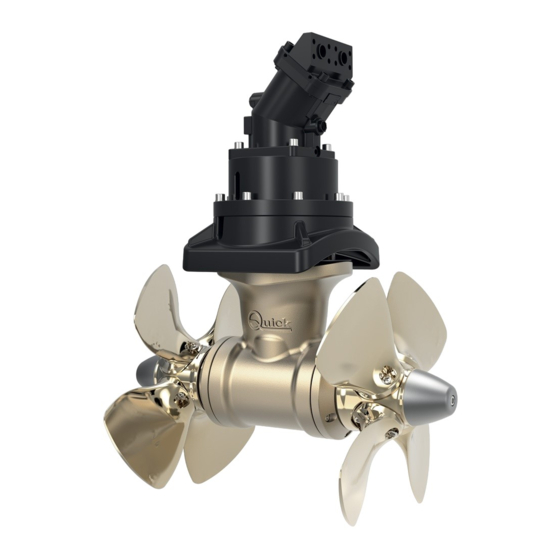
- Page 1 BTH 513 REV 001A DOPPIA ELICA DOUBLE PROPELLER ELICHE DI MANOVRA IDRAULICHE MANUALE D'INSTALLAZIONE E USO pag. 3 HYDRAULIC THRUSTERS INSTALLATION AND USE MANUAL pag. 19...
- Page 3 5.5 - Montaggio giunto/motore Pag. 13 6 - Collegamento elettrico Pag. 14 7 - Caratteristiche d'impianto Pag. 15 8 - Uso Pag. 15 9 - Manutenzione Pag. 16 Dimensioni Pag. 18 MANUALE D’INSTALLAZIONE ED USO QUICK BTH 513 - REV001A...
-
Page 4: Informazioni Sul Prodotto
Il motore idraulico delle eliche di manovra Quick è del tipo reversibile ad ingranaggi. La sua efficienza è condizionata dall’energia idrau- lica fornitagli dalla centrale oleodinamica cui è connesso. In particolare sarà influenzato dal numero di giri del motore principale, se è... - Page 5 • Le eliche di manovra Quick® sono state progettate e realizzate per asservire all’uso nautico. • Non utilizzare questi apparecchi per altri tipi di applicazioni. • Quick® non si assume alcuna responsabilità per i danni diretti o indiretti causati da un uso improprio dell’apparecchio o da una scorretta installazione.
- Page 6 • Per limitare le perdite di carico, la lunghezza consigliata è pari a 3-4 volte il diametro del tubo; è tollerato un rapporto fino a 6 volte il diametro. MANUALE D’INSTALLAZIONE ED USO QUICK BTH 513 - REV001A...
- Page 7 La grata deve avere maglie verticali e più larghe possibili, per non contrastare la spinta dell’elica. Le maglie verticali impediscono l’ingresso della maggior parte degli oggetti galleggianti. MANUALE D’INSTALLAZIONE ED USO QUICK BTH 513 - REV001A...
-
Page 8: Installazione
E’ necessario asportare con carta vetrata eventuali residui di re- sina e di tutti gli eventuali impedimenti al corretto contatto. MANUALE D’INSTALLAZIONE ED USO QUICK BTH 513 - REV001A... - Page 9 • Procedere al montaggio del piede riduttore. • Come ulteriore precauzione contro l’ingresso d’acqua, applicare silicone per uso nautico nella zona di contatto tra flangia e tubo. • Fissare la flangia utilizzando le specifiche viti. MANUALE D’INSTALLAZIONE ED USO QUICK BTH 513 - REV001A...
- Page 10 • Inserire nel raccordo il tubo rilsan con l’apposito • Dopo aver fissato la flangia girare in senso orario il rac- serbatoio dell'olio. cordo e allinearlo con lo scasso della flangia MANUALE D’INSTALLAZIONE ED USO QUICK BTH 513 - REV001A...
- Page 11 • Riempire il serbatoio dell’olio con olio per ingranaggi tipo GL-5 Centro del Tunnel POSIZIONARE IL TUBO CORRETTAMENTE IN MODO DA EVITARE L'EFFETTO "SIFONE". IL SERBATOIO DEVE SEMPRE RISULTARE IN POSIZIONE VERTICALE. Aria Olio MANUALE D’INSTALLAZIONE ED USO QUICK BTH 513 - REV001A...
- Page 12 A, fissare le eliche con i dadi autofrenanti D ed i grani E. Gli anodi F vanno bloccati con le viti G bagnate con adesivo strutturale (tipo loctite). ATTENZIONE: accertarsi, ad assemblag- gio ultimato, che l’elica sia ben centrata all’interno del tunnel. MANUALE D’INSTALLAZIONE ED USO QUICK BTH 513 - REV001A...
- Page 13 3 - Fissare la flangia motore con le 4 viti e rondelle in dota- zione. 4 - Inserire il motore sul giunto elastico, fissare con le 4 viti e rondelle in dotazione. MANUALE D’INSTALLAZIONE ED USO QUICK BTH 513 - REV001A...
-
Page 14: Collegamento Elettrico
Accessori Quick® per l’azionamento dell’elica di manovra idraulica. PCS TJ1 PCS TJ2 PCS TJ3 PCS DTW HOLD HOLD TCD 1044 TCD 1062 TCD 1022 TCD 1042 STERN Comando Interruttore interrutture di linea TSC di linea TMS MANUALE D’INSTALLAZIONE ED USO QUICK BTH 513 - REV001A... - Page 15 • Valori superiori possono compromettere irreparabilmente l’integrità del motore stesso. • Seguire attentamente le indicazioni di Quick per ottenere la massima efficienza dal vostro oggetto; in condizioni di regolazioni diverse, non superare i valori massimi di pressione indicati in tabella.
-
Page 16: Manutenzione
Rondelle vite flangia inf. motore Raccordo Serbatoio olio Tubo rilsan Flangia motore Guarnizione riduttore Chiavetta Piede riduttore Elica RH Elica LH Dado fissaggio elica Grani Puntale anodico Vite elica Tunnel 24 25 MANUALE D’INSTALLAZIONE ED USO QUICK BTH 513 - REV001A... - Page 17 BTH 513 9 - Manutenzione I Thruster Quick® sono costituiti da materiale resistenti all’ambiente marino: è indispensabile, in ogni caso, rimuo- vere periodicamente i depositi di sale che si formano sulle superfici esterne per evitare corrosioni e di conseguenza inefficienza del sistema.
- Page 18 Dimensioni 720 mm (28" 11/32 in) MANUALE D’INSTALLAZIONE ED USO QUICK BTH 513 - REV001A...
- Page 19 Pag. 28 5.5 - Coupling/Motor assembling Pag. 29 6 - Connection diagram Pag. 30 7 - System Characteristics Pag. 31 8 - Maintenance Pag. 31 9 - Usage Pag. 32 Dimensions Pag. 34 INSTALLATION AND USE MANUAL BTH 513 - REV001A...
-
Page 20: Information About The Product
TEXT IN THE ITALIAN LANGUAGE, REFERENCE WILL BE MADE TO THE ITALIAN TEXT. Quick thrusters’ hydraulic motor is a reversible gear-type motor. Its efficiency is a result of the power system it is connected to. It will be especially affected by the number of turns of the main motor, if this one feeds the pump, and/or the latter is supplying power to other hydraulic systems during bow thruster operation. -
Page 21: Supplied Parts
• Quick® Thrusters have been designed and constructed only for nautical use. • Do not use these appliances for other uses. • Quick® shall accept no responsibility for direct or indirect damages caused by improper use of the ap- pliance or an improper installation. - Page 22 • To limit losing thrust, the optimal length is equal to 3-4 times the tube diameter; a ratio of up to 6 can be tolerated. INSTALLATION AND USE MANUAL BTH 513 - REV001A...
- Page 23 The grating must have as large a vertical mesh as possible to avoid contrasting the propeller thrust. The vertical mesh prevents the entry of most of the floa- ting objects. INSTALLATION AND USE MANUAL BTH 513 - REV001A...
-
Page 24: Installation
• Take care that there are no resin residues in the contact area between flange and tube; this could cause misalignment. Any resin residues and any other hindrance to correct contact must be remo- ved by sandpaper. INSTALLATION AND USE MANUAL BTH 513 - REV001A... - Page 25 • For further protection against the entry of wa- ter, apply silicone for nautical use around the point of contact between flange and tube. • Fasten everything to the flange using the special screws. INSTALLATION AND USE MANUAL BTH 513 - REV001A...
- Page 26 5.2 - Rilsan Tube and oil tank • Insert the Rilsan pipe into the fitting with the spe- • After fixing the flange, turn the fitting clockwise and align it with the flange opening. cial expansion tank. INSTALLATION AND USE MANUAL BTH 513 - REV001A...
- Page 27 • Fill the oil tank with gear oil type GL-5 Tunnel center line POSITION THE PIPE CORRECTLY, IN ORDER TO PREVENT “SIPHON” EFFECT. THE TANK MUST ALWAYS END UP IN VERTICAL POSITION. INSTALLATION AND USE MANUAL BTH 513 - REV001A...
- Page 28 F soaked with building adhesive (such as Loctite). WARNING: on conclusion of assembly, make sure that the propellers are exactly positioned at the central point of the tunnel. INSTALLATION AND USE MANUAL BTH 513 - REV001A...
- Page 29 3 - Fix the motor flange with the 4 provided screws and washers. 4 - Insert the motor on the elastic coupling, fix with the 4 provided screws and washers. INSTALLATION AND USE MANUAL BTH 513 - REV001A...
-
Page 30: Connection Diagram
Quick® for activation of the hydraulic thruster. PCS TJ1 PCS TJ2 PCS TJ3 PCS DTW HOLD HOLD TCD 1044 TCD 1062 TCD 1022 TCD 1042 STERN TSC Thruster TMS Thruster main switch command main INSTALLATION AND USE MANUAL BTH 513 - REV001A... -
Page 31: System Characteristics
• Higher values may jeopardize irreparably the integrity of the motor itself. • Follow carefully Quick indications to obtain the highest efficiency from your product: in different setting condi- tions, do not exceed the maximum pressure values listed in the chart. -
Page 32: Maintenance
Lower washer screw flange Fitting Oil tank Rilsan tube Motor flange Garbox gasket Gearleg Propeller RH Propeller LH Propeller lock nut Tight screw Anode tip Anode tip mounting screw Tunnel 24 25 INSTALLATION AND USE MANUAL BTH 513 - REV001A... - Page 33 BTH 513 9 - Maintenance Quick® Thrusters are made in materials that are resistant to the sea environment: In any case, it is indispen- sable to periodically remove salt deposits that form on the outer surfaces to avoid corrosions and consequent system inefficiency.
- Page 34 Dimensions 720 mm (28" 11/32 in) INSTALLATION AND USE MANUAL BTH 513 - REV000A...
- Page 36 MANUALE D'INSTALLAZIONE ED USO INSTALLATION AND USE MANUAL Codice di serie del prodotto / Product code and serial number QUICK S.p.A. - Via Piangipane, 120/A - 48124 Piangipane (RAVENNA) - ITALY ® Tel. +39.0544.415061 - Fax +39.0544.415047 - www.quickitaly.com - quick@quickitaly.com...
Need help?
Do you have a question about the BTH 513 and is the answer not in the manual?
Questions and answers