
Subscribe to Our Youtube Channel
Related Manuals for Quick BTQR1806512


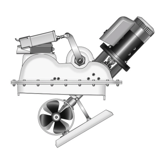
Summary of Contents for Quick BTQR1806512
- Page 1 REV 001 High Quality Nautical Equipment RETRACTABLE THRUSTER BTQR1806512 BTQR1806524 BTQR1808512 BTQR1808524 BTQR1810512 BTQR1810524 Manuale d'uso ELICHE DI MANOVRA RETRATTILI User's Manual RETRACTABLE THRUSTERS...
- Page 3 INDICE Pag. 4 - requisiti per l’installazione CARATTERISTICHE E INSTALLAZIONE Pag. 5 - posizionamento INSTALLAZIONE Pag. 6/7 - localizzazione dell’installazione INSTALLAZIONE Pag. 8 - verifica e regolazione del sistema INSTALLAZIONE Pag. 9 - taratura gruppo fine corsa INSTALLAZIONE Pag. 10 SCHEMA DI COLLEGAMENTO Pag.
- Page 4 è una semplice rivoluzione attorno al pivot principale bensì un movimento atto ad estromettere senza interferenze la piastra di chiusura dal foro praticato nello scafo. Motore elettrico, riduttore, leverismi e tutti gli altri componenti sono forniti da Quick ®...
-
Page 5: Installazione
INSTALLAZIONE Posizionamento minimo 0,75 volte Ø tunnel • Per evitare fenomeni di cavitazione nell’elica, si dovrà posizionare il tunnel più a fondo possibile. BARICENTRO • L’effetto di leva nell’imbarcazione è proporzionale all’aumento della distanza (L1 e L2) che si rileva, tra il baricentro e la posi- zione del tunnel A e B (poppa/prua). - Page 6 INSTALLAZIONE Localizzazione dell’installazione Accedere direttamente nella parte interna dello scafo, nella zona in cui il propulsore verrà installato. La posizione del propulsore dovrà permettere agevoli manovre di installazione. Fig. 1 PROPULSORE CHIUSO SCAFO PIASTRA METALLICA Posizionare il propulsore, in posizione di riposo (chiuso), all’interno dello scafo facendolo appoggiare sulla piastra metallica soli- dale al tunnel.
- Page 7 INSTALLAZIONE Realizzare l’apertura nello scafo, per il passaggio del tunnel, tagliando lo Fig. 4 scafo lungo il perimetro tracciato. Allineare il supporto alla posizione prestabilita e resinarlo, saldarlo nel caso Fig. 5 dell’alluminio o dell’acciaio, secondo le tecniche identificate come le più ido- nee al tipo di costruzione della carena.
- Page 8 INSTALLAZIONE VERIFICA E REGOLAZIONE DEL SISTEMA Fig. 7 La vite che permette la manovra manuale, si trova all’interno dell’attuatore, per accedervi togliere il tappo di protezione. Verificare il cinematismo del sistema di estromissione del tunnel manovrando manual- mente l’attuatore. Utilizzare un cacciavite per girare la vite dell’attuatore. Per aprire il coperchio girare la vite in senso orario.
- Page 9 INSTALLAZIONE Fig. 9a Realizzare secondo le più opportune tecniche un co- perchio di chiusura dell’apertura sulla carena e fissarlo al piatto metallico solidale al tunnel dell’unità retrat- tile. Fig. 9b Prestare particolare attenzione ad evitare interferenze tra il coperchio e l’apertura dello scafo. Contatti trop- po precisi provocheranno danni all’intero sistema di movimento.
- Page 10 SCHEMA DI COLLEGAMENTO ACCESSORI QUICK ® PER L'AZIONAMENTO DELL’ELICA RETRATTILE SISTEMA BASE BTQR18 PANNELLI DI COMANDO TCD 1022 TCD 1042 TCD 1044 TCD 1062 Esempio di collegamento TCD 1042 STERN INTERRUTTORE DI LINEA TMS TCD 1022 COMANDO INTERRUTTURE DI LINEA TSC...
- Page 11 AVVERTENZE - FUNZIONAMENTO/USO AVVERTENZE IMPORTANTI ATTENZIONE: accertarsi che non vi siano bagnanti ed oggetti galleggianti nelle vicinanze, prima di avviare l’elica retrattile. ATTENZIONE: si raccomanda, per non danneggiare il sistema, di non navigare con l’elica retrattile aperta. FUNZIONAMENTO / USO DELL’ELICA RETRATTILE Accensione L’accensione avviene in conseguenza all’attivazione di un pannello TCD.
-
Page 12: Manutenzione
MANUTENZIONE BTQR 1806512 BTQR 1806524 BTQR 1808512 BTQR 1808524 BTQR 1810512 BTQR 1810524 RETRACTABLE THRUSTER BTQR18 DP - IT GB - REV001A... - Page 13 POS. DENOMINAZIONE CODICE di manutenzione. Vite fissaggio motore MBV1025MXCEO Rondella fissaggio motore MBR10X000000 I Thruster Quick ® sono costituiti da materiale resistenti all’ambiente Motore 3KW 12V EMFEL3012000 marino: è indispensabile, in ogni caso, rimuovere periodicamente i Motore 3KW 24V EMFEL3024000...
- Page 14 Quick ® is able to supply stainless steel, aluminium alloy or GRP supports, fundamental for quick, solid and precise installation. For the fi breglass hulls the support must be laminate in the hull respecting the current Standards relating to joints. The pro- pulsion unit distributes mechanical stresses to the hull through the counter flange.
-
Page 15: Installation
INSTALLATION Positioning minimum 0,75 times Ø tunnel • To avoid cavitation in the propeller, the tunnel must be positioned as low as possible. BARYCENTRE • The lever effect in the boat is proportional to the distance increase (L1 and L2) detected between the barycentre and the position of tunnel A and B (bow/stern). - Page 16 INSTALLATION Installation positioning Directly access inside the hull, where the thruster will be installed. The thruster position must enable easy maintenance operations. Fig. 1 CLOSED THRUSTER HULL METAL PLATE Position the thruster in stand-by position (closed) inside the hull, making it rest on the metal plate integral to the tunnel. Detect the heights (X Y Z) between the lower part of the flange and the hull.
- Page 17 INSTALLATION Realise the opening in the hull for tunnel passage, by cutting the hull along the Fig. 4 outlined perimeter. Align the support to the pre-established position and resin it, weld it in case of Fig. 5 aluminium or steel, according to the techniques identified as most suitable for the type of hull construction.
- Page 18 INSTALLATION SYSTEM CHECK AND ADJUSTMENT Fig. 7 The screw enabling manual operation is found inside the actuator; to ac- cess, remove the protective cap. Check the kinematic of the expelling system of the tunnel by manually operating the actuator. Use a screwdriver to turn the actuator screw. Turn screw clockwise to open the lid.
- Page 19 INSTALLATION Fig. 9a According to the most opportune techniques, realise a closing lid of the opening on the hull and fix it to the solid metal plate to tunnel of the retractable unit. Fig. 9b Pay particular attention to avoid interferences between the lid and the hull opening.
-
Page 20: Connection Diagram
CONNECTION DIAGRAM QUICK ® ACCESSORIES FOR ACTIVATION OF THE RETRACTABLE THRUSTER BASIC SYSTEM BTQR18 CONTROL PANELS TCD 1022 TCD 1042 TCD 1044 TCD 1062 Connection example TCD 1042 STERN TMS THRUSTER MAIN SWITCH TCD 1022 TSC MAIN SWITCH COMMAND BLACK... - Page 21 WARNING - OPERATION/USAGE WARNING before starting the retractable thruster ensure there are no bathers and floating objects near-by. WARNING: to avoid damaging the system, it is recommended not to navigate with the retractable thruster open. WARNING: OPERATION / USE OF RETRACTABLE THRUSTER Start-up Start-up happens following activation of a TCD panel.
-
Page 22: Maintenance
MAINTENANCE BTQR 1806512 BTQR 1806524 BTQR 1808512 BTQR 1808524 BTQR 1810512 BTQR 1810524 RETRACTABLE THRUSTER BTQR18 DP - IT GB - REV001A... - Page 23 CODE carried out. Motor fixing screw MBV1025MXCEO Motor fixing washer MBR10X000000 Quick ® Thrusters are made in materials that are resistant to the 3KW 12V Motor EMFEL3012000 sea environment: In any case, it is indispensable to periodically 3KW 24V Motor...
- Page 24 ELICA DI MANOVRA RETRATTILE - DIMENSIONI mm (inch) RETRACTABLE THRUSTERS - DIMENSIONS BTQR18 599 (23 MOD. BTQR1806512 BTQR1806524 BTQR1808512 BTQR1808524 BTQR1810512 BTQR1810524 744 (29” 19/64) 744 (29” 19/64) 773 (30” 7/16) 744 (29” 19/64) 820 (32” 9/32) 820 (32” 9/32)
- Page 25 ELICA DI MANOVRA RETRATTILE - SISTEMA BASE RETRACTABLE THRUSTERS - BASIC SYSTEM TCD 1042 TCD 1022 BLACK BLACK BATTERY ISOLATOR MOTOR BATTERY 12/24V ELECTRONIC CONTROL CABLE BOARD DETAIL RTC BOARD EXTENSIONS (OPTIONALS) SPLITTER LED RED LED GREEN (OPTIONAL) TO THE SWITCH SERVICES TO THE SERVICES...
- Page 26 NOTES...
- Page 28 THRUSTER RETRACTABLE R001 BTQR185 Codice e numero seriale del prodotto Product code and serial number QUICK ® S.p.A. - Via Piangipane, 120/A - 48124 Piangipane (RAVENNA) - ITALY Tel. +39.0544.415061 - Fax +39.0544.415047 www.quickitaly.com - E-mail: quick@quickitaly.com...
Need help?
Do you have a question about the BTQR1806512 and is the answer not in the manual?
Questions and answers