
Related Manuals for Quick BT386HY455


Summary of Contents for Quick BT386HY455
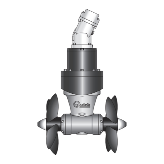
- Page 1 REV 001 High Quality Nautical Equipment HYDRAULIC THRUSTER BT386HY455 BT386HY580 Manuale d'uso ELICHE DI MANOVRA IDRAULICHE User's Manual HYDRAULIC THRUSTERS...
- Page 3 INDICE CARATTERISTICHE E INSTALLAZIONE Pag. 4 Pag. 5/6 INSTALLAZIONE - requisiti per l’installazione - il tunnel INSTALLAZIONE - il thruster Pag. 7 Pag. 8 INSTALLAZIONE - il piede e la flangia di supporto motore Pag. 9 INSTALLAZIONE - montaggio delle eliche - smontaggio flangia riduttore SCHEMA DI COLLEGAMENTO Pag.
- Page 4 CONSIGLIATI: TCD 1022 - TCD 1042 - TCD1044 - TCD1062 - TMS - TSC ® NOTA: Il motore idraulico delle eliche di manovra Quick è del tipo reversibile ad ingranaggi. La sua efficienza è condizionata dall’energia idraulica fornitagli dalla centrale oleodinamica cui è connesso. In particolare sarà...
-
Page 5: Requisiti Per L'installazione
INSTALLAZIONE REQUISITI PER L'INSTALLAZIONE IL TUNNEL • La posizione del tunnel dipenderà dalla forma interna ed esterna della prua della imbarcazione. • La sistemazione ottimale del tunnel, sarà più a prua e più a fondo possibile, minimo 0,75 volte il diametro del minimo 0,75 volte tunnel dalla linea di galleggiamento. - Page 6 INSTALLAZIONE • Le estremità arrotondate del tunnel limitano l’innesco di turbolenze e cavitazione, migliorando le prestazione della spinta dell’elica e riducendo al minimo la rumorosità. • Quando l’imbarcazione è in movimento, la forza prodotta dal flusso dell’acqua produce della resistenza sulla faccia posteriore del tunnel, che diventa un’area piatta al flusso dell’acqua.
- Page 7 INSTALLAZIONE IL THRUSTER • Il thruster può essere installato con qualunque angolo all’interno di 90º dalla verticale. • Il motore idraulico non necessita di supporti o sostegni. • Per posizionare correttamente il thruster trovare la mezzeria del tubo. • Utilizzare la flangia per contrassegnare sul tubo il cen- tro dei fori.
- Page 8 INSTALLAZIONE IL PIEDE RIDUTTORE E LA FLANGIA DI SUPPORTO MOTORE • Procedere al montaggio del piede riduttore con la spe- cifica guarnizione di tenuta. • Come ulteriore precauzione contro l’ingresso d’acqua, applicare silicone per uso nautico nella zona di contatto tra flangia e tubo.
-
Page 9: Pannello Di Comando
INSTALLAZIONE L’ELICA MONTAGGIO DELLE ELICHE Inserire le chiavette di trascinamento A nei fori sugli alberi del piede riduttore B, assemblare le eliche C al riduttore ingranandole alle chiavette di trascinamento A, fissare le eliche con i dadi autofrenanti D. Gli anodi E vanno bloccati con le viti F bagnate con adesivo strutturale (tipo loctite). -
Page 10: Schema Di Collegamento
SCHEMA DI COLLEGAMENTO SISTEMA BASE BTHY386 VALVOLA DISTRIBUTRICE DRENAGGIO MOTORE INGRESSO PRESSIONE ELICA DI MANOVRA IDRAULICA SERBATOIO ACCESSORI QUICK PER L'AZIONAMENTO ® DELL’ELICA DI MANOVRA IDRAULICA PANNELLI DI COMANDO TCD 1022 TCD 1042 TCD 1044 TCD 1062 STERN COMANDO INTERRUTTURE... -
Page 11: Avvertenze Importanti
• Valori superiori possono compromettere irreparabilmente l’integrità del motore stesso. • Seguire attentamente le indicazioni di Quick per ottenere la massima efficienza dal vostro oggetto; in condizioni di regolazioni diverse, non superare i valori massimi di pressione indicati in tabella. -
Page 12: Manutenzione
MANUTENZIONE BT 386HY455 BT 386HY580 BOW THRUSTER BTHY386 IT EN - REV001B... - Page 13 MANUTENZIONE I Thruster Quick sono costituiti da materiale resistenti all’am- ® biente marino: è indispensabile, in ogni caso, rimuovere perio- POS. DENOMINAZIONE dicamente i depositi di sale che si formano sulle superfici esterne per evitare corrosioni e di conseguenza inefficienza Vite fissaggio motore del sistema.
- Page 14 RICAMBI OSP KIT PARASTRAPPI D109 BT 386 FVSGGPVP1090A00 OSP KIT RICAMBIO GIUNTO BTQ 386 FVSGG3862532A00 OSP KIT RIDUTTORE BTQ386 FVSGGBBT3860A00 BOW THRUSTER BTHY386 IT EN - REV001B...
- Page 15 RICAMBI OSP KIT ELICA D386 RH FVSGEL386R00A00 OSP KIT ELICA D386 LH FVSGEL386L00A00 OSP KIT ANODI ELICA BTQ386 FVSGANBTQ386A00 BOW THRUSTER BTHY386 IT EN - REV001B...
- Page 16 ® NOTE: Quick thrusters’ hydraulic motor is a reversible gear-type motor. Its efficiency is a result of the power system it is connected to. It will be especially affected by the number of turns of the main motor, if this one feeds the pump, and/or the latter is supplying power to other hydraulic systems during bow thruster operation.
-
Page 17: Installation
INSTALLATION INSTALLATION REQUISITES: THE TUNNEL • The position of the tunnel will depend on the interior and exterior shape of the boats bow. • Optimal positioning of the tunnel will be in the bow and as low as pos- sible, at least 0.75 times the tunnel minimum 0.75 diameter from the waterline. - Page 18 INSTALLATION • The rounded ends of the tunnel limit the creation of turbulences and cavitations, improving performance of the propel- ler thrust and reducing noise levels to a minimum. • The force produced by the flow of the water when the boat is moving produces resistance on the rear face of the tunnel, which is an area exposed frontally to the water flow.
- Page 19 INSTALLATION THE THRUSTER • The thruster can be installed at any angle within 90° from vertical. • Il motore idraulico non necessita di supporti o sostegni. To position the thruster in the tube, find the half-way point. • Use the flange to mark the centre of the holes on the tube.
- Page 20 INSTALLATION GEARLEG AND MOTOR SUPPORT FLANGE • Proceed with fitting the gearleg with the special seal gasket. • For further protection against the entry of water, apply silicone for nautical use around the point of contact be- tween flange and tube. •...
-
Page 21: Control Panel
INSTALLATION PROPELLER PROPELLER FITTING Insert the Keys A into the hole on the gearleg shafts B; assemble the propeller C to the gearleg, making it fit in cor- rectly with the keys A; fix the propellers with the self-brak- ing nuts D. The anodes E must be locked with the screws F soaked with building adhesive (such as Loctite). -
Page 22: Connection Diagram
CONNECTION DIAGRAM BASIC SYSTEM BTHY386 SELECTOR VALVE DRAINAGE MOTOR PRESSURE INPUT HYDRAULIC THRUSTER TANK QUICK ACCESSORIES FOR ACTIVATION ® OF THE HYDRAULIC THRUSTER CONTROL PANELS TCD 1022 TCD 1042 TCD 1044 TCD 1062 STERN TSC THRUSTER MAIN SWITCH COMMAND PSS PARALLEL SERIES... -
Page 23: System Characteristics
• Higher values may jeopardize irreparably the integrity of the motor itself. • Follow carefully Quick indications to obtain the highest efficiency from your product: in different setting conditions, do not exceed the maximum pressure values listed in the chart. -
Page 24: Maintenance
MAINTENANCE BT 386HY455 BT 386HY580 BOW THRUSTER BTHY386 IT EN - REV001B... - Page 25 MAINTENANCE Quick Thrusters are made in materials that are resistant to the ® sea environment: In any case, it is indispensable to periodically POS. DESCRIPTION remove salt deposits that form on the outer surfaces to avoid corrosions and consequent system inefficiency.
-
Page 26: Spare Parts
SPARE PARTS OSP KIT EVEN TENSION DEVICE D109 BT 386 FVSGGPVP1090A00 OSP KIT JOINT SPARE BTQ 386 FVSGG3862532A00 OSP KIT GEARLEG BTQ386 FVSGGBBT3860A00 BOW THRUSTER BTHY386 IT EN - REV001B... - Page 27 SPARE PARTS OSP KIT PROPELLER D386 RH FVSGEL386R00A00 OSP KIT PROPELLER D386 LH FVSGEL386L00A00 OSP KIT PROPELLER ANODES BTQ386 FVSGANBTQ386A00 BOW THRUSTER BTHY386 IT EN - REV001B...
- Page 28 THRUSTERS DIMENSIONI / DIMENSIONS mm (inch) BTHY386 Ø 510 (20 BOW THRUSTER BTHY386 IT EN - REV001B...
- Page 29 THRUSTER SISTEMA BASE / BASIC SYSTEM VALVOLA DISTRIBUTRICE SELECTOR VALVE DRENAGGIO MOTORE DRAINAGE MOTOR ENTRATA PRESSIONE PRESSURE INPUT SERBATOIO TANK ELICA DI MANOVRA IDRAULICA HYDRAULIC THRUSTER BOW THRUSTER BTHY386 IT EN - REV001B...
- Page 30 NOTES...
- Page 32 THRUSTERS R001 BTHY386 Codice e numero seriale del prodotto Product code and serial number QUICK S.p.A. - Via Piangipane, 120/A - 48124 Piangipane (RAVENNA) - ITALY ® Tel. +39.0544.415061 - Fax +39.0544.415047 www.quickitaly.com - E-mail: quick@quickitaly.com...
Need help?
Do you have a question about the BT386HY455 and is the answer not in the manual?
Questions and answers