
Related Manuals for Quick BTR1806512


Summary of Contents for Quick BTR1806512
- Page 1 REV 004 High Quality Nautical Equipment RETRACTABLE THRUSTER BTR1806512 BTR1806524 BTR1808512 BTR1808524 BTR1810512 BTR1810524 ELICHE DI MANOVRA RETRATTILI Manuale d'uso RETRACTABLE THRUSTERS User's Manual...
- Page 3 INDICE Pag. 4 - requisiti per l’installazione CARATTERISTICHE E INSTALLAZIONE Pag. 5 - posizionamento INSTALLAZIONE Pag. 6/7 - localizzazione dell’installazione INSTALLAZIONE Pag. 8/9 - verifica e regolazione meccanica del sistema INSTALLAZIONE Pag. 10/11 - procedura di regolazione dell’interruttore di fine corsa di chiusura del propulsore BTR INSTALLAZIONE Pag.
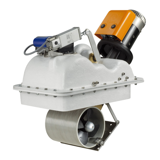
- Page 4 è una semplice rivoluzione attorno al pivot principale bensì un movi- mento atto ad estromettere senza interferenze la piastra di chiusura dal foro praticato nello scafo. Motore elettrico, riduttore, leverismi e tutti gli altri componenti sono forniti da Quick ®...
-
Page 5: Installazione
INSTALLAZIONE Posizionamento minimo 0,75 volte Ø tunnel • Per evitare fenomeni di cavitazione nell’elica, si dovrà posizionare il tunnel più a fondo possibile. BARICENTRO • L’effetto di leva nell’imbarcazione è proporzionale all’aumento della distanza (L1 e L2) che si rileva, tra il baricentro e la posizione del tunnel A e B (poppa/prua). - Page 6 INSTALLAZIONE Localizzazione dell’installazione Accedere direttamente nella parte interna dello scafo, nella zona in cui il propulsore verrà installato. La posizione del propulsore dovrà permettere agevoli manovre di installazione. Fig. 1 PROPULSORE CHIUSO SCAFO PIASTRA METALLICA Posizionare il propulsore, in posizione di riposo (chiuso), all’interno dello scafo facendolo appoggiare sulla piastra metallica solidale al tunnel.
- Page 7 INSTALLAZIONE Realizzare l’apertura nello scafo, per il passaggio del tunnel, tagliando lo Fig. 4 scafo lungo il perimetro tracciato. Allineare il supporto alla posizione prestabilita e resinarlo, saldarlo nel Fig. 5 caso dell’alluminio o dell’acciaio, secondo le tecniche identificate come le più...
- Page 8 INSTALLAZIONE VERIFICA E REGOLAZIONE MECCANICA DEL SISTEMA Realizzare secondo le più opportune tecniche un coperchio di chiusura dell’apertura sulla carena e fissarlo al piatto me- tallico solidale al tunnel dell’unità retrattile. Attenersi alla sequenza riportata di seguito per effettuare la verifi ca dell’apertura del portello: 1) Il propulsore BTR non deve essere alimentato.
- Page 9 INSTALLAZIONE L’ATTUATORE È GIÀ STATO PRE-TARATO IN FASE DI ASSEMBLAGGIO. NON MANOMETTERE TENTANDO GIRARE LE VITI PRESENTI SULLA TESTATA O RUOTANDO LO STELO DELL’ATTUATORE. RETRACTABLE THRUSTER BTR185 - IT GB - REV004B...
- Page 10 INSTALLAZIONE ATTENZIONE: prestare particolare attenzione ad evitare interferenze tra il coperchio e l’apertura dello scafo. Contatti troppo precisi provocheranno danni all’intero sistema di movimento. 3) Riagganciare l’attuatore alla leva inserendo il perno di blocco. Verifi cato meccanicamente il sistema procedere con la regolazione di fi ne corsa. PROCEDURA DI REGOLAZIONE DELL’INTERRUTTORE DI FINE CORSA DI CHIUSURA DEL PROPULSORE BTR ATTENZIONE: la seguente procedura deve essere eseguita da personale qualificato.
- Page 11 INSTALLAZIONE 9) Regolare il fine corsa sollevandolo verso l’alto (fig. 9 / part. A) facendo toccare la sua leva (B) sul cilindro dell’attuatore fino a che il LED LA STATUS diventerà di colore rosso. FIG. 9 FIG. 10 10) Fissare l’interruttore di fine corsa in questa posizione agendo sul- le viti di serraggio (fig.
-
Page 12: Schema Di Collegamento
SCHEMA DI COLLEGAMENTO ACCESSORI QUICK ® PER L'AZIONAMENTO DELL’ELICA DI MANOVRA RETRATTILE SISTEMA BASE BTR185 PANNELLI DI COMANDO TCD 1022 TCD 1042 TCD 1044 TCD 1062 Esempio di collegamento TCD 1042 STERN COMANDO INTERRUTTURE TCD 1022 DI LINEA TSC INTERRUTTORE BATTERIE... - Page 13 SCHEMA DI COLLEGAMENTO SCHEDA RTC R1 Nero RETRACTABLE THRUSTER BTR185 - IT GB - REV004B...
- Page 14 FUNZIONAMENTO / USO DIP-SWITCH SELEZIONE OPZIONI SWITCH FUNZIONE DESCRIZIONE Riservata (mantenere sempre OFF) 2 3 4 Indica alla stazione di comando CAN che il propulsore è di prua (OFF) Indica alla stazione di comando CAN che il propulsore è di poppa (ON) Riservata (mantenere sempre OFF) Riservata (mantenere sempre OFF) 1 2 3...
- Page 15 USO / SEGNALAZIONI Qualora sia richiesta una impostazione diversa da quella di fabbrica effettuare le seguenti operazioni: 1) Con la scheda non alimentata posizionare la freccia del selettore rotativo nella posizione voluta. 2) Alimentando la scheda, verrà automaticamente settata la percentuale corrispondente alla posizione selezionata. Se il limite di corrente/carico massimo è...
- Page 16 SEGNALAZIONI LED ERROR (rosso) NUMERO LAMPEGGI DESCRIZIONE Nessuna anomalia presente. NESSUNO Elevato assorbimento attuatore in salita (chiusura retrattile). La segnalazione avviene dopo che il sistema ha effettuato, in presenza di un attrito meccanico superiore alla soglia impostata, tre tentativi di risalita. Il problema può essere causato da un corpo estraneo entrato nel meccanismo, dall’imbarcazione in navigazione a velocità...
- Page 17 AVVERTENZE - FUNZIONAMENTO/USO AVVERTENZE IMPORTANTI ATTENZIONE: accertarsi che non vi siano bagnanti ed oggetti galleggianti nelle vicinanze, prima di avviare l’elica retrattile. ATTENZIONE: si raccomanda, per non danneggiare il sistema, di non navigare con l’elica retrattile aperta. ATTENZIONE: si raccomanda, per non danneggiare il sistema, di non abilitare l’elica a velocità superiori a quattro nodi.
-
Page 18: Manutenzione
MANUTENZIONE BTR 1806512 BTR 1806524 BTR 1808512 BTR 1808524 BTR 1810512 BTR 1810524 RETRACTABLE THRUSTER BTR185 - IT GB - REV004B... - Page 19 DENOMINAZIONE CODICE zioni di manutenzione. Vite fissaggio motore MBV1025MXCEO Rondella fissaggio motore MBR10X000000 I Thruster Quick ® sono costituiti da materiale resistenti all’am- Motore 3KW 12V EMFEL3012000 biente marino: è indispensabile, in ogni caso, rimuovere perio- Motore 3KW 24V EMFEL3024000...
- Page 20 Electric motor, gear, levers and all other components are supplied by Quick ®...
-
Page 21: Installation
INSTALLATION Positioning minimum 0,75 times Ø tunnel • To avoid cavitation in the propeller, the tunnel must be positioned as low as possible. BARYCENTRE • The lever effect in the boat is proportional to the distance increase (L1 and L2) detected between the barycentre and the position of tunnel A and B (bow/stern). - Page 22 INSTALLATION Installation positioning Directly access inside the hull, where the thruster will be installed. The thruster position must enable easy maintenance operations. Fig. 1 CLOSED THRUSTER HULL METAL PLATE Position the thruster in stand-by position (closed) inside the hull, making it rest on the metal plate integral to the tun- nel.
- Page 23 INSTALLATION Realise the opening in the hull for tunnel passage, by cutting the hull along Fig. 4 the outlined perimeter. Align the support to the pre-established position and resin it, weld it in Fig. 5 case of aluminium or steel, according to the techniques identified as most suitable for the type of hull construction.
- Page 24 INSTALLATION SYSTEM CHECK AND MECHANIC ADJUSTMENT According to the most opportune techniques, realise a closing lid of the opening on the hull and fix it to the solid metal plate to tunnel of the retractable unit. Follow the sequence described below to verify the opening of the hatch: The BTR propeller should be disconnected from power.
- Page 25 INSTALLATION THE ACTUATOR HAS ALREADY BEEN PRE-SET DURING ASSEMBLING. DO NOT TAMPER BY TRYING TO TURN THE SCREWS ON THE HEAD, OR BY ROTATING THE ACTUATOR’S STEM. RETRACTABLE THRUSTER BTR185 - IT GB - REV004B...
- Page 26 INSTALLATION WARNING: pay particular attention to avoid interferences between the lid and the hull opening. Too precise con- tacts will cause damages to the entire moving system. 3) Fix the actuator on the lever again, by inserting the lock pin. Once the system has been mechanically verifi...
- Page 27 INSTALLATION 9) Adjust the limit switch by lifting it upwards (fig. 9 / part A) making the lever (B) touch the actuator’s cylinder till the “LA STATUS” LED becomes red. FIG. 9 FIG. 10 10) Fix the limit switch in this position by operating on the tightening screws (fig.
-
Page 28: Connection Diagram
RTC R1 ELECTRONIC BOARD BATTERY 12/24V SPLITTER (OPTIONAL) TO THE SERVICES BATTERY FUSE 10A EXTERNAL QUICK ACTING F SWITCH LIMIT SWITCH TO THE SERVICES BATTERY ACTUATOR * COMMON NEGATIVE FOR THE BATTERY GROUPS. RETRACTABLE THRUSTER BTR185 - IT GB - REV004B... - Page 29 CONNECTION DIAGRAM RTC R1 BOARD Black RETRACTABLE THRUSTER BTR185 - IT GB - REV004B...
- Page 30 OPERATING / USAGE OPTION SELECTION DIP-SWITCH SWITCH FUNCTION DESCRIZIONE Reserved (always keep off) 2 3 4 Informs the CAN control station that the thruster is in the bow (OFF) Informs the CAN control station that the thruster is in the stern (ON) Reserved (always keep off) Reserved (always keep off) 1 2 3...
- Page 31 USAGE / NOTIFICATION SIGNS Should a setting different to the factory one be requested, carry out the following operations: 1) Turn the arrow of the rotary switch to the desired position with the board not powered. 2) When the board is powered, the percentage corresponding to the selected position will automatically be set. If the maximum current/load is too low compared to the real operating requirements, may intervene protections against high absorption of the actuator in closing and opening the retractable, with flashing 1 and 7 errors.
- Page 32 NOTIFICATION SIGNS LED ERROR (red) NUMBER OF DESCRIPTION FLASHING No anomaly present. NONE High absorption of the actuator during ascent (retractable thruster closing) Signalling occurs after the system has attempted three ascents in the presence of mechanical friction exceeding the set threshold. The problem can be caused by a foreign body that entered the mechanism, by the vessel navigating at sustained speed, or by mechanical problems of the retractable and relative hatch.
- Page 33 WARNING - OPERATION/USAGE WARNING WARNING: before starting the retractable thruster ensure there are no bathers and floating objects near-by. WARNING: to avoid damaging the system, it is recommended not to navigate with the retractable thruster open. WARNING: to prevent any damage to the system, do not enable the retractable thruster at a higher speed than four knots.
-
Page 34: Maintenance
MAINTENANCE BTR 1806512 BTR 1806524 BTR 1808512 BTR 1808524 BTR 1810512 BTR 1810524 RETRACTABLE THRUSTER BTR185 - IT GB - REV004B... - Page 35 CODE operations are carried out. Motor fixing screw MBV1025MXCEO Motor fixing washer MBR10X000000 Quick ® Thrusters are made in materials that are resistant to the 3KW 12V Motor EMFEL3012000 sea environment: In any case, it is indispensable to periodically 3KW 24V Motor...
- Page 36 ELICA DI MANOVRA RETRATTILE - DIMENSIONI mm (inch) RETRACTABLE THRUSTERS - DIMENSIONS BTR185 599 (23 MOD. BTR1806512 BTR1806524 BTR1808512 BTR1808524 BTR1810512 BTR1810524 708 (27” 7/8) 733 (28” 55/64) 779 (30” 45/64) A - mm (inch) B - mm (inch) 286 (11” 1/4) 313 (12”...
- Page 37 (OPTIONAL) DETAIL RTC R1 LED BI-COLOR TO THE SERVICES BOARD LA STATUS BATTERY LED RED ERROR RTC R1 BOARD FUSE 10A QUICK ACTING F SWITCH TO THE SERVICES BATTERY POWER LA STATUS ERROR 10 A EXTERNAL LA+ LA- LSC COM...
- Page 38 NOTES...
- Page 40 THRUSTER RETRACTABLE R004 BTR185 Codice e numero seriale del prodotto Product code and serial number QUICK ® S.P.A. - Via Piangipane, 120/A - 48124 Piangipane (RAVENNA) - ITALY Tel. +39.0544.415061 - Fax +39.0544.415047 www.quickitaly.com - E-mail: quick@quickitaly.com...
Need help?
Do you have a question about the BTR1806512 and is the answer not in the manual?
Questions and answers