
Related Manuals for Clarke METALWORKER CBS7MC


Summary of Contents for Clarke METALWORKER CBS7MC
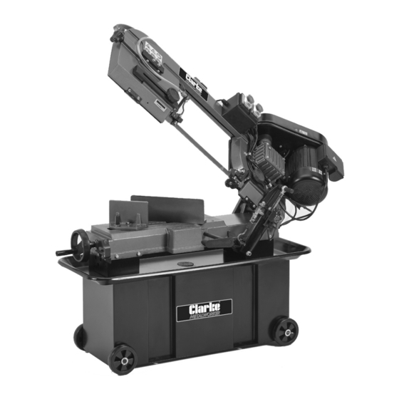
- Page 1 7” METAL CUTTING BANDSAW MODEL NO: CBS7MC PART NO: 6460123 OPERATION & MAINTENANCE INSTRUCTIONS ORIGINAL INSTRUCTIONS GC0922 Rev 1...
-
Page 2: Environmental Protection
INTRODUCTION Thank you for purchasing this CLARKE Bandsaw which is designed for DIY & light industrial use. Before attempting to operate the machine it is essential that you read this manual thoroughly and carefully follow all instructions given. In doing so you will ensure the safety of yourself and that of others around you and you can look forward to the product giving you long and satisfactory service. -
Page 3: Specifications
SPECIFICATIONS Weight 135kg Dimensions Folded Down (L x W x H) 1220 x 495 x 1001mm Dimensions Folded Up (L x W x H) 1220 x 495 x 1630mm Table Height from Floor 610mm Tilt Angle 0 - 45 Height: 180mm Maximum Cutting Capacity@0 Width: 270mm Height: 180mm... -
Page 4: Safety Symbols
SAFETY SYMBOLS Read the Wear eye Wear manual protection protective and safety mask instructions before use Wear ear Wear Disconnect protection protective from Power gloves Supply When Not in Use Warning: Warning: Warning: Electricity Sharp Risk of Blade Trapping Hand/ Fingers Parts &... -
Page 5: Safety Warnings
SAFETY WARNINGS CAUTION: FAILURE TO FOLLOW THESE PRECAUTIONS COULD RESULT IN PERSONAL INJURY, AND/OR DAMAGE TO PROPERTY. WORK ENVIRONMENT 1. Please read these instructions carefully and retain for future reference. 2. ALWAYS keep the work area clean and well lit. Cluttered and dark areas invite accidents. -
Page 6: Personal Safety
PERSONAL SAFETY 1. Stay alert, watch what you are doing and use common sense when operating a power tool. DO NOT use a power tool while you are tired or under the influence of drugs, alcohol or medication. A moment of inattention while operating power tools may result in personal injury. -
Page 7: Additional Precautions For Bandsaws
If damaged, have the power tool repaired before use. Many accidents are caused by poorly maintained power tools. If in doubt, DO NOT use the machine. Consult your local CLARKE dealer. 6. Machine cleanliness. DO NOT allow the ventilation slots in the machine/ motor to become blocked with dust. -
Page 8: Electrical Connections
ELECTRICAL CONNECTIONS WARNING! Read these electrical safety instructions thoroughly before connecting the product to the mains supply. Before switching the product on, make sure that the voltage of your electricity supply is the same as that indicated on the rating plate. This product is designed to operate on 230VAC 50Hz. - Page 9 OVERVIEW Item Description Item Description Blade Tension Handle Feed ON/OFF Valve Lever Blade Guide Adjustment Knob Lubricant Pump ON/OFF Switch Lubricant Control Valve Saw Motor ON/OFF Switch Blade Guides Vice Handwheel Motor Automatic Shut Off Switch Feed Rate Control Knob Blade Tracking Controls Parts &...
-
Page 10: Assembly Parts
ASSEMBLY PARTS Item Description Item Description Work Stop and Rod Hydraulic Cylinder 4 x 3mm x 30mm Cotter Pin Feed Rate Control Knob 4 x 5/8” Washer Feed ON/OFF Valve Lever Swarf Screen 4 x Wheel & Covers 2 x Wheel Axle Parts &... -
Page 11: Assembly And Setup
ASSEMBLY & SET UP The bandsaw comes partly assembled. Unpack and lay out all the items and identify each one, referring to pages 9 & 10. If any parts are missing, immediately contact the dealer where the product was purchased. CLEAN UP The unpainted surfaces of your machine are coated with a heavy duty rust preventative that prevents corrosion during shipment and storage. -
Page 12: Installing Work Stop
1. Unbolt the shipping bracket shown here. NOTE: Retain all components, as the bracket can be reinstated if the bandsaw needs transporting/ shipping in the future. INSTALLING WORK STOP 1. Insert the work stop rod through the hole in the base and lock in place with a hex key and screw. - Page 13 INSTALLING THE HYDRAULIC CYLINDER 1. Unscrew the retaining nut from the cylinder support rod and tighten the bolts that hold it to the side of the machine using a 17mm spanner. 2. Slide the cylinder onto the rod, as shown, with the feed rate control knob pointing upwards and refit the retaining nut into position at the end of the support rod.
-
Page 14: Installing The Wheels
INSTALLING THE WHEELS COMPONENTS & HARDWARE NEEDED • 4 x Wheels • 2 x Axle • 4 x Cotter Pins (3 x 30mm) • 4 x Flat Washers (5/8”) 1. Slide axle through the holes in the bottom of the cabinet. -
Page 15: Drive V-Belt
DRIVE V-BELT The drive belt may need to be tensioned or repositioned for your desired speed. 1. Disconnect the machine from the power supply. 2. Unscrew the cover to the pulley housing 3. Loosen the two hex bolts on the motor mount bracket, as shown. -
Page 16: Blade Selection
The Cutting Speed Rate Recommendation Chart that follows offers guidelines only for various metals, given in feet per minute (FPM) and meters per minute (MPM). Choose the speed closet to the number shown in the chart. Material Speed FPM (MPM) Material Speed FPM (MPM) Carbon Steel 196 - 354... - Page 17 TOOTH STYLE When selecting blades, another option to consider is the shape, gullet size, teeth set and teeth angle, otherwise known as Tooth Style. Many blade manufacturers offer variations of the four basic styles, as shown. • Standard: This style is considered to be the standard because the tooth size and shape are the same as the tooth gullet.
- Page 18 CHOOSING BLADE TPI Selecting the right blade for the job depends on a variety of factors, such as type, hardness and shape of the material being cut, machine capability and operator technique. The chart below is a basic starting point for choosing blade type based on teeth per inch (TPI) for variable tooth pitch blades and for standard raker type bi-metal blades/HSS blades.
-
Page 19: Operation
OPERATION STARTING & STOPPING The bandsaw has two start/stop buttons. One for the saw motor and one for the lubricant pump. They both have a spring loaded emergency stop cover, which should always be in the down position when the bandsaw is in operation. - Page 20 TO SQUARE VICE TO BLADE 1. Loosen the locking bolt, as shown. 2. Use the scale as a guide to set your angle, or a machinists square to square the blade to the vice. 3. Tighten the lock bolt. TO ADJUST VICE ANGLE 1.
-
Page 21: Blade Guides
BLADE GUIDES The blade guides should be positioned approximately 1/4” away from the workpiece if possible. This will help ensure straight cuts by keeping the blade from twisting and drifting off the cut line. To adjust the blade guides: 1. Loosen the blade guide knob as shown. -
Page 22: Blade Lubrication
3. Clamp workpiece in table vice. 4. Close the feed ON/OFF valve to lock the bow and blade a few inches above the workpiece. 5. With the correct saw blade and blade speed selected, turn the saw and lubricant pump ON. 6. -
Page 23: Maintenance
4. Replace the pump and slide the tank back into the base unit. 5. Replace the return hose back into the hole with the swarf screen basket. USING THE CUTTING LUBRICANT 1. Check that there is sufficient lubricant in the tank and the pump inlet is submerged. - Page 24 • Clean after each use • Check blade tension MONTHLY CHECK: • Lubricate vice screw (see below) • Check gear box lubrication (see page 25) CLEANING Cleaning the machine is relatively easy. Vacuum clean excess metal chips and sawdust, and wipe off the remaining dust with a dry cloth. If any resin has built up, use a resin dissolving cleaner to remove it.
-
Page 25: Blade Change
GEARS • Lube Type: NLGI#2 equivalent grease • Lube Amount: Thin coat • Lube Frequency: Every 90 Hours of operation TO LUBRICATE GEARS 1. Disconnect the machine from the power supply. 2. Remove the cover from the gearbox. 3. Using a small brush, apply a thin coat of grease to the headstock gears. - Page 26 2. Raise the bow of the bandsaw to the vertical position, close the feed ON/OFF valve to lock the bow in place and open the wheel access cover. 3. Remove the blade guards. 4. Turning anti-clockwise, loosen the blade tension handle, as shown, and slip the blade off the wheels.
-
Page 27: Blade Tension & Tracking
NOTE: It is possible to flip the blade inside out, in which case the blade will be installed in the wrong direction. Check to make sure the blade teeth are facing towards the workpiece, as shown. Some blades have a directional arrow as a guide. - Page 28 2. Using the blade tension controls, as shown, tension the blade to the required amount. 3. To fine tune the blade tension, use a blade tensioning gauge. TO ADJUST BLADE TRACKING ON BANDSAW The blade tracking has been correctly set at the factory. The tracking will rarely need to be adjusted if the bandsaw is used properly.
-
Page 29: Squaring The Blade
6. Adjust set screw with a 4mm hex wrench, then tighten hex bolt loosened in step 4. NOTE: Tightening the set screw will move the blade closer to the shoulder of the wheel. NOTE: Loosening the set screw will move the blade away from the shoulder. -
Page 30: Blade Guide Bearings
BLADE GUIDE BEARINGS The blade guide bearings come adjusted from the factory and the need for adjustment should rarely occur. Uneven blade wear and crooked cuts may be the results of improper adjustment. Each bearing assembly has an eccentric bushing that allows the distance between the blade and bearings to be adjusted. - Page 31 When storing the bandsaw, disconnect the power cable, cover the machine with a plastic sheet and store it in a dry location. REPLACEMENT BLADES & SUNDRIES Replacement blades and sundries are available from your CLARKE dealer; Blade (10tpi) 1 per pack Part no 1600772...
-
Page 32: Troubleshooting
TROUBLESHOOTING Bandsaw Operations Problem Check Solution Excessive blade 1. Material loose in vice. 1. Clamp work securely. breakage 2. Incorrect speed or feed. 2. Adjust speed or feed. 3. Blade pitch too great. 3. Replace with finer. toothed blade. 4. Material too hard. 4. - Page 33 Motor running too 1. Blade tension too high. 1. Reduce blade tension. 2. Drive belt too tight. 2. Reduce drive belt 3. Gears need lubrication. tension. 4. Blade is binding. 3. Check oil bath. 4. Decrease feed speed. Bad cuts (not 1.
- Page 34 Machine stalls or 1. Wrong Blade for workpiece 1. Use blade with correct is underpowered material. properties for your type of cutting. 2. Wrong workpiece material. 2. Use metal with correct properties for your type of cutting. 3. Feed rate/cutting speed 3.
-
Page 35: Parts List And Diagram
PARTS LIST & DIAGRAM DESCRIPTION DESCRIPTION Parts Diagram A Nut M10 Table Washer Adjusting Screw Lock Bolt Spacer Work Stop Rod Set Screw M6 x10 Work Stop Wheel Screw M6 x 12 Wheel Handle Lock Nut M10 Support Bracket Washer Dragging Handle Support Plate Washer 10... - Page 36 DESCRIPTION DESCRIPTION Nut M10 Drive Wheel Hex Bolt M8 x 30 Sliding Plate Wheel Rod Blade Tension Sliding Block Wheel Set Screw M8 x 20 Cotter Pin 2.5 x 25 Hex Bolt M8 x 40 Washer Washer Coolant Frame Washer Hose Hex Bolt M6 x 16 Hose...
- Page 37 DESCRIPTION DESCRIPTION Bearing Shaft Washer Support Plate Washer Washer Lock Nut M8 Hex Bolt M8 x 25 Guide Block, Rear Power Switch Cable Adjust Bracket, Front Power Cable Guide Block Assembly, Front Parts Diagram C Bracket for Hole Gearbox Assembly Guide Block, Front Gearbox Housing Blade Cover, Front...
- Page 38 DESCRIPTION DESCRIPTION Parts Diagram B Additions End Plate Screw Switch Switch Bracket Bolt Washer Screw Parts & Service: 020 8988 7400 / E-mail: Parts@clarkeinternational.com or Service@clarkeinternational.com...
- Page 39 PARTS DRAWING A Parts & Service: 020 8988 7400 / E-mail: Parts@clarkeinternational.com or Service@clarkeinternational.com...
- Page 40 PARTS DRAWING B Parts & Service: 020 8988 7400 / E-mail: Parts@clarkeinternational.com or Service@clarkeinternational.com...
- Page 41 PARTS DRAWING C Parts & Service: 020 8988 7400 / E-mail: Parts@clarkeinternational.com or Service@clarkeinternational.com...
- Page 42 DECLARATION OF CONFORMITY - UKCA Parts & Service: 020 8988 7400 / E-mail: Parts@clarkeinternational.com or Service@clarkeinternational.com...
-
Page 43: Declaration Of Conformity (Ce)
DECLARATION OF CONFORMITY - CE Parts & Service: 020 8988 7400 / E-mail: Parts@clarkeinternational.com or Service@clarkeinternational.com...
Need help?
Do you have a question about the METALWORKER CBS7MC and is the answer not in the manual?
Questions and answers