
Related Manuals for Clarke CBS45MD


Summary of Contents for Clarke CBS45MD
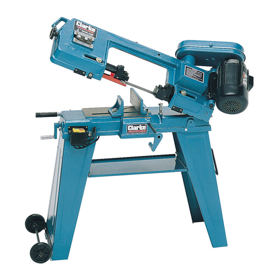
- Page 1 6” BANDSAW MODEL NO: CBS45MD PART NO: 6460060 OPERATION & MAINTENANCE INSTRUCTIONS ORIGINAL INSTRUCTIONS GC0614 - ISS 5...
-
Page 2: Environmental Protection
GUARANTEE This CLARKE product is guaranteed against faulty manufacture for a period of 12 months from the date of purchase. Please keep your receipt as proof of purchase. -
Page 3: Safety Warnings
SAFETY WARNINGS CAUTION: FAILURE TO FOLLOW THESE PRECAUTIONS COULD RESULT IN PERSONAL INJURY, AND/OR DAMAGE TO PROPERTY. WORK ENVIRONMENT 1. Keep the work area clean and well lit. Cluttered and dark areas invite accidents. 2. Do not operate power tools in explosive atmospheres, such as in the presence of flammable liquids, gases or dust. - Page 4 2. This machine is designed for indoor environments and must not be used for other purposes. 3. If the machine requires repair, always contact your Clarke dealer. Always insist on original spare parts. Repairs carried out by unauthorized persons may be dangerous and invalidate the guarantee.
-
Page 5: Additional Precautions For Bandsaws
2. Do not use the power tool if the switch does not turn it on and off. Any power tool that cannot be controlled with the switch is dangerous and must be repaired. 3. Disconnect the power tool from the power supply before making any adjustments, changing accessories, or storing the tool. -
Page 6: Specifications
7. Never use bent or cracked blades. (Replacement blades are available from your Clarke dealer. 8. When cutting wood, ensure all nails or fastenings have been removed beforehand. 9. When cutting round stock, use a suitable jig or fixture to keep the work from turning. -
Page 7: Electrical Connections
ELECTRICAL CONNECTIONS WARNING! Read these electrical safety instructions thoroughly before connecting the product to the mains supply. Before switching the product on, make sure that the voltage of your electricity supply is the same as that indicated on the rating plate. This product is designed to operate on 230VAC 50Hz. - Page 8 OVERVIEW Item Description Item Description Motor Blade Guide Carrier Lock Bolt Drive Guard Stop Bolt Blade Tension Adjusting Knob Vice Jaw Adjuster Blade Guides Manoeuvring Handle Blade Guide Carrier Lock Bolt Gearbox Blade Tracking Adjuster Drive Belt Tensioning Bolt Tool Tray Left Leg Adjustable Vice Jaw Right Leg...
- Page 9 ASSEMBLY The bandsaw comes partly assembled. Unpack and lay out all the items and identify each one, referring to the overview on page 8. If any parts are missing, immediately contact the dealer where the product was purchased. CAUTION: IF THERE IS ANY UNCERTAINTY REGARDING ELECTRICAL CONNECTIONS, YOU SHOULD CONSULT A QUALIFIED ELECTRICIAN.
-
Page 10: Drive Guard
DRIVE GUARD The drive guard sits over the motor shaft, and the gear-box shaft. The gearbox shaft extends through a circular plate secured by three screws. 1. Remove two of the screws (arrowed) and the guard fixing bolt. 2. Lower the drive guard over the shafts. -
Page 11: Drive Pulleys
DRIVE PULLEYS The drive pulleys may now be fitted. • The motor pulley is located with a key and grubscrew, and a keyway is therefore provided in the bore, whilst the gearbox pulley has no keyway, and is located with a grub-screw on a flat surface milled on the shaft. -
Page 12: Switch Assembly
SWITCH ASSEMBLY On the left end of the machine is the ON/OFF switch assembly, which is hanging loose at this stage. 1. Connect the two earth wires (1) extending from the back of the switch assembly to the machine bed using the screw and washer provided. - Page 13 2. Attach the wheel bracket to the base of the left leg using the nuts, bolts and washers, together with a pair of re-inforcing brackets fitted inside the leg. 3. Pass the axle through the holes at the ends of the bracket, and insert the split pins into the holes in the axle nearest the frame.
-
Page 14: Setup And Adjustments
SETUP AND ADJUSTMENTS BLADE GUIDE ADJUSTMENT The blade guides must be correctly aligned for the bandsaw to perform at its best. When the saw is used correctly, adjustment is rarely needed. If, for any reason, the guides do move out of alignment, you must re-adjust them immediately or the blade will not cut straight and will be damaged. -
Page 15: Adjusting Blade Tension
A general purpose blade (14 tooth per inch) is supplied with the saw (see Specifications). Additional blades,- in 14 and 24 tooth sizes are available from your local Clarke dealer. • The choice of blade pitch is governed by the thickness of the work to be cut:- the thinner the workpiece, the more teeth are used. -
Page 16: Changing Speed
CHANGING SPEED Always change the blade speed to suit the material being cut as shown in the chart below. 1. With the power disconnected, loosen the drive belt adjusting bolt in order to slacken the drive belt. 2. Open the drive guard and change the position of the belt to obtain the required speed. -
Page 17: Blade Tracking Adjustment
4. Remove the blade guard attached to the blade guide assembly. 5. Turn the blade tension adjuster knob anticlockwise to slacken the blade and allow removal from the pulleys and from between the guide bearings, paying due care to the sharpness of the teeth. 6. -
Page 18: Adjusting The Blade Angle
1. Disconnect from the power supply, set the saw arm is in the vertical position. 2. Open the blade safety cover and adjust the blade to moderate tension. 3. Slacken the two bolts, shown by one turn. 4. Turn the blade by hand, (taking care of sharp teeth), making sure that the blade runs closely against the lip on the back edge of the... -
Page 19: Methods Of Operation
METHODS OF OPERATION HORIZONTAL CUTTING 1. Raise the arm until held by the support bracket. 2. Open the vice by turning the handle at the end of the base anticlockwise. 3. Clamp the workpiece securely in the vice by turning the vice handle clockwise. -
Page 20: Vertical Cutting
VERTICAL CUTTING To operate in the vertical cutting position, the table must be fitted and the saw body locked in the vertical position. LOCKING IN THE VERTICAL POSITION 1. Rotate the vertical locking bracket to an upright position, and locate in the notch on the saw body. -
Page 21: Troubleshooting
TROUBLESHOOTING Problem Check Solution Excessive blade 1. Material loose in vice. 1. Clamp work securely. breakage 2. Incorrect speed or feed. 2. Adjust speed or feed. 3. Blade pitch too great. 3. Replace with finer. toothed blade. 4. Material too hard. 4. - Page 22 Motor running too 1. Blade tension too high. 1. Reduce blade tension. 2. Drive belt too tight. 2. Reduce belt tension. 3. Gears need lubrication. 3. Check oil bath. 4. Blade is binding. 4. Decrease feed speed. Bad cuts (not 1.
-
Page 23: Maintenance
MAINTENANCE WARNING: ALWAYS SWITCH OFF AND DISCONNECT FROM THE POWER SUPPLY BEFORE CARRYING OUT ANY CLEANING OR MAINTENANCE TASKS. GENERAL Remove all accumulated swarf from inside the bandsaw frequently using a soft brush and/or vacuum cleaner. Alternatively, if compressed air is used, ensure it is set to no more than 10 psi and wear protective safety glasses. -
Page 24: Parts List And Diagram
PARTS LIST & DIAGRAM NO DESCRIPTION NO DESCRIPTION Hexagon Headed Bolt SD450001 Hex Bolt SD45100 SD45002 Adjusting Bracket SD45057 Washer SD45003 Thumb Screw SD45058 Floor Stand (R/H) SD45004 Blade Safety Cover SD45059 Micro-switch SD45180 Circlip SD45060 Split Pin SD45006 Bearing SD45061 Stand Shelf SD45007... - Page 25 SD45109 Vertical Cutting Plate SD45055 When requesting replacement parts pleaase quote: SD45001 - 109. Replacement Blades and sundries are available from your Clarke dealer; Blade (14tpi) 1 per pack Part no 65009695 Blade (24tpi) 1 per pack Part no 65021135...
- Page 26 PARTS LIST & DIAGRAM Parts & Service: 020 8988 7400 / E-mail: Parts@clarkeinternational.com or Service@clarkeinternational.com...
-
Page 27: Declaration Of Conformity
DECLARATION OF CONFORMITY Parts & Service: 020 8988 7400 / E-mail: Parts@clarkeinternational.com or Service@clarkeinternational.com...
Need help?
Do you have a question about the CBS45MD and is the answer not in the manual?
Questions and answers