
Related Manuals for Clarke Woodworker CBS12WC


Summary of Contents for Clarke Woodworker CBS12WC
- Page 1 BANDSAW 12” & 14” (305mm) (355mm) Model Nos. CBS12WC & CBS14WC Part Nos. 6460070 & 6460050 OPERATING & MAINTENANCE INSTRUCTIONS 1/97...
-
Page 2: Table Of Contents
Bandsaw giving you long and trouble free service. GUARANTEE This CLARKE product is guaranteed against faulty manufacture for a period of 12 months from the date of purchase. Please keep your receipt which will be required as proof of purchase. This guarantee is invalid if the product is found to have been abused or tampered with in any way, or not used for the purpose for which it was intended. -
Page 3: General Safety Precautions
11. DRUGS, ALCOHOL, MEDICATION. Do not SAFETY PRECAUTIONS operate machine while under the influence of drugs, alcohol or any medication. GENERAL SAFETY RULES FOR OPERATING MACHINERY 12. USE RECOMMENDED ACCESSORIES. The use of improper accessories could be hazardous. WARNING: 13. NEVER LEAVE MACHINE RUNNING As with all machinery, there are certain hazards UNATTENDED. -
Page 4: Additional Safety Precautions For Bandsaws
ELECTRICAL INSTALLATION ADDITIONAL SAFETY RULES FOR BANDSAWS Connect the mains lead to a standard, 230 Volt (50Hz) electrical supply through an approved 13 amp BS Use a Push Stick or scrap of wood to do the • 1363 plug, or a suitably fused isolator switch. pushing and guiding, when sawing small pieces WARNING! THIS APPLIANCE MUST BE which require the fingers to be close to the blade. -
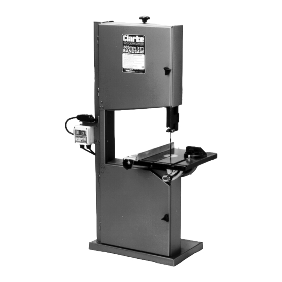
Page 5: Main Component Illustration
2. Motor Assembly Securing Knob. NOTE: This item is mounted on the back panel, 3. Switch Box Assembly on model CBS12WC, as indicated by the 4. (CBS12WC) Table Assembly c/w Trunnions dotted line. (CBS14WC) Table Assembly comprising: C Front Cover Securing Knobs... -
Page 6: Assembly
Tighten the motor mounting nuts firmly. C. THE TABLE 1. CBS12WC The table is shipped with the trunnions, tapered pin and table insert attached. Before installing, remove the taper pin, loosen the hex. head screws securing the trunnions to the under side of the table, and tap B. - Page 7 3. With the blade located in the centre hole, line up 2. CBS14WC the slotted holes of the larger rear trunnion, with The table assembly comprises three main comp- the long and short table tubes, and at the same onents, the table itself, a pair of trunnions, and the time position the slotted hole in the front trunnion trunnion base.
-
Page 8: Adjustments
D. ELECTRICAL CONNECTIONS ADJUSTMENTS 1. Switch Box A. BLADE ALIGNMENT AND TENSION On the left hand side of the frame, between the upper Blade tension is effected by raising or lowering the and lower wheel covers, are two loosely fitted screws. upper wheel, by means of the Blade Tension Adjuster These are the mountings for the switch box. - Page 9 Adjust carefully so that the blade runs smoothly This bearing should be set 1/64” (0.04mm) behind along the middle of the tyre, and lock the alignment the blade, and is adjusted by slackening the grub knob in place with the locknut on its threaded shaft. screw (E), positioning the bearing accordingly, and (see fig.
-
Page 10: Blade Renewal
If a reverse mitre is required, (up machine such as the CLARKE CDE35, as and to 15 ), it will be necessary to slacken the table stop when the need arises. -
Page 11: Tips On Bandsaw Use
Select a blade suitable for cutting the smallest radius in the work you have BEARINGS planned. See your CLARKE dealer for replacement All bearings used in the construction of your bandsaw or alternative blades. and its motor are sealed and lubricated for life. -
Page 12: Specifications
Dimensions ........610 x 480 x 1080 mm ..690 x 520 x 1210 mm Weight net/gross ....... 51 kg ........81.5 kg For Spare Parts and Servicing, please contact your nearest dealer, or CLARKE International, on one of the following numbers. PARTS - 0181 558 6696 SERVICE - 0181 556 4443... -
Page 13: Cbs12Wc
CBS12WC PARTS LIST No. Description Part No. No. Description Part No. Frame FMEBS12S001 Screw FMEBS12S061 Base FMEBS12S002 Screw FMEBS12S062 Pointer FMEBS12S063 Upper Wheel Box FMEBS12S003 Lower Wheel Box FMEBS12S004 Dust Outlet FMEBS12S064 Strengthener FMEBS12S005 Screw FMEBS12S065 Motor FMEBS12S066 Frame FMEBS12S006... -
Page 14: Cbs12Wc
PARTS DIAGRAM CBS12WC... -
Page 15: Cbs14Wc
PARTS LIST CBS14WC No. Description Part No. No. Description Part No. Spring 8mmx18 FMEBS14P61 Left Bracket Upper Housing. FMEBS14P01 Set Screw 3/8x3/8” FMEBS14P62 Right Bracket FMEBS14P02 Rod Lower Bearing Guide FMEBS14P63 Bracket Upper Mount FMEBS14P03 Trunnion Clamp Shoe FMEBS14P64 Bracket Upper Wheel FMEBS14P04 Screw FMEBS14P65... - Page 16 PARTS DIAGRAM CBS14WC...
- Page 17 PARTS DIAGRAM CBS14WC...
Need help?
Do you have a question about the Woodworker CBS12WC and is the answer not in the manual?
Questions and answers