
Related Manuals for Clarke CBS 190


Summary of Contents for Clarke CBS 190
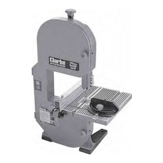
- Page 1 190mm (1½”) BANDSAW 190mm (1½”) BANDSAW Model: CBS 190 OPERATING & MAINTENANCE INSTRUCTIONS 0907...
-
Page 2: Parts And Service
Weight net/gross..............17.5/20 kg Part Number ................6460130 These specifications are correct at the time of going to print. Clarke International reserves the right to change specifications at any time in the inerests of safety or design change. PARTS and SERVICE Please contact your nearest dealer, or CLARKE International, on one of the following numbers. -
Page 3: Table Of Contents
Bandsaw giving you long and trouble free service. GUARANTEE This CLARKE product is guaranteed against faulty manufacture for a period of 12 months from the date of purchase. Please keep your receipt which will be required as proof of purchase. This guarantee is invalid if the product is found to have been abused or tampered with in any way, or not used for the purpose for which it was intended. -
Page 4: General Safety Precautions
Form the habit of checking to see that keys SAFETY PRECAUTIONS and adjusting wrenches are removed from the machine before switching on. GENERAL SAFETY RULES FOR OPERATING 11. DRUGS, ALCOHOL, MEDICATION. Do not MACHINERY operate machine while under the influence of drugs, alcohol or any medication. -
Page 5: Additional Safety Precautions For Bandsaws
ELECTRICAL INSTALLATION ADDITIONAL SAFETY RULES FOR BANDSAWS Connect the mains lead to a standard, 230 Volt (50Hz) electrical supply through an approved 13 • Set the blade guide block assembly as close amp BS 1363 plug, or a suitably fused isolator as possible to the workpiece. -
Page 6: Unpacking
Check to ensure that no damage was suffered Parallel (Rip) Fence in transit, and that all parts are accounted for. J Blade Tracking Adjuster You should contact your CLARKE dealer immediately, should there be any damage or K Table Insert deficiency... -
Page 7: Assembly
ASSEMBLY PREPARATION FOR USE All adjustments are factory set, except for those GENERAL NOTES: detailed below which MUST ALWAYS be checked For maximum stability and safety, the Bandsaw should before switching on the saw. be bolted firmly to either a workbench, a suitable stand, or a piece of plywood, 5/8”... -
Page 8: Operation
CLARKE CDE35, when the need arises. Slacken off the Guide Block using knob (L, Fig. 1) and adjust the height of the guide so that it is no Please see your CLARKE dealer for details. -
Page 9: Ripsawing
RIP SAWING This term refers to the cutting of the timber with Fig. 7 the grain, rather than at a right angles to the grain. You can rip wood freehand to a previously drawn line, but best results are obtained by using the rip fence. -
Page 10: Maintenance
5. Open the Wheel Cover using a screwdriver MAINTENANCE on each of the two knob centre screws 6. Ease the blade off the upper and lower ALWAYS disconnnect from the power supply wheels, taking care that the blade does not before carrying out any maintenance ‘spring’... -
Page 11: Blade Guide Adjustments
Fig. 12 Fig. 13 NOTE: exactly in the centre of the tyre. This adjustment Should you have difficulty in moving the tension is effected by turning the Tracking Adjuster Knob adjuster, it is possible that the Guide Screw, (arrowed (J, Fig. 11). in fig 14) is too tight. -
Page 12: Lower Blade Guides
Fig. 15 Simultaneously, slide the bearing to within 1/32” (0.4mm)of the back of the blade (shown in fig.16). Re-tighten screw (A) using the Hex. wrench provided when completely satisfied. 2. Lower Blade Guides Ref: Fig.18 The manner of adjustment is similar to that for the until the guides (C1) are positioned correctly. -
Page 13: Troubleshooting
Motor does not run 1. Renew fuse. If condition persists, consult your Clarke dealer 2. Plug or Power cable defective 2. Renew/Repair plug/Power cable 3. Consult your Clarke dealer 3. Motor defective Machine vibrates 1. Mountings loose 1. Tighten Mountings 2. Table loose 2. -
Page 14: Parts Lists & Diagrams
PARTS LIST & DIAGRAM No. Description Part No. No. Description Part No. Side Cover HT190001 Circlip HT190022 Hinge HT190002 Bearing HT190023 Side Cover Knob HT190003 Upper Blade Guard complete HT190024 Saw Blade HT190004 Lower Blade Guard complete HT190025 Rubber Tyre HT190005 Motor HT190027... -
Page 15: Specifications
When disposing of this product, do not dispose of with general waste. It must be disposed of according to the laws governing Waste Electrical and Electronic equipment, at a recognised disposal facility. © Copyright Clarke International. All rights reserved. November 1999.
Need help?
Do you have a question about the CBS 190 and is the answer not in the manual?
Questions and answers