
Related Manuals for Clarke CBS7MB


Summary of Contents for Clarke CBS7MB
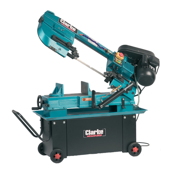
- Page 1 0514 7in. Metal Cutting Bandsaw 7in. Metal Cutting Bandsaw Model CBS7MB Part Number 6460122 Operating & Maintenance Instructions...
-
Page 2: Specifications
Angle Cut ..............0 - 45 Degrees Weight (unpacked) ............. 143kg net Noise Level (Sound Power Level) ........ less than 78dB Whilst Cutting. 1 Litres ....3051059 CLARKE CUTTING OIL Part No. 5 Litres ....3051061 Available from your Clarke dealer. DECLARATION OF CONFORMITY... -
Page 3: Table Of Contents
Thank you for purchasing your new Clarke Metal Cutting Bandsaw, designed for light industrial use ONLY. Before attempting to operate this bandsaw please read this instruction manual thoroughly and follow all directions carefully. This is for your own safety and that of others around you, and to ensure the machine will provide long and trouble free service. -
Page 4: General Safety Precautions
General Safety Precautions For Operating Machinery WARNING! As with all machinery, there are certain hazards involved with their operation and use. Exercising respect and caution will considerably lessen the risk of personal injury. However, if normal safety precautions are overlooked or ignored, personal injury to the operator or damage to machinery may result. -
Page 5: Additional Safety Precautions For Band Saws
✗ NEVER stand on the machine. Serious injury could occur if the machine is tipped over. Do not store materials above or near the machine such that it is necessary to stand on the machine to get to them. ✗ NEVER operate a machine when under the influence of alcohol, drugs or medication. -
Page 6: Electrical Connections
Electrical Connections Connect the mains lead to a standard 230V (50Hz) electrical supply through an approved 13Amp BS1363 plug, or a suitably fused isolator switch. WARNING! This Appliance must be Earthed! IMPORTANT: The wires in the mains lead are coloured in accordance with the following code: Green &... -
Page 7: Know Your Bandsaw
Know your Bandsaw Fig. 1 Blade Guide Carrier Lock Knob ON/OFF Switch Box Vise Jaw ON/OFF Coolant Pump Switch Band Saw Tracking Adjuster Motor Vise Jaw Adjuster Pulley Cover Work Stop Gearbox Hydraulic Ram Blade Tensioner Coolant Tank (inside base) Blade Guides (Accessed from rear) -
Page 8: Unpacking And Installation
Unpack your bandsaw and check to ensure it is undamaged. If damage has occurred during transit, you should notify your Clarke dealer immediately. Using appropriate tools, raise the saw sufficiently for blocks to be placed beneath, to allow the wheels to be fitted. -
Page 9: Overview
Prepare the Coolant Tank Fig. 5 Pull out Coolant Tank from the rear. Lift off the lid and fill with Clarke Cutting Oil, (see page 2), or Coolant (soluble oil), mixed according to the manufacturers recommendations. Do not allow to run dry. -
Page 10: Preparation For Use
Grasp the Arm and attempt to lower it, whilst simultaneously turning the knob ‘A’, anticlockwise. Turn the knob until the required rate of descent is achieved. The nut on the stem of Knob ‘A’ may be used to lock the valve in any particular position, thereby ensuring the rate of descent, and hence cutting pressure is constant - for repetitive work. -
Page 11: Setting The Blade Guides
Ref: Figs. 7 & 8 B. Adjusting the Blade Guides The blade guide adjustments are factory Fig. 7 set, and it should not normally be necessary to readjust unless maintenance, effecting the guides, has been carried out. See ‘Maintenance’ for details of adjustment. It is however MOST IMPORTANT that the Moveable Blade Guide Carriers (A) are set to ensure that the blade is... -
Page 12: The Work Stop
D. Setting the Work Stop Ref: Fig 2 The Work Stop may be used so that pieces of equal length may be cut, without having to measure each individual piece. With the workpiece set in the vice at the desired position, and firmly held in place, slacken off the grubscrew and bring the work stop up to the work, then retighten the grub screw, It is now a simple matter, once the first cut has been made, to open the vice jaws, slide the workpiece out until it touches the work... -
Page 13: Using The Bandsaw
To reposition the drive belt, proceed as follows: Ref: Figs. 11 & 12 REMEMBER to ensure the machine is disconnected from the mains supply. 1. To gain access to the drive belt, undo the screw securing the pulley cover, and open the cover, noting the microswitch mounted on the base of the casing. - Page 14 To switch OFF press the RED button Fig. 14 marked ‘O’, NOTE: If this is the first time you have operated your machine, or if a new blade has been installed, allow the blade to run completely off load for a few minutes to allow the blade to settle.
-
Page 15: Maintenance
MAINTENANCE WARNING! This machine MUST be disconnected from the mains supply whenever carrying out adjustments or maintenance of any kind. Fig. 16 A. Changing the Blade When the blade becomes worn or defective in any way it should be replaced immediately. The following process details how to change the blade, and should be carried out by a skilled technician only. -
Page 16: Blade Guide Bearing Adjustments
If the pulleys have not been interfered with, the blade should run evenly , running just off the lip on the back of each pulley. If it wanders off the pulleys, or bears heavily on the lip at the back of the pulley, evidenced by a harsh scraping sound, then tracking adjustment will be necessary - see page 17 B. -
Page 17: Blade Tracking Adjustment
(ii) Ensuring Blade is Square a. Slacken screw ‘C’ Fig.18 so that the carrier may be moved laterally, i.e. pivoted about screw ‘C’. b. Place an engineers square (arrowed in Fig.19) on the bed, as near as possible to the guide carrier, and bring up to the blade as shown in Fig.19. c. -
Page 18: Cleaning
D. Adjusting Arm Weight It is most important that the Arm be correctly balanced to ensure proper and efficient performance from your bandsaw. Incorrect balance can result in crooked cuts, tooth stripping, blade ‘popping’ etc. The hydraulic feed rate will NOT necessarily compensate for improper arm weight. -
Page 19: Troubleshooting
Troubleshooting Problem Remedy Possible Cause Excessive Blade Breakage 1. Incorrect blade tension 1. Adjust to where blade just does not 2. Incorrect speed or feed slip on wheel 3. Material loose in vice 2. Check Machinist Handbook 4. Blade rubs on wheel flange 3. -
Page 20: Parts Lists And Diagrams
Spare Parts List DESCRIPTION QTY PART NO. DESCRIPTION QTY PART NO. Table QB7MB001 Coolant Pan QB7MB051 Acme Screw QB7MB002 Filter QB7MB052 Washer QB7MB003 Hex. Hd. Screw QB7MB053 Hex. Socket Screw QB7MB004 Washer QB7MB054 Wheel QB7MB005 Hex. Nut QB7MB055 Hex Head Screw QB7MB006 Hex. - Page 21 Spare Parts List..cont. DESCRIPTION QTY PART NO. DESCRIPTION QTY PART NO. Hex. Head Screw QB7MB103 QB7MB154 Washer QB7MB104 Washer QB7MB155 Gearbox Cover QB7MB105 Hex Skt Screw QB7MB156 Gearbox Gasket QB7MB106 Deflector Plate QB7MB157 QB7MB107 Hd. Screw QB7MB158 Worm Gear QB7MB108 Bearing Shaft QB7MB159 Transmission Shaft...
- Page 22 Spare Parts Diagram...
- Page 23 Spare Parts Diagram Parts & Service contacts Please contact your nearest dealer, or CLARKE International, as follows: PARTS & SERVICE TEL: 020 8988 7400 PARTS & SERVICE FAX: 020 8558 3622 e-mail as follows: PARTS: Parts@clarkeinternational.com SERVICE: Service@clarkeinternational.com...
Need help?
Do you have a question about the CBS7MB and is the answer not in the manual?
Questions and answers