
Related Manuals for Clarke CBS300


Summary of Contents for Clarke CBS300
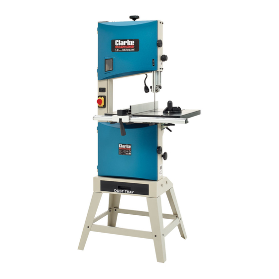
- Page 1 BANDSAW MODEL NO: CBS300/CBS350 PART NO: 6460077 / 6460078 OPERATION & MAINTENANCE INSTRUCTIONS GC1014...
-
Page 2: Environmental Protection
GUARANTEE This CLARKE product is guaranteed against faulty manufacture for a period of 12 months from the date of purchase. Please keep your receipt as proof of purchase. -
Page 3: Safety Warnings
SAFETY WARNINGS CAUTION: FAILURE TO FOLLOW THESE PRECAUTIONS COULD RESULT IN PERSONAL INJURY, AND/OR DAMAGE TO PROPERTY. WORK ENVIRONMENT 1. Keep the work area clean and well lit. Cluttered and dark areas invite accidents. 2. Do not operate power tools in explosive atmospheres, such as in the presence of flammable liquids, gases or dust. - Page 4 2. This machine is designed for indoor environments and must not be used for other purposes. 3. If the machine requires repair, always contact your Clarke dealer. Always insist on original spare parts. Repairs carried out by unauthorized persons may be dangerous and invalidate the guarantee.
- Page 5 2. Do not use the power tool if the switch does not turn it on and off. Any power tool that cannot be controlled with the switch is dangerous and must be repaired. 3. Disconnect the power tool from the power supply before making any adjustments, changing accessories, or storing the tool.
-
Page 6: Safety Symbols
7. Never use bent or cracked blades. (Replacement blades are available from your Clarke dealer. 8. Replace table insert if the slot has become enlarged. 9. When cutting wood, ensure all nails or fastenings have been removed beforehand. Nails will damage the saw blade. -
Page 7: Specifications
SPECIFICATIONS CBS300 CBS350 Weight 60.2 kg 76.8 kg Dimensions (W x D x H) 770 x 575 x 1586 mm 868 x 670 x 1705 mm Table Size (W x D) 480 x 390 mm 545 x 515 mm Throat Width... -
Page 8: Electrical Connections
ELECTRICAL CONNECTIONS WARNING! Read these electrical safety instructions thoroughly before connecting the product to the mains supply. Before switching the product on, make sure that the voltage of your electricity supply is the same as that indicated on the rating plate. This product is designed to operate on 230VAC 50Hz. - Page 9 OVERVIEW DESCRIPTION DESCRIPTION Blade Tension Setting Knob Fence Support Guide Rail Guide Height Setting Knob Drive Belt Setting Knob Adjustable Blade Guide Stop button Bandsaw Blade LED light switch Mitre Gauge Assembly Rip Fence Assembly Tilting Work Table Band Tensioner Viewing Window Parts &...
- Page 10 Ensure the bandsaw and its components suffered no damage during transit and that all components are present. Should any loss or damage be apparent, please contact your CLARKE dealer immediately. The following components are supplied with the bandsaw assembly. Item Description...
- Page 11 ASSEMBLY 1. Rest the bandsaw assembly on its side, supported by a block of timber as shown. • Protect the upper casing from damage with cardboard or rag where it lays on the ground. 2. Attach the legs using the M8 x 12 socket head bolts and 8 mm flat washers.
- Page 12 6. Secure the guide rail to the table with the four locking knobs. 7. Fit the tool set holder to the machine frame using the M4x10 screws. Install the loose tools (4 x hex keys and a spanner). 8. Fit the push stick hook to the side of the machine and tighten using the unique locking nut.
- Page 13 ADJUSTING THE PARTS TILTING THE TABLE 1. Loosen the locking handle and turn the table tilting knob to adjust the table to the desired angle. 2. Use the angle indicator scale on the table tilting bracket, to find the desired angle. 3.
- Page 14 ADJUSTING THE BLADE TENSION CAUTION: TOO MUCH TENSION CAN CAUSE THE SAW BLADE TO BREAK. TOO LITTLE TENSION CAN CAUSE THE BLADE TO MAKE IRREGULAR CUTS 1. Raise the upper blade guide fully. 2. Check the tension by pressing with a finger against the side of the blade, halfway between the table and upper guide.
- Page 15 UPPER BLADE GUIDE ADJUSTMENT GUIDE HEIGHT The height of the blade guide needs to be adjusted prior to every cutting operation to accommodate the height of the workpiece. The upper blade guide should be set approx 3 mm above the workpiece. 1.
- Page 16 ALIGNING THE LOWER BLADE GUIDE The lower blade guide needs to be re-adjusted after any blade change or tracking adjustment. • This task may be easier if the table is tilted for better access. 1. Loosen the screw (D), and move the entire lower blade guide.
-
Page 17: Changing The Saw Blade
3. Put the driving belt on the required pulley of the driving wheel (lower band-saw wheel) and the corresponding motor pulley. 4. Turn the belt tension knob to adjust the belt tension. • Turn clockwise to reduce tension/ counter -clockwise to increase tension. - Page 18 4. Loosen the quick-release lever until the band saw blade has slackened. 5. Remove the saw blade from the machine. 6. Fit a fresh saw blade and centre the blade on the rubber tyres of the wheels. 7. Tighten the quick release lever. 8.
- Page 19 THE RIP FENCE The rip fence can be used on both sides of the blade. When the fence is re-located from one side to the other, it needs to be reversed as follows. REVERSING THE FENCE 1. Loosen and remove the two knobs.
- Page 20 • The fence can be adjusted for accuracy when parallel to the side of the blade by loosening the two socket bolts (H). Check the alignment with a square before tightening the bolts. ALIGNING THE FENCE WITH THE BLADE To determine the distance of the fence from the saw blade, the scale on the fence guide rail must be set to line up with the blade.
- Page 21 CONNECTING TO A DUST COLLECTOR This bandsaw is fitted with a dust port for connection to a dust collector if available. Connections are available in the following sizes: • 50mm o/d • 75mm o/d • 100mm o/d Other sawdust will fall into the dust drawer which can be removed and emptied as required.
- Page 22 Plan your cut so that the kerf is the scrap side of the line you wish to cut. Where necessary, allow a little more material for finishing. • Always use a suitable holding device when cutting round or irregular shaped timber to prevent twisting of the work piece. TYPES OF CUT Several types of cut are possible with this saw i.e.
- Page 23 MAINTENANCE WARNING: ALWAYS SWITCH OFF THE MACHINE AND DISCONNECT FROM THE POWER SUPPLY BEFORE CARRYING OUT ANY CLEANING OF MAINTENANCE TASKS. CLEANING Accumulated dust and chips should be removed from inside the bandsaw frequently as well as emptying the dust drawer. Open the upper and lower covers, use a soft brush and/or vacuum cleaner to remove sawdust.
-
Page 24: Troubleshooting
7. Blade is badly welded or 7. Renew blade brazed. 8. Wrong blade fitted. 8. Fit only quality blades 9. Bandsaw left running when supplied by your Clarke not in use. dealer. 9. Always switch machine off when not in use. Noise or vibration 1. -
Page 25: Parts Diagram
PARTS DIAGRAM Parts & Service: 020 8988 7400 / E-mail: Parts@clarkeinternational.com or Service@clarkeinternational.com... - Page 26 PARTS DIAGRAM Parts & Service: 020 8988 7400 / E-mail: Parts@clarkeinternational.com or Service@clarkeinternational.com...
-
Page 27: Parts List
PARTS LIST PART NO DESCRIPTION PART NO DESCRIPTION 5 x 12 socket head screw 35 ## Wheel Tread 5 mm Washer 36 ## Saw Blade Blade Tension Knob 37 ## Upper Cover Panel 4 ## Blade Tensioner Screw Window Glass Spacer Window Seal 3AMI-15 Circlip... - Page 28 PART NO DESCRIPTION PART NO DESCRIPTION 8 mm Flat Washer Spring Pin Brush Spacer 107 ## Guard Plate 8 mm Flat Washer 6 x 12 mm Socket Head Screw Dust Brush Connecting Block 8 x 90 mm Square Head Bolt Connecting Shaft 20 x 1.5 mm Nut 6 x 8 mm Socket Set Screw...
- Page 29 PART NO DESCRIPTION PART NO DESCRIPTION 6 x 10 mm Set Screw 4 mm Flat Washer 6 mm Flat Washer Pointer Lower Guide Block 6 mm Flat Washer 6 x 8 mm Socket Head Bolt 6 x 10 Bolt 5 x 10 mm Socket Head Bolt 8 mm Flat Washer 5 x 25 mm Socket Head Bolt 8 x 10 Socket Head Bolt...
- Page 30 Long Support Beam 4 mm Hex (Allen) Key Supporting Leg 3 mm Hex (Allen) Key 6 mm Nut Items marked ## must be specified according to whether CBS300 or 350 model. Parts & Service: 020 8988 7400 / E-mail: Parts@clarkeinternational.com or Service@clarkeinternational.com...
-
Page 31: Declaration Of Conformity
DECLARATION OF CONFORMITY Parts & Service: 020 8988 7400 / E-mail: Parts@clarkeinternational.com or Service@clarkeinternational.com...
Need help?
Do you have a question about the CBS300 and is the answer not in the manual?
Questions and answers