
Related Manuals for Clarke WOODWORKER CBS250


Summary of Contents for Clarke WOODWORKER CBS250
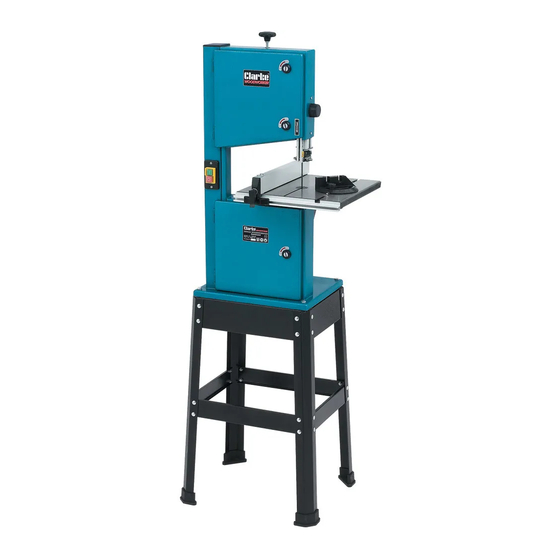
- Page 1 245 MM (10”) BANDSAW & STAND 245 MM (10”) BANDSAW & STAND MODEL No. CBS250 Part No. 6460135 Part No. 6460200 OPERATING & MAINTENANCE INSTRUCTIONS 0604...
- Page 3 Service@clarkeinternational.com Please note that the details and specifications contained herein are correct at the time of going to print. However CLARKE International reserve the right to change specifications at any time without prior notice. Always consult the machines data plate...
-
Page 4: Specifications
NOTES CONTENTS SPECIFICATIONS -19-... -
Page 5: Parts List
IMPORTANT: ALWAYS keep your proper footing and balance at all he use of parts other than CLARKE replacement parts may result in safety hazards, times don’t overreach. For best footing, wear rubber decreased tool performance and may invalidate your warranty. -
Page 6: Additional Precautions For Bandsaws
DO NOT use bent or cracked blades. Replacement blades are available from your CLARKE dealer. Replace table insert if slot has become enlarged. 10. When cutting wood, ensure all nails have been removed beforehand. Nails will damage the saw blade. -
Page 7: Electrical Connections
Parts List ELECTRICAL CONNECTIONS his product is fitted with a standard 13 amp, 230 volt (50Hz), BS 1363 plug, for connection Item Part No Description to a standard, domestic electrical supply. Should the plug need changing at any time, ensure that a plug of identical specification is used. WARNING ! THIS APPLIANCE MUST BE EARTHED This machine must be wired up in accordance with the following colour code: BLUE... -
Page 8: Unpacking The Machine
UNPACKING THE MACHINE Parts Diagram When lifting etc, always seek assistance from an able bodied person wherever possible, also when seeking assistance, you must ensure that you explain carefully where and when to lift, the weight, where it is going to be placed etc, it is important you that you take complete charge and give clear and precise instructions. - Page 9 Fig. 5 IMPORT ANT: through the centre of the table insert. he use of parts other than CLARKE replacement parts may result in safety hazards, • decreased tool performance and may invalidate your warranty. ighten the securing screws, and check saw blade still runs in the centre of the table insert, if not carry out the adjustment again.
-
Page 10: Maintenance
Mitre Cutting Fit the aluminium profile with scale, to the front of the table using four bolts and washers supplied, Most crosscut work, especially with small pieces ensure the cut out in the aluminium carrier is lined is more easily controlled with the use of a mitre up with the ‘T’... - Page 11 Use both hands to feed the workpiece in to the blade. The work must be held flat on tracks in the wrong direction, turn the handwheel in opposite direction. the table at all times to prevent binding of the blade. Use a steady even pressure just When tracking is achieved, lock the handwheel by turningthe lock clockwise.
-
Page 12: Operation
Changing the Sawblade. it almost touches leaving a gap of no less Upper Blade Guides than 0.5mm. Tighten the grub screw. Ensure the machine is switched OFF, and isolated from the main electrical supply by • removing the plug from the 13amp socket. Loosen grub screw ‘B’...
Need help?
Do you have a question about the WOODWORKER CBS250 and is the answer not in the manual?
Questions and answers