Clarke Metalworker CBS45MD Operating & Maintenance Manual
6” (152mm) bandsaw
Hide thumbs
Also See for Metalworker CBS45MD:
- Operation & maintenance instructions manual (29 pages)

Related Manuals for Clarke Metalworker CBS45MD


Summary of Contents for Clarke Metalworker CBS45MD
- Page 1 6” (152mm) BANDSAW 6” (152mm) BANDSAW MODEL CBS45MD OPERATING & MAINTENANCE INSTRUCTIONS 0707...
-
Page 2: Specifications
Waste Electrical and Electronic equipment, at a recognised disposal facility. Parts & Service contacts Please contact your nearest dealer, or CLARKE International, as follows: PARTS & SERVICE TEL: 020 8988 7400 PARTS & SERVICE FAX: 020 8558 3622 e-mail as follows: PARTS: Parts@clarkeinternational.com... -
Page 3: Table Of Contents
Thank you for purchasing your new Clarke Metal Cutting Bandsaw, designed for light industrial use ONLY. Before attempting to operate this bandsaw please read this instruction manual thoroughly and follow all directions carefully. This is for your own safety and that of others around you, and to ensure the machine will provide long and trouble free service. -
Page 4: General Safety Precautions
General Safety Precautions For Operating Machinery WARNING! As with all machinery, there are certain hazards involved with their operation and use. Exercising respect and caution will considerably lessen the risk of personal injury. However, if normal safety precautions are overlooked or ignored, personal injury to the operator or damage to machinery may result. -
Page 5: Additional Safety Precautions For Band Saws
✗ NEVER stand on the machine. Serious injury could occur if the machine is tipped over. Do not store materials above or near the machine such that it is necessary to stand on the machine to get to them. ✗ NEVER operate a machine when under the influence of alcohol, drugs or medication. -
Page 6: Electrical Connections
Electrical Connections Connect the mains lead to a standard 230V (50Hz) electrical supply through an approved 13Amp BS1363 plug, or a suitably fused isolator switch. WARNING! This Appliance must be Earthed! IMPORTANT: The wires in the mains lead are coloured in accordance with the following code: Green &... -
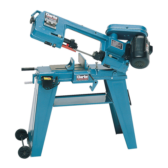
Page 7: Know Your Bandsaw
Know your Bandsaw Fig. 1 Blade Guide Carrier Lock Bolt Motor Work Stop Pulley Cover Blade Tensioner Vise Jaw Adjuster Blade Guides Manouvering Handle Blade Guide Carrier Lock Bolt Gearbox Drive Belt Adjuster Bolt Band Saw Tracking Adjuster Left leg Vise Jaw Adjustable Vise Jaw Right leg... -
Page 8: Assembly
Assembly IMPORTANT! This machine cannot be handled without the use of lifting tools. Take all necessary precautions when manoeuvring. For ease of packing and transportation, the bandsaw comes partly assembled. It is therefore necessary to complete the assembly as follows. Unpack and lay out all the items and identify each one by referring to the Parts List and Fig. - Page 9 before mounting the pulley cover. Having done so, lower the Pulley Cover over the shafts, ensuring the elongated hole is over the motor shaft. Replace the screw removed earlier through the pulley cover, into its hole in the circular plate. (This screw now locates and secures the pulley cover at the gearbox shaft).
- Page 10 with the smallest diameter inwards, and the gearbox pulley with the smallest diameter outwards (as illustrated in the Parts Diagram). Locate the gearbox pulley on to its shaft, ensuring the grub screw lines up with the flat on the shaft. Tighten the grub screw fully. Fit the motor pulley to its shaft so that it lines up with the gearbox pulley.
-
Page 11: Adjustments And Maintenance
Thread the ends of the handle through the corresponding holes in the right leg, and locate on the inside of the leg using the split pins provided. The wheel assembly comprises a bracket, axle and wheels. Attach the bracket to the base of the left leg using the nuts and bolts supplied. -
Page 12: Blade Guide Assembly Adjustment
2. BLADE GUIDE ASSEMBLY ADJUSTMENT The Metal Cutting Bandsaw is equipped with two adjustable blade guide assemblies, so that the blade guides may be individually adjusted to accommodate various widths of workpieces. To effect the most accurate cut and prolong the life of the blade, the blade guide assemblies should be adjusted to just clear the piece to be cut without impeding the lowering arm. -
Page 13: Changing Blade Speed
5. CHANGING SPEED When using your Bandsaw always change the blade speed to best suit the material being cut. The material cutting chart in shown below. With the power disconnected, loosen the Drive Belt Adjuster Bolt (item P) in order to slacken the drive belt, then open the pulley cover and change the position of the belt to gain the desired speed. -
Page 14: Blade Tracking Adjustment
4. Carefully feed the new blade between the blade guide bearings, ensuring the teeth are pointing DOWNWARDS, and then over the top pulley. Hold in position with one hand whilst stretching the blade downwards, and over the bottom pulley. Hold in place whilst applying slight tension by screwing the blade tension adjuster knob clockwise. -
Page 15: Adjusting Blade Angle
8. ADJUSTING BLADE ANGLE When horizontal cutting, the blade must be at right angles (or vertical) to the bed. To achieve this: Loosen the screw (A, Fig.4). Adjust the blade guide (B, Fig.4) to make the blade vertical to the bed. Place can engineers square on the bed to check the blade Is vertical, It not, repeat the process. -
Page 16: Methods Of Operation
Method Of Operation HORIZONTAL CUTTING Raise the arm to the vertical position. Open the vice to accept the piece to be cut by rotating the wheel at the end of the base anticlockwise. Place the workpiece on the saw bed. If the piece Is long it should be supported. Clamp the workpiece securely in the vice by turning the hand wheel clockwise. -
Page 17: Troubleshooting
Trouble Shooting Symptom Possible Cause(s) Corrective Action Excessive Blade 1. Material loose in vice. 1. Clamp work securely. Breakage. 2. lncorrect speed or feed 2. Adjust speed or feed. 3. Blade pitch too large. 3. Replace with finer tooth blade. 4. -
Page 18: Parts Lists And Diagrams
Parts List No. Description Part No. Qty No. Description Part No. Qty 39 Vertical Cutting Plate SD45039 Motor SD45001 40 Vert Cutting Plate Supp’t SD45040 Motor Pulley SD45002 41 Bush SD45041 2A Motor Pulley Grubscrew SD45002A 1 42 Blade Wheel Left SD45042 Motor Pulley Cover SD45003... - Page 19 Parts Diagram...
Need help?
Do you have a question about the Metalworker CBS45MD and is the answer not in the manual?
Questions and answers