
Related Manuals for Clarke CBS 355


Summary of Contents for Clarke CBS 355
- Page 1 360mm (14") 360mm (14") BAND SAW BAND SAW Model No. CBS 355 Part No. 6460080 Operating and Maintenance Instructions 1003...
-
Page 2: Specifications
Net / Gross Weight ............. 30 / 32 kg (65 - 70lbs) SPARE PARTS AND SERVICE CONTACTS For Spare Parts and Service, please contact your nearest dealer, or CLARKE International, on one of the following numbers. PARTS & SERVICE TEL: 020 8988 7400 PARTS & SERVICE FAX: 020 8558 3622 e-mail as follows: PARTS: Parts@clarkeinternational.com... -
Page 3: Table Of Contents
Bandsaw. GUARANTEE This CLARKE product is guaranteed against faulty manufacture for a period of 12 months from the date of purchase. Please keep your receipt which will be required as proof of purchase. This guarantee is invalid if the product is found to have been abused or tampered with in any way, or not used for the purpose for which it was intended. - Page 4 GENERAL SAFETY RULES FOR OPERATING MACHINERY WARNING: As with all machinery, there are certain hazards involved with their operation and use. Exercising respect and caution will considerably lessen the risk of personal injury. However, if normal safety precautions are overlooked or ignored, personal injury to the operator or damage to property, may result.
- Page 5 • • MAINTAIN MACHINE IN TOP ALWAYS ensure that ADEQUATE LIGHTING is CONDITION. available. A minimum intensity of 300 lux should be Keep tools sharp and clean provided. Ensure that lighting is placed so that you will for the best and safest not be working in your own shadow.
-
Page 6: Additional Safety Precautions For Bandsaws / Disk Sanders
ADDITIONAL SAFETY RULES FOR BANDSAWS AND DISC SANDERS • Use a Push Stick or scrap of wood to do the pushing and guiding, when sawing small pieces which require the fingers to be close to the blade. • Set the blade guide/guard assembly as close as possible to the workpiece. Switch off the saw, and make sure the blade has come to a complete stop before clearing sawdust or offcuts from the table. -
Page 7: Power Supply / Electrical Circuit Diagram
POWER SUPPLY Connect the mains lead to a standard, 230 Volt (50Hz) electrical supply through an approved 13 amp BS 1363 plug, or a suitably fused isolator switch. WARNING! THIS APPLIANCE MUST BE EARTHED IMPORTANT: The wires in the mains lead are coloured in accordance with the following code: Green &... -
Page 8: Main Component Illustration And List Of Loose Items
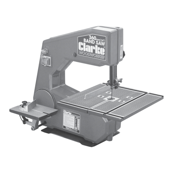
MAIN COMPONENTS Fig. 1 Power ON/OFF switch lock Blade tension bolt No volt switch Sanding table Drive wheel Blade tracking bolt Sanding disc Blade guard lock knob Motor pulley Work table Idler wheel Quadrant Lower blade guides Table lock knob Upper blade guides Sawdust extraction outlet Blade guard... -
Page 9: Assembly
ASSEMBLY Plan your installation. Ensure adequate floor space is available, with good lighting and ventilation, and an adequate electrical supply is close at hand. Your bandsaw is supplied fully assembled, except for the work and sanding tables. To assemble the work table to the bandsaw, proceed as follows: Fig. -
Page 10: Tips On Bandsaw Blades
MOTOR A ball bearing induction motor is fitted to the bandsaw, powerful enough for all your operating needs. SAWDUST EXTRACTION OUTLET It is not essential that this is used, however, if required it can be connected to a vacuum cleaner which will provide fast and efficient removal of sawdust from your machine. -
Page 11: Operation
OPERATION Fig. 6 Turn the key to ‘I’ “START”: Push the button marked with “1”. “STOP”: Push the button marked with “0” When the key is in the ‘O’ position, the machine will not operate. The key may be removed ONLY when in this position. -
Page 12: Changing Blades
Lower blade guide block CHANGING BLADES Turn the SWITCH TO ‘O’ and disconnect from the Fig. 8 power supply. Remove the key from the keyhole. Remove front cover (unscrew the two hex. socket head screws In both the upper and lower blade guide blocks, loosen the blade guide locking screws (A1 and B1) and move the guides away from the blade, similarly, loosen the lower support bearing locking... -
Page 13: Use Of Accessories
USE OF ACCESSORIES MITRE GUIDE Most crosscut work, especially with small pieces is more easily controlled with the use of a mitre guide The mitre guide is also essential for accurate mitre and compound mitre cuts. The guide is graduated to 45 for both left and right hand angles. -
Page 14: Power Disc Sanding
For best results in disk sanding, set the bandsaw at high speed. Replacement sandpaper discs are available from your CLARKE dealer (See CONSUMABLES on page 19). They can be obtained in three grit sizes and are self adhesive so that no glue is required to fix them to the aluminium disk. -
Page 15: Maintenance
MAINTENANCE BEFORE CARRYING OUT ANY SERVICING OR MAINTENANCE, DISCONNECT THE MACHINE FROM THE POWER SUPPLY CHANGING TYRES Eventually the rubber tyres on the bandsaw wheels will wear due to the constant contact of the sharp teeth of the blade. Lift the edge of the tyre with a small screwdriver and the tyre can be worked off the wheel easily. -
Page 16: Freehand Cutting
A large range of bandsaw blades, sanding belts and sanding discs is available for your Bandsaw to help you get maximum use from your machine. Consumables shown here are obtainable from your CLARKE Dealer. If you have any difficulty in obtaining them, please contact the CLARKE Customer Service Department. -
Page 17: Parts List & Diagrams
SPARE PARTS LIST Item Description Part No. Item Description Part No. Frame FM355001 Worktable FM355047 Wheel Support FM355002 FM355048 Axle Block FM355003 Quadrant FM355049 FM355004 Spring Supp’t Bush FM355050 Bolt FM355005 Spring FM355051 Washer FM355006 Lock Knob FM355052 FM355007 Pointer FM355053 Tension Spring FM355008... - Page 18 SPARE PARTS DIAGRAM...
- Page 19 MITRE GUIDE Item Description Part No. 92 Mitre Gauge FM355092 93 Pointer FM355093 94 Ruler Complete FM355094 95 Lock Knob FM355095 96 Screw FM355096 97 Washer FM355097 98 Washer FM355098 CIRCLE CUTTING ATTACHMENT Item Description Part No. 99 Clamp FM355099 100 Hex.
Need help?
Do you have a question about the CBS 355 and is the answer not in the manual?
Questions and answers