
Related Manuals for Clarke CBS250B


Summary of Contents for Clarke CBS250B
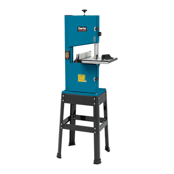
- Page 1 BAND SAW MODEL NO: CBS250B PART NO: 6460140 OPERATION & MAINTENANCE INSTRUCTIONS LS0718 - ISS 1 ORIGINAL INSTRUCTIONS...
-
Page 2: Environmental Protection
Before attempting to operate the machine, it is essential that you read this manual thoroughly and carefully follow all instructions given. GUARANTEE This CLARKE product is guaranteed against faulty manufacture for a period of 12 months from the date of purchase. Please keep your receipt as proof of purchase. -
Page 3: Safety Precautions
SAFETY PRECAUTIONS WARNING: WHEN USING ELECTRIC TOOLS BASIC SAFETY PRECAUTIONS SHOULD ALWAYS BE FOLLOWED TO REDUCE THE RISK OF FIRE, ELECTRIC SHOCK AND PERSONAL INJURY INCLUDING THE FOLLOWING. READ ALL THESE INSTRUCTIONS BEFORE ATTEMPTING TO OPERATE THIS PRODUCT AND SAVE THESE INSTRUCTIONS 1. - Page 4 • Wear protective hair covering to contain long hair. 9. Use protective equipment • Use safety glasses. • Use face or dust mask if working operations create dust 10. Connect dust extraction equipment • If the tool is provided with a connection for dust extraction and collecting equipment, ensure these are connected and properly used.
- Page 5 19. Stay alert • Watch what you are doing, use common sense and do not operate the tool when you are tired. 20. Check damaged parts • Before further use of tool, it should be carefully checked to determine that it will operate properly and perform its intended function. •...
-
Page 6: Safety Symbols
SAFETY SYMBOLS Read the manual Eye protection and safety should be worn instructions before Ear protection Dust mask should be should be worn worn HAZARD, Motor gets hot LIST OF CONTENTS. Main Box Band Saw (c/w fitted blade) Fixings Pack Table Table Insert (in Fixings Pack) Parallel Fence... -
Page 7: Electrical Connections
ELECTRICAL CONNECTIONS WARNING! Read these electrical safety instructions thoroughly before connecting the product to the mains supply. Before switching the product on, make sure that the voltage of your electricity supply is the same as that indicated on the rating plate. This product is designed to operate on 230VAC 50Hz. - Page 8 OVERVIEW Parts & Service: 020 8988 7400 / E-mail: Parts@clarkeinternational.com or Service@clarkeinternational.com...
-
Page 9: Assemble The Stand
ASSEMBLY ASSEMBLE THE STAND 1. On a flat level surface, assemble 2 sub assemblies as shown. • Parts required per assembly, 2 legs, 1 short beam, 1 short cross member and 8 short round head screws nuts and washers. • Do not tighten nuts fully at this stage. -
Page 10: Mount The Band Saw On To The Stand
MOUNT THE BAND SAW ON TO THE STAND WARNING: WHEN YOU MOUNT THE BAND SAW ON TO THE STAND WE RECOMMEND THAT YOU GET HELP BECAUSE OF THE WEIGHT OF THE BANDSAW. 1. Lift the band saw on to the stand. 2. -
Page 11: Connecting To A Dust Collector
3. Fit the table insert as shown. • Always replace the table insert when worn. FIT THE GUIDE RAIL TO THE TABLE 1. Loosely screw 4 bolts and washers into the bottom of the table as shown, 2. Slide the guide rail onto the shafts of the bolts 3. -
Page 12: Switching On/Off
FUNCTIONS SWITCHING ON/OFF 1. Press the green ON (I) button to start the band saw. 2. Press the red OFF (O) button to stop the band saw. NOTE: The blade may continue to rotate for a short time before coming to a complete stop. UPPER BLADE GUARD ADJUSTMENT 1. -
Page 13: Using The Push Stick
USING THE PUSH STICK • The push-stick serves as an extension of the operators hand as protection against accidentally touching the saw blade. • The push-stick should be used if the distance between the blade and rip fence is less than approx 150 mm. •... -
Page 14: Operation
OPERATION Before commencing work, ensure the work area is clean and tidy and the bandsaw table is clear of tools etc. Plan your work carefully and set the bandsaw up accordingly before switching on. 1. Check the blade is correctly tensioned before use (see page 17). 2. -
Page 15: Changing The Saw Blade
CHANGING THE SAW BLADE WARNING: DISCONNECT THE SAW FROM THE MAINS SUPPLY BEFORE CHANGING THE BLADE. REMOVING THE BLADE 1. Loosen the bolts shown and remove the guide rail. 2. Open the upper and lower doors. 3. Slide the lower blade guard to the left. -
Page 16: Fitting A Blade
FITTING A BLADE WARNING: BLADES ARE NORMALLY SUPPLIED COILED, TAKE CARE WHEN UNCOILING THE SAW BLADE AS THEY HAVE A TENDENCY TO SPRING OPEN. 1. Slide the blade over the wheels, NOTE: Turning the wheels as you do so makes this easier. •... -
Page 17: Adjusting The Blade Tension
ADJUSTING THE BLADE TENSION CAUTION: TOO MUCH TENSION CAN CAUSE THE SAW BLADE TO BREAK. TOO LITTLE TENSION CAN CAUSE THE BLADE TO MAKE IRREGULAR CUTS 1. Raise the upper blade guide fully. 2. Check the tension by pressing with a finger against the side of the blade, halfway between the table and upper guide. -
Page 18: Adjust The Guide/Thrust Bearings And Lower Blade Guides
2. Loosen the tracking control lock and manually rotate the upper wheel, taking care of the sharp blade 3. Turn the tracking control knob clockwise or anticlockwise until the saw blade tracks centrally on the rubber tyre. 4. After adjusting, retighten the tracking control lock and close the doors. -
Page 19: Maintenance And Servicing
MAINTENANCE AND SERVICING DAILY 1. Keep the machine clean. 2. Check the saw blade for missing teeth and cracks. 3. Open the top & bottom wheel covers and clean out all saw dust. WEEKLY 1. Open the top & bottom wheel covers and clean out all saw dust with a vacuum cleaner. -
Page 20: Parts Diagrams
PARTS DIAGRAMS Parts & Service: 020 8988 7400 / E-mail: Parts@clarkeinternational.com or Service@clarkeinternational.com... - Page 21 Parts & Service: 020 8988 7400 / E-mail: Parts@clarkeinternational.com or Service@clarkeinternational.com...
-
Page 22: Parts List
PARTS LIST 001 Slotted Insert 032 Hex head.thin Nut 002 Washer 033 Thread Bolt 003 Housing 034 Washer 004 Washer 035 Hex head bolt 005 Lower Door 036 Hex head bolt 006 Nut 037 Wing Knob 007 Latch Tab 038 Washer 008 Ext lock Washer 6 039 Washer 009 Hex head bolt M6x10... - Page 23 063 Indicator 087 Cross Pan Head Screw 064 Tension Knob 088 Rack 065 Hex head bolt 089 Guide Piece 066 Hex.nut 090 Adjusting Knob 067 Hex head bolt 091 Hex head lock nut 068 Rip Fence Extrusion 092 Cross Pan.hd.screw 069 Roll Pin 093 Lower Wheel 070 Lever...
-
Page 24: Specifications
SPECIFICATIONS Model CBS250B Power 370W, 230V Blade Speed 730 m/min Blade Length 1,712 mm Blade Width 10 mm Max Width of Cut 245 mm Max Depth of Cut 100 mm @ 90° / 75 mm @ 45° Table Size 333 x 336 mm... -
Page 25: Declaration Of Conformity
DECLARATION OF CONFORMITY Parts & Service: 020 8988 7400 / E-mail: Parts@clarkeinternational.com or Service@clarkeinternational.com... - Page 26 Parts & Service: 020 8988 7400 / E-mail: Parts@clarkeinternational.com or Service@clarkeinternational.com...
- Page 27 Parts & Service: 020 8988 7400 / E-mail: Parts@clarkeinternational.com or Service@clarkeinternational.com...
Need help?
Do you have a question about the CBS250B and is the answer not in the manual?
Questions and answers