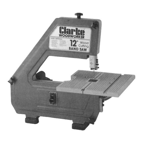
Summary of Contents for Clarke CBS-12WB
- Page 1 Clarke WOOD CUTTING 12" BANDSAW MODEL CBS-12WB PART NO. 6460008 OWNERS MANUAL BEFORE USI N G BE SURE TO REA D THIS MANUAL...
-
Page 2: Table Of Contents
CONTENTS UNPACKING AND CHECKING CONTENTS..... . TO KNOW YOUR BAND SAW ... ' ....Tension Adjustment Knob Cover Knobs Blade Guides... -
Page 3: Unpacking And Checking Contents
I. UNPACKING AND CHECKING CONTENTS M. TO KNOW YOUR BAND SAW Unpack carton, check your machine, to see parts listed below: 1. Tension adjusting knob . . . Tightening the knob (clockwise) will increase the tension on the blade. Loosening it (counter clockwise) will decrease the tension. (Tension lock knob must be released). -
Page 4: Assembly
ASSEMBLY Replacing The Blade Installing The Table Apply a coat of automobile wax to the table 1. Loosen the guide bar lock knob and position the upper guide assembly approximately one top and inside surfaces of trunnion that inch above the table and tighten lock knob. slide on frame. -
Page 5: Tensioning The Blade
Tensioning The Blade 7. Loosen the three (3) cover knobs by turning NOTE: Your bandsaw can use only 1/4" (6mm) wide blades, 56-1/8" (1425mm) long. A blade counterclockwise and remove cover. is included with this saw. Ensure that, the tension lock knob is tightened before turn on the NOTE: Replace the bandsaw cover after blade is machine. -
Page 6: Tracking The Blade
Tracking The Blade NOTE: W hen table is tilted to a bevel angle, the 1. Loosen the Tension Lock Knob (1/4 of a turn lower blade guide support should be lowered to counter-clockwise) turn tracking clear the table. After bevel cutting and returning adjustment set screw slightly with the hex table to zero position, always raise the lower blade wrench 3mm (Turning the set screw moves the... -
Page 7: Adjusting Upper Thrust Bearing
Adjusting Upper Thrust Bearing NOTE: After all adjustments have been made, turn the wheel by hand (clockwise) a few turns to 1. NOTE: The thrust bearing supports the blade check blade travel and clearance. (As diagram shown in paragram "Ten-sioning the blade") from the rear and will rotate when the blade Adjusting The Table is pushed against it while you are cutting. -
Page 8: Clamping Bandsaw To Workbench
IV. SAFETY RULES Follow instructions mounting General Safety Rules: workbench, substituting a board 18" x 24" 1. KEEP GUARDS IN PLACE and in working order. minimum size and using inch flat head screws, REMOVE ADJUSTING KEYS AND W RENCHES. Form habit of checking to lock washers, and hex nuts (not included). - Page 9 Special Safety Rules For Band Saws USE RECOMMENDED ACCESSORIES. Consult the owner's manual for 1. Place the blade guard to within approximately 1/8" above the material being cut. recommended accessories. The use of improper accessories may cause risk of injury 2.
-
Page 10: Grounding
VI. BASIC OPERATION & TROUBLE SHOOTING GUIDE V. GROUNDING Basic Operation GROUNDING INSTRUCTIONS A band saw is basically a "curve cutting" machine. It is also used for straight-line cutting operations such If an electrical problem occurs, earthing provides the path of least resistance for current cross cutting, ripping,... - Page 11 4. Trouble Shooting Guide Problem Probable Cause Solution Problem Probable Cause Solution 5 Guide bearings not adjusted 5 Adjust guide bearings to .002 Cuts properly. greater than max. thickness, Excessive Blade 1 Material loose in vise 1 Clamp work securely including weld, of the saw.
-
Page 12: Maintenance
VII. MAINTENANCE VIII TECHNICAL DAT A Lubricate the following components periodically. € Bench type, portable weight wood cutting band saw. 1. Ball bearings. € Motor direct drive, one speed operation. 2. Bearings of blade guides. € Table can be titled 0°— 45 ° for bevel cut. 3. -
Page 13: Parts Listing
IX. PARTS LISTING Ref. No. Description Part No. Unit Ref. No. Description Part No. Unit Knob MB6A-005 Shaft guide support MB6A-036 Washer * 1 7/64" x 47/64" x 1/16" Support upper guide MB6-014E Clamp-guide rod MB6-017 Support guide MB6-010E Screw set hex. * 1/4"... -
Page 14: Parts Diagram
Clarke POWER PRODUCTS DEAR CUSTOMER CONGRATULATIONS ON THE PURCHASE OF THIS CLARKE POWER PRODUCT WHICH WE TRUST WILL GIVE YOU LONG AND TROUBLEFREE SERVICE. SHOULD YOU EXPERIENCE ANY DIFFICULTY WITH THE ASSEMBLY OR OPERATION OF THIS PRODUCT, PLEASE CONTACT OUR SERVICE DEPARTMENT AT THE...


Need help?
Do you have a question about the CBS-12WB and is the answer not in the manual?
Questions and answers