Clarke Woodworker CBS250 Operating & Maintenance Instructions
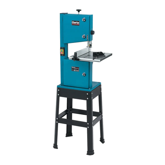
45 mm (10”) bandsaw & stand
Hide thumbs
Also See for Woodworker CBS250:

Related Manuals for Clarke Woodworker CBS250


Summary of Contents for Clarke Woodworker CBS250
- Page 1 245 MM (10”) BANDSAW & STAND 245 MM (10”) BANDSAW & STAND Part No. 6460200 MODEL No. CBS250 Part No. 6460135 OPERATING & MAINTENANCE INSTRUCTIONS GC0514...
-
Page 2: Table Of Contents
CONTENTS Specifications ................ 2 Guarantee ................3 Safety Precautions ..............4 Electrical Connections ............6 Unpacking The Machine ............. 7 Assembly ................8 Adjustments ................9 Changing Sawblade ............12 Operating Instructions ............12 Maintenance ..............14 Parts Diagrams ............... 15-16 Parts Lists ................. -
Page 3: Guarantee
Service@clarkeinternational.com Please note that the details and specifications contained herein are correct at the time of going to print. However CLARKE International reserve the right to change specifications at any time without prior notice. Always consult the machines data plate Do not dispose of this product with general household waste. -
Page 4: Safety Precautions
SAFETY PRECAUTIONS WARNING: As with all machinery, there are certain hazards involved with their operation and use. Exercising respect and caution will considerably lessen the risk of personal injury. However, if normal safety precautions are overlooked or ignored, personal injury to the operator or damage to property, may result. 1. - Page 5 DO NOT touch the blade immediately after use, when changing blade always allow time for it to cool. DO NOT use bent or cracked blades. (Replacement blades are available from your CLARKE dealer. Replace table insert if slot has become enlarged. When cutting wood, ensure all nails have been removed beforehand.
-
Page 6: Electrical Connections
ELECTRICAL CONNECTIONS This product is fitted with a standard 13 amp, 230 volt (50Hz), BS 1363 plug, for connection to a standard, domestic electrical supply. Should the plug need changing at any time, ensure that a plug of identical specification is used. WARNING ! THIS APPLIANCE MUST BE EARTHED This machine must be wired up in accordance with the following colour code: BLUE... -
Page 7: Unpacking The Machine
When lifting or moving this machine, it is strongly advised that assistance be used. Lay out all components carefully, and check against the list which follows to ensure all components are present. Should there be any material shortages, or damage suffered in transit, please contact your CLARKE dealer immediately. Check List Machine Body Fig.1... -
Page 8: Assembly
ASSEMBLY Stand (Refer to Fig.2) Assemble sub assy x 2, see fig. 3. Parts required per assy, 2 legs (L), 1 short beam (H), 1 short cross member (D), and 8 short round head screws nuts and washers. Do not tighten nuts at this stage. NOTE: Beams and cross members fit inside the legs. - Page 9 10. Fit the width of cut indicator to the front of the Fig.7 table using four bolts and washers supplied, ensure the cut-out is lined up with the ‘T’ slot in the table. DO NOT overtighten the bolts, the width of cut indicator must to be removed when changing or fitting new saw blades Width of cut...
- Page 10 Push the green ON button (see Fig 2 on page 7), and allow the saw blade to reach full speed before proceeding to feed the workpiece into the blade. Use both hands to feed the workpiece in to the blade. The work must be held flat on the table at all times to prevent binding of the blade.
-
Page 11: Adjustments
Mitre Cutting Fig.12 Most crosscut work, especially with small pieces is more easily controlled with the use of a mitre gauge The mitre gauge is also essential for accurate mitre and compound mitre cuts. The gauge is graduated to 60 for both left and right hand angles. - Page 12 Changing the Sawblade. Fig.13 Ensure the machine is switched OFF, and isolated from the mains electrical supply. • Remove the rip fence and bevel gauge - ‘A’. • Remove the width of cut indicator - ‘B’. • Remove the table insert - ‘C’. •...
- Page 13 Lower Blade Wheel Under normal circumstances, the bottom blade wheel does not need adjusting, it is factory set and should never alter. If however the blade tracks off centre and all the previous adjustments have been carried out correctly, proceed to ‘A’...
- Page 14 A. Upper Blade Guides Fig.17 Upper Blade Guides Slacken the grub screw ‘A’ Fig.17, and move the rear guide roller so that it comes into light contact, or to within 0.5mm of the back ‘D’ edge of the sawblade, as shown at ‘D’, Fig17.
-
Page 15: Parts Diagrams
PARTS DIAGRAM IMPORTANT: The use of parts other than CLARKE replacement parts may result in safety hazards, decreased tool performance and may invalidate your warranty. - Page 16 PARTS DIAGRAM PARTS & SERVICE TEL: 020 8988 7400 e-mail as follows: PARTS: Parts@clarkeinternational.com SERVICE: Service@clarkeinternational.com...
-
Page 17: Parts Lists
PARTS LIST Item Part No Description QD250001 Slotted Insert QD250002 Washer QD250003 Housing QD250004 Washer QD250005 Door-Lower QD250006 Housing + Nut QD250007 Tongue QD250008 Ext. LockWasher 6 QD250009 Hex. Hd.Bolt M6x10 QD250010 Door-Upper QD250011 Saw Blade QD250012 Retaining Ring QD250013 Ball Bearing QD250014 Upper Wheel... - Page 18 PARTS LIST Item Part No Description QD250041 Hex.Hd Flange Nut QD250042 Spacer Bushing QD250043 Bush QD250044 Square Neck Bolt QD250045 Cross Pan Hd. Screw QD250046 Hex.Hd. Lock Nut QD250047 Blade Guard QD250048 Square Neck Bolt QD250049 Trunnion Lower QD250050 Washer QD250051 Int.Hd.Screw QD250052...
- Page 19 QD250104 Motor QD250105 Plate Mounting Motor QD250106 Spring Washer QD250107 Bearing Bolt Upper QD250108 Hex.Hd Bolt QD250109 Stepped Pin IMPORTANT: The use of parts other than CLARKE replacement parts may create safety hazards, decreased performance, and may invalidate your warranty.
Need help?
Do you have a question about the Woodworker CBS250 and is the answer not in the manual?
Questions and answers