
Subscribe to Our Youtube Channel
Related Manuals for Eaton VICKERS SystemStak


Summary of Contents for Eaton VICKERS SystemStak
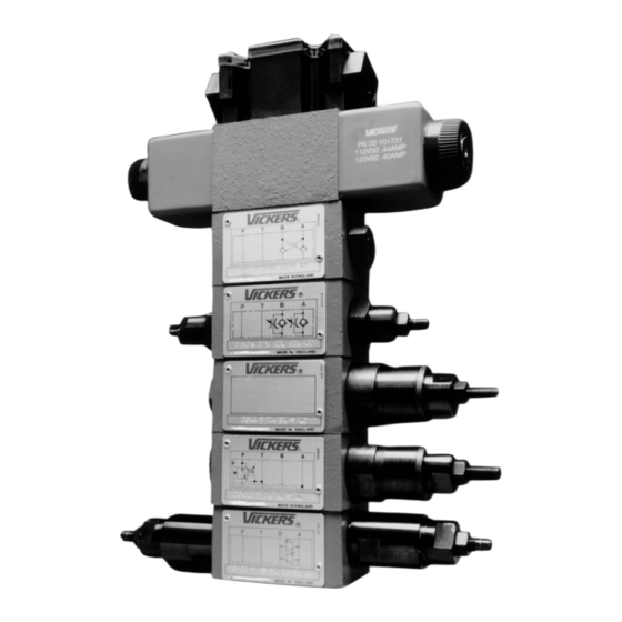
- Page 1 ® VICKERS ® SystemStak Valves ISO 4401-03; NFPA-D03; 315 bar (4500 psi); 60 L/min (15.7 USgpm) GB 2027B...
- Page 2 Build a Compact, Cost-Effective, Reliable Hydraulic System with Vickers SystemStakt Valves Reduces System Space SystemStak Systems... Easy to Requirements Understand, Easy to Design SystemStak valves make compact SystemStak circuitry is best shown hydraulic systems in which specific using slightly different symbols than function valves are “sandwich”...
- Page 3 SystemStak Systems . . . Easy to Understand, Easy to Design Figure 6 Fig. 7 represents a complete SystemStak system, showing typical use of functions available from this range. The circuit diagram also shows the use of a tapping plate for accessing line pressure readings, and a blanking plate to close off an unused station of a multi-station manifold.
- Page 4 Table of Contents Function Basic symbol Basic model Features Page Relief DGMC Single, dual and crossport models Counterbalance DGMR Control in port T Sequence DGMR1 Single port P sequence Reducing/relieving DGMX Piloted from (and reduced pressure in) port P, A or B Direct check DGMDC Single check in any port;...
- Page 5 Relief Valves DGMC-3-4* DGMC2-3-4* General Description Typical Section These two-stage adjustable pressure relief valves limit the maximum pressure in the line(s) controlled by the integral relief valve elements. Pressure adjustment options of control knob (with or without keylock) or screw/locknut design are available. The two-stage operation is basically identical to long-established balanced piston valves, described in detail in Vickers...
- Page 6 Relief Valves DGMC-3-4* DGMC2-3-4* Performance Second function Second line of dual models Characteristics Code Pressure Discharge Usage Pressure override limited in into Typical performance for PT models at max. pressure settings with mineral oil at Dual with 21 cSt (102 SUS) and at 50_C (122_F). Dual with 5000 Omit for single line models...
- Page 7 Installation Dimensions in mm (inches) DGMC(2)-3**-**(-B*-**)-4* Models with type W adjuster To adjust valve setting slacken off locknut and turn adjuster screw . Turn clockwise to increase pressure; counter-clockwise to decrease pressure Re-tighten locknut after completing adjustment. A max. 79 (3.1) fully out Line A adjustment Line B or line P adjustment...
- Page 8 Installation Dimensions in mm (inches) E max. Line A adjustment Line B adjustment 16,75 (0.66) 16,75 (0.66) 8 (0.13) max. 10 (0.4) max. F max. G max. Model DGMC-3-AB-*W-4* – – 164 (6.5) DGMC-3-BA-*W-*-4* – 164 (6.5) – DGMC2-3-AB-*W-BA-*W-4* 234 (9.2) –...
- Page 9 Pressure Controls: Counterbalance, Sequence and Pressure Reducing Valves DGMR(1)-3-4* DGMX*-3-4* Typical Section General Description These single-stage valves operate by the application of pressure on the end of the valve spool, acting against a spring which is loaded by means of the adjustment mechanism.
- Page 10 Model Code for Counterbalance, Sequence and Pressure Reducing Valves DGM *(*) -3- ** (*) - * - Type Gage port R = Counterbalance function B = G BSPF) I-20 UNF-2B) R1 = Sequence function S = SAE 4 ( X1 = Pressure reducing, underlapped X2 = Pressure reducing, overlapped Design number, 40 series X3 = Pressure reducing, overlapped,...
- Page 11 Performance Characteristics Typical performance with mineral oil at 21 cSt (102 SUS) and at 50_C (122_F). DGMX*-3-P* DGMR1-3-PP DGMX3-3 DGMX2-3 DGMX1-3 4000 4000 3000 3000 2000 2000 1000 1000 L/min L/min 16 USgpm 16 USgpm Flow rate Reverse flow to T line Reduced pressure line Flow rate DGMX*-3-P*...
- Page 12 Installation Dimensions in mm (inches) DGMR-3-TA-**-*-4* DGMR1-3-PP-**-*-4* DGMX(*)-3-P*(L)-**-*-4* Models with type W adjuster To adjust valve setting slacken off locknut and turn adjuster screw Turn clockwise to increase pressure; counter-clockwise to decrease pressure. Re-tighten locknut after completing adjustment. DGMX2-3-**L models have adjuster and end cap/gage port locations interchanged from positions shown.
- Page 13 Direct Check Valves DGMDC-3-4* Typical Section General Description These valves allow free flow in one direction in the line in which the check valve element(s) is (are) located; flow in the opposite direction is not possible. Functional Symbols DGMDC-3-X-A* Model Code for Direct Check Valves DGMDC-3- * - * * (- * * )- 4*...
- Page 14 Performance Characteristics Typical performance with mineral oil at 21 cSt (102 SUS) and at 50_C(122_F) Pressure drop: free flow through check valve L/min 16 USgpm Flow rate For other viscosities, see “Further Information”. Internal Leakage Across Closed Check Valve Less than 0,25 ml/min (0.015 in /min) at 250 bar (3625 psi)
- Page 15 Installation Dimensions in mm (inches) DGMDC-3-Y-A*-B*-4* DGMDC-3-X-A*-4* DGMDC-3-X-T*-4* DGMDC-3-Y-A*-4* DGMDC-3-Y-P*-4* 101 (4) max. (0.51) (1.57) Ø3 (0.12 dia) 3,5 (0.14) (0.47) 88 (3.46) max. DGMDC-3-X-B*-4* DGMDC-3-Y-B*-4* 4 off “O” seals supplied for this mounting face 4 holes through: Ø5,3 (0.21 dia) 47,6 (1.87) (1.8)
- Page 16 Pilot Operated Check Valves DGMPC-3-4* Typical Section General Description These valves provide pilot operated check functions in one or both service lines (A or B), the operating pilot supply coming from the opposite service line. Thus with pressure in one service line the check valve in the other service line will be open (subject to system/actuator pressures being correct for the valve...
- Page 17 Performance Characteristics Pressure Drop Data Typical performance with mineral oil at 21 cSt (102 SUS) and at 50_C(122_F) u Pressure drop: flow path A1 to A or B1 to B (no pilot-pressure Pressure drop: flow path A to A1, or B to B1 with check valve operation) pilot-operated fully open L/min...
- Page 18 Installation Dimensions in mm (inches) DGMPC-3-(D)AB*-(D)BA*-4* DGMPC-3-(D)AB*-4* 101 (4) max. (0.51) (1.57) (0.9) Ø3 (0.12 dia) 12 (0.47) 3,5 (0.14) 97 (3.82) DGMPC-3-(D)BA*-4* 4 off “O” seals supplied for this mounting face 4 holes through: Ø5,3 (0.21 dia) B(B1) 47,6 (1.87) (1.8) A(A1)
- Page 19 Flow Restrictor Valves DGMFN-3-4* Typical Section General Description These valves regulate flow by means of an adjustable orifice which is not pressure compensated, and flow through the valve is entirely dependent upon pressure drop at any particular setting of the orifice. Dual service-line models with an integral non-return valve around each control orifice provide for meter-in or meter-out...
- Page 20 Performance Characteristics Pressure Drop Typical performance with mineral oil at 21 cSt (102 SUS) and at 50_C(122_F) Type “1” needle (see model codes Type “2” needle (see model codes Number of turns of adjuster Number of turns of adjuster L/min L/min 16 USgpm 16 USgpm...
- Page 21 Installation Dimensions in mm (inches) DGMFN-3-X-***(-***)-4* DGMFN-3-Y-***(-***)-4* DGMFN-3-Z-***-4* Models with type W adjuster To adjust valve setting, slacken off locknut and turn screw . Re-tighten locknut after completing adjustment. Line A or line T adjustment Line B or line P adjustment (according to model type) (according to model type) ) A/F hex.
- Page 22 Recommendations on filtration methods B = Height of intermediate valve stack, comprising ensure that viscosities stay within those Vickers SystemStak valve(s) plus tapping and the selection of products to control specified under “Hydraulic Fluids”. plates, etc.
- Page 23 Further Information Pressure Drop at Other Viscosities Published pressure drop data is valid for a fluid viscosity of 21 cSt (102 SUS). The graph shows the approximate percentage change in pressure drop for a range of other viscosities. To determine the approximate pressure drop for any given fluid viscosity, multiply the published data by the % factor for the required viscosity.
- Page 24 Vickers ® DG4V-3 flows DG4V-3S flows ISO 4401, to 80 l/min to 40 l/min size 03; ANSI/ Solenoid Operated Directional Valves (21 USgpm), (10.5 USgpm), B93.7M-D03 Catalog 6* design 6* design...
-
Page 25: Table Of Contents
Table of Contents Introduction Features and Benefits Characteristics Functional Symbols Model Code Operating Data Performance Data Installation Dimensions DG4V-3-*A(L)-(V)M-S6-U-**-60 DG4V-3-*A(L)-(Z)-(V)M-S3-FPA5W-*2-60 DG4V-3-*A(L)-(Z)-(V)M-S4-FPA5W-*2-60 DG4V-3-*A(L)-(Z)-(V)M-S5-F-*2-60 Electrical Plugs and Connectors Subplates, Connection Plates and Mounting Surfaces DGMA-3-B-1* Blanking Plate DGMA-3-C2-11 Crossover Plate DGMA-3-T*-1*-* Tapping Plate DGAM-3-01-1*-R (Metric bolt tapping) DGAM-3-01-1* (UNC bolt tapping) Adaptor plate, Size 05 to 03 for pressure up to 210 bar (3000 psi) DGVM-3-1*-*, DGMS-3-1E(Y)-1*-* Single station subplate, rear and side tapped port... -
Page 26: Introduction
4000 4000 3000 3000 2000 2000 1450 1450 Flow rate (l/min) Flow rate (l/min) DG4V-3S DG4V-3S DG4V-3 DG4V-3 Typical maximum pressure differential (P-A-B-T) flow en- velope, blocked center spool. Eaton Vickers Solenoid Operated Directional Valves Product Catalog V-VLDI-MC011-E September 2008... -
Page 27: Features And Benefits
Three coil options are available: ISO4400 (DIN 43650) D1 – Encapsulated diode coil shown (Industrial application) D2 – Encapsulated diode (Mobile application) D7 – Transzorb type Eaton Vickers Solenoid Operated Directional Valves Product Catalog V-VLDI-MC011-E September 2008... -
Page 28: Characteristics
Eaton rep- ture range, ensure that vis- resentative where limits are cosities stay within the limits outside those for mineral oil. specified in the “Hydraulic fluids” section. Eaton Vickers Solenoid Operated Directional Valves Product Catalog V-VLDI-MC011-E September 2008... -
Page 29: Functional Symbols
Port B spring centered Port T • For differences in valve func- tion, refer to Performance Data page 11. Sol. A Sol. B F build spools. ◊ Transient condition only Eaton Vickers Solenoid Operated Directional Valves Product Catalog V-VLDI-MC011-E September 2008... -
Page 30: Model Code
(includes “H” feature seal) Z – No overrides at either end No override in non-solenoid end of single solenoid valves Not available on DG4V-3S, AC models Eaton Vickers Solenoid Operated Directional Valves Product Catalog V-VLDI-MC011-E September 2008... - Page 31 7 – 207 bar (3000 psi) for DC fitted high performance models, DG4V-3, including spool position indicator type S6. Design number 60 – Basic design 61 – Type 8 spool Eaton Vickers Solenoid Operated Directional Valves Product Catalog V-VLDI-MC011-E September 2008...
-
Page 32: Operating Data
For applications where valves are to remain pressurized (either energized or de-energized) at pressures over 210 bar (3045 psi) without frequent switching, it is recommended to use the high performance model, DG4V-3. 1st half cycle; armature fully retracted. Eaton Vickers Solenoid Operated Directional Valves Product Catalog V-VLDI-MC011-E September 2008... - Page 33 Difficult environments could mean that extra screening may be necessary to avoid the interference. Micro-switch type “S3”, “S4” and “S5” Voltage 250V maximum 50/60 Hz Maximum current Eaton Vickers Solenoid Operated Directional Valves Product Catalog V-VLDI-MC011-E September 2008...
-
Page 34: Performance Data
521B & 561B USgpm Consult Eaton regarding each application that will jointly have Flow rate flow rates approaching this curve and a pressurized volume exceeding 2000 cm (122 cu.in.) Eaton Vickers Solenoid Operated Directional Valves Product Catalog V-VLDI-MC011-E September 2008... - Page 35 (a) Single flow path, i.e. P to (coil designations *L in model T is drained at all times. A, P to B, A to T or B to T. code) the maximum flow is Eaton Vickers Solenoid Operated Directional Valves Product Catalog V-VLDI-MC011-E September 2008...
- Page 36 – – – Energized – – 521B 6∆ – – – 561B De-energized – – 11∆ – Energized 6∆ – – – “B” plugged ∆ “A” plugged m“P” plugged Eaton Vickers Solenoid Operated Directional Valves Product Catalog V-VLDI-MC011-E September 2008...
-
Page 37: Installation Dimensions
AC solenoid coils will burn out under this improper usage. 2. “Y” feature is field-convertible from “H” type manual override (omitting spacer), but is not field-convertible from other models. Eaton Vickers Solenoid Operated Directional Valves Product Catalog V-VLDI-MC011-E September 2008... - Page 38 Codes “FJ” and “FW”: 2 lead wires for each solenoid, approximately 150,00 (6.00) long. M3 (#6) terminals provided for customer connection. Codes “FTJ” and “FTW”: Valve supplied with lead wires connected into terminal strip suitable for M3 (#6) terminals for customer connection. Eaton Vickers Solenoid Operated Directional Valves Product Catalog V-VLDI-MC011-E September 2008...
-
Page 39: Dg4V-3-*A(L)-(V)M-S6
* = P , T, A or B, as required iron: 7 ,0 (0.3) P10-A10 hhOrder in multiples of 25 (1.0 mm dia orifice in ports For gray iron: 6,5 (0.25) per part number P and A) Eaton Vickers Solenoid Operated Directional Valves Product Catalog V-VLDI-MC011-E September 2008... -
Page 40: Electrical Plugs And Connectors
Port A Port A Port B The conduit box dimensions used for the PA/PBW type connector are different from those on the other “F” type coil models. Dimensions in mm(in). Eaton Vickers Solenoid Operated Directional Valves Product Catalog V-VLDI-MC011-E September 2008... - Page 41 3 – green lead (ground) 3 – green lead (ground) monitor switch, 2 – lead to monitor switch, 2 – lead to monitor switch, 2 – lead to monitor switch, common common common Eaton Vickers Solenoid Operated Directional Valves Product Catalog V-VLDI-MC011-E September 2008...
- Page 42 • Works only with DC voltage CETOP 3 • Polarity dependent Do Diode Diode Alone Diode/Zener Coil Coil CETOP 5 Do Diode Diode Alone Diode/Zener (No 2) (No 2) (No 1) (No 1) Eaton Vickers Solenoid Operated Directional Valves Product Catalog V-VLDI-MC011-E September 2008...
-
Page 43: Subplates, Connection Plates And Mounting Surfaces
(or “B”) suffix – ISO 228 (BSPF) ports and/or metric attaching bolt tappings. “S” suffix – SAE/UNC the mounting faces. ports and/or UNC attaching bolt tappings. Eaton Vickers Solenoid Operated Directional Valves Product Catalog V-VLDI-MC011-E September 2008... -
Page 44: Dgma-3-B-1* Blanking Plate
(for 1/4” O.D. tubing) 48,4 (1.9) 46,0 (1.8) Nameplate 75,0 (3.0) 4 holes Ø 5,6 (0.22 dia.) 20,0 DGMA-2-T1-1*–* DGMA-2-T2-1*–* (0.78) (Ports A and B) (Ports P and T) Dimensions in mm(in). Eaton Vickers Solenoid Operated Directional Valves Product Catalog V-VLDI-MC011-E September 2008... -
Page 45: Dgam-3-01-1*-R (Metric Bolt Tapping) Dgam-3-01-1* (Unc Bolt Tapping)
35,0 57,25 84,0 (1.38) (2.25) (3.31) 72,0 (2.83) 12,75 (0.5) 20,0 36,00 (.787) 35,0 (1.42) (1.37) 59,25 (2.33) 4 ports .750-16 UNF-2B for side ports. Dimensions in mm(in). Eaton Vickers Solenoid Operated Directional Valves Product Catalog V-VLDI-MC011-E September 2008... -
Page 46: Dgvm-3-1*-*, Dgms-3-1E(Y)-1*-* Single Station Subplate, Rear And Side Tapped Port
Side 12,0 (0.47) deep DGVM–3–1*–S Rear 3/4” 16 UNF–2B x 14,3 DGMS–3–1E–1–S* Side (0.56) deep (SAE) DGMS–3–1EY–1–S* Side 5/8” 18 UNF–2B x 12,7 (0.5) deep (SAE) Dimensions in mm(in). Eaton Vickers Solenoid Operated Directional Valves Product Catalog V-VLDI-MC011-E September 2008... -
Page 47: Dgms-3-3E-1*-* Multi-Station Subplate
208 (8.19) DGMS–3–5E–1*–* 271 (10.7) 258 (10.15) DGMS–3–6E–1*–* 321 (12.7) 308 (12.12) u Thru connection P and T ports on types DGMS-3-2EX-1*-* and DGMS-3-3EX-1*-* Dimensions in mm(in). Dimensions in mm(in). Eaton Vickers Solenoid Operated Directional Valves Product Catalog V-VLDI-MC011-E September 2008... -
Page 48: Mounting Surface
Vickers size 3 valves this in mm. Inch conversions diameter may be increased to are accurate to 0.01" unless Ø7,5 (0.29 dia). stated. #10-24 UNC-2B optional Dimensions in mm(in). Eaton Vickers Solenoid Operated Directional Valves Product Catalog V-VLDI-MC011-E September 2008... -
Page 49: Appendix
Do thread engagement in the not over tighten hold-down subplate/manifold block. bolts beyond recommended Bolts should be torqued to values. 5–7 N.m (44–62 lbf. in.) with Eaton Vickers Solenoid Operated Directional Valves Product Catalog V-VLDI-MC011-E September 2008... -
Page 50: Spare Parts Data
“F” noid is not held energized. DG4V-3S (AC) coils coils Single sol. valve 1,5 (3.3) (3.5) Double sol. valve (4.0) (4.4) Single sol. valve w/ position (4.4) (4.4) switch Eaton Vickers Solenoid Operated Directional Valves Product Catalog V-VLDI-MC011-E September 2008... -
Page 51: Temperature Limits
18/16/13 Axial piston motors 19/17/14 18/16/13 17/15/12 Ordering Procedure When placing an order, please specify full model designations of valves, subplates and kits. Refer to relevant “Model Code” sections. Eaton Vickers Solenoid Operated Directional Valves Product Catalog V-VLDI-MC011-E September 2008... - Page 52 This page left intentionally blank.
- Page 53 This page left intentionally blank.
- Page 54 This page left intentionally blank.
- Page 55 Tel: 952-937-9800 Fax: 952-294-7722 www.eaton.com/hydraulics Eaton Hydraulics Operations Asia Pacific Eaton © 2008 Eaton Corporation Hydraulics Operations Europe 11th Floor Hong Kong New World Tower All Rights Reserved Route de la Longeraie 7 300 Huaihai Zhong Road Printed in USA...
Need help?
Do you have a question about the VICKERS SystemStak and is the answer not in the manual?
Questions and answers