
Related Manuals for Siemens SITRANS FUE1010 IP65 NEMA 4X


Summary of Contents for Siemens SITRANS FUE1010 IP65 NEMA 4X
- Page 1 SITRANS F Ultrasonic Flowmeters SITRANS FUE1010 IP65 NEMA 4X - 7ME3500 Operating Instructions Edition 12/2014 Answers for industry.
- Page 3 Introduction Safety notes Description SITRANS F Installing/mounting Ultrasonic Flowmeters FUE1010 IP65 NEMA 4X Connecting Commissioning Operating Instructions Functions Alarm, error, and system messages Service and maintenance Troubleshooting Technical data Appendix Appendix 12/2014 A5E03086491-AC...
- Page 4 Note the following: WARNING Siemens products may only be used for the applications described in the catalog and in the relevant technical documentation. If products and components from other manufacturers are used, these must be recommended or approved by Siemens. Proper transport, storage, installation, assembly, commissioning, operation and maintenance are required to ensure that the products operate safely and without any problems.
-
Page 5: Table Of Contents
Table of contents Introduction ............................. 9 Preface ............................9 Items supplied ........................... 9 History ............................. 10 Further Information ......................... 10 Safety notes ............................11 General safety instructions ..................... 11 Warning Symbols ........................12 Laws and directives ........................ 13 Lithium batteries ........................14 Installation in hazardous area .................... - Page 6 Table of contents 5.5.2 Sensor Identification and Selection..................59 5.5.3 Reflect Mount ......................... 62 5.5.4 Direct Mount ........................... 65 5.5.5 1012T Mounting Tracks ......................70 5.5.6 Zero Flow Adjust Menu ......................79 Mounting Temperature Sensors .................... 83 Sensor Wiring ......................... 86 Commissioning .............................
- Page 7 Table of contents Technical data ............................ 171 11.1 Technical Data ........................171 Appendix............................. 173 Certificates ..........................173 Ordering ..........................173 I/O Connections and Wiring ....................173 RS-232 Connection ....................... 194 Flowrate Calibration and Calibration Tables ................. 205 Appendix............................. 209 Installation/Outline Drawings ....................209 Glossary .............................
- Page 8 Table of contents Table 11- 1 Performance Specifications ....................... 171 Table A- 1 Connection Diagrams and Part Numbers .................. 173 Table A- 2 Input/Output Wiring (TB2) - 7ME39400AL00 and 7ME39400AL01 I/O Module (for 7ME3500 or 7ME3530 only) ...................... 175 Table A- 3 Input/Output Wiring (TB3) - 7ME39400AL00 and 7ME39400AL01 I/O Module ......
- Page 9 Table of contents Figure 5-5 KeyPad ............................48 Figure 5-6 Typical Installation Menu Screen ....................49 Figure 5-7 Reflect Mount (Pipe shown from above in 12 o'clock position) ........... 56 Figure 5-8 Direct Mount (Pipe shown from above in 12 o'clock position) ............. 57 Figure 5-9 Sensor Alignment (Horizontal Plane) ...................
- Page 10 Table of contents Figure A-4 7ME39404SB00 Analog Input Module ..................189 Figure A-5 Temperature Sensor Inputs ....................... 191 Figure A-6 7ME39400SA00 - Analog Input Module ..................192 Figure A-7 1015CPC-N Serial Interface Cable .................... 195 FUE1010 IP65 NEMA 4X Operating Instructions, 12/2014, A5E03086491-AC...
-
Page 11: Introduction
Introduction Preface These instructions contain all the information you need for using the device. The instructions are aimed at persons mechanically installing the device, connecting it electronically, configuring the parameters and commissioning it as well as service and maintenance engineers. Note It is the responsibility of the customer that the instructions and directions provided in the manual are read, understood and followed by the relevant personnel before installing the... -
Page 12: History
The Operating Instructions are available on the CD-ROM shipped with the device and on the Internet on the Siemens homepage, where further information on the range of SITRANS F flow meters may also be found: Product information on SITRANS F in the Internet (http://www.siemens.com/sitransf) -
Page 13: Safety Notes
Safety notes General safety instructions CAUTION Correct, reliable operation of the product requires proper transport, storage, positioning and assembly as well as careful operation and maintenance. Only qualified personnel should install or operate this instrument. Note Alterations to the product, including opening or improper repairs of the product, are not permitted. -
Page 14: Warning Symbols
Safety notes 2.2 Warning Symbols Warning Symbols Symbol Explanation Consult operating instructions Hot surface Dangerous electrical voltage Corrosive materials Toxic materials Isolate the device from power using a circuit-breaker Protect the device from impact otherwise loss of degree of protection Protective insulation;... -
Page 15: Laws And Directives
Operating Instructions must be observed. NOTICE Material compatibility Siemens can provide assistance with the selection of sensor parts. However, the full responsibility for the selection rests with the customer and Siemens can take no responsibility for any failure due to material incompatibility. -
Page 16: Lithium Batteries
Safety notes 2.4 Lithium batteries Lithium batteries Lithium batteries are primary power sources with high energy content designed to represent the highest possible degree of safety. WARNING Potential hazard Lithium batteries may present a potential hazard if they are abused electrically or mechanically. - Page 17 Intrinsically safe data WARNING Explosion Hazard User must install unit with Siemens drawings. With intrinsically safe circuits, use only certified meters appropriate for the transmitter. If a non-conforming supply unit is used, the "fail-safe" type of protection will no longer be effective and the approval certification will be invalid.
- Page 18 Safety notes 2.5 Installation in hazardous area ● Sensor and transmitter are connected to the potential equalization. For intrinsically safe output circuits potential equalization must be maintained along the entire connection path. ● When protective earth (PE) is connected, no potential difference between the protective earth (PE) and the potential equalization (PA) can exist, even during a fault condition.
-
Page 19: Safety Notes
Safety notes 2.6 Safety Notes Safety Notes Safety Information for Hazardous Areas DANGER Explosion Hazard Will Cause Death, Serious Injury or Property Damage. Restrict use and repair to qualified personnel. DANGER Explosion Hazard Death or severe personal injury and/or equipment and property damage will result if proper Hazardous (Classified) Locations installation precautions are not taken. - Page 20 The sales contract contains the entire obligation of Siemens. The warranty contained in the contact between the parties is the sole warranty of Siemens. Any statements contained herein do not create new warranties or modify the existing warranty.
- Page 21 Safety notes 2.6 Safety Notes Transmitter ● Intrinsically safe connections Class I and II, Division 1, Groups A, B, C, D, E, F and G; ● Nonincendive for Class I, Division 2, Groups A, B, C and D; ● Suitable for Class II, Division 2, Groups E, F and G outdoor (Type 4X), Class III (CSA only) ●...
- Page 22 Safety notes 2.6 Safety Notes Safety Information for Hazardous Areas Note Ratings under this heading apply to specific model families. Check Your Model Number: FUE1010, 7ME3500 FM-CSA installation Read, understand and follow all safety instruction on the electronic media provided. This equipment is rated for use in hazardous (classified) locations as stated below and must be installed according to the 1010-443 installation drawing provided on the media.
- Page 23 Safety notes 2.6 Safety Notes Transmitter Markings and Explanations ● II (1) G [Ex ia] IIC– Transmitter located in the non-hazardous area with intrinsically safe circuits of category Ex ia, which can be connected to Category 1 Sensors for use in potentially explosive atmosphere containing gases ●...
- Page 24 Safety notes 2.6 Safety Notes FUE1010 IP65 NEMA 4X Operating Instructions, 12/2014, A5E03086491-AC...
-
Page 25: Description
NEMA 4X Energy Transmitter SITRANS FUE1010 Transmitters The SITRANS FUE1010 IP65 NEMA 4X series transmitters are available in Dual Channel and Dual Path versions. The transmitters include a graphic display providing flow rate, diagnostics data and keypad interface to access on-screen software setup menus. Safety agency approved SITRANS FUE1010 series transmitters have hazardous area certification as indicated in the label examples below. -
Page 26: Applications
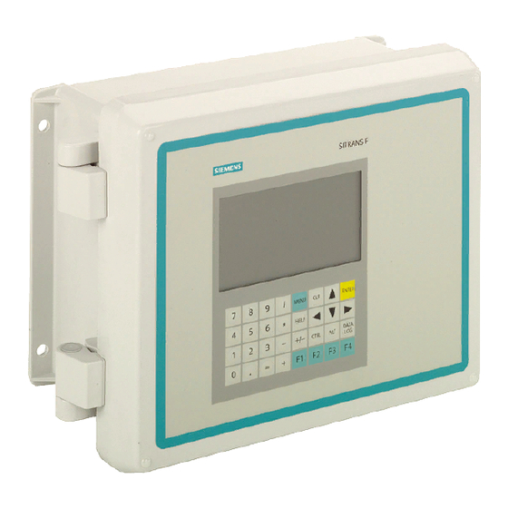
Figure 3-1 Typical Transmitter Label SITRANS FUE1010 Model Numbers The SITRANS FUE1010 IP65 NEMA 4X model number: ● 2 Channel / 2 Path - 7ME3500-2 Figure 3-2 NEMA 4X Transmitter Case... -
Page 27: Theory Of Operation
Description 3.4 Theory of Operation Typical Applications The typical applications of the flow meter for heat energy flow include: ● Chilled water ● Hot water ● Condenser water ● Lake source cooling ● Thermal storage ● Chemical feed flow Typical Industries Serviced ●... - Page 28 Description 3.4 Theory of Operation ① Velocity of Sound ② Flow Vector ③ Pipe ID ④ Wide Beam Sensors ∅= sin (VOS / V Where: VOS = Velocity of sound in liquid phase = Phase velocity of sensor phase = 2 * ID / (VOS * cos ∅) ID = Pipe inside diameter = Transit time in liquid * DT / (2 * TL)
- Page 29 Description 3.4 Theory of Operation ① Fluid velocity near the axis of the flow stream tends to be greater. The Reynolds number is then computed as follows: where: viscosity = cS = cP/density Pipe ID = inches = inches/sec cS = kinematic viscosity cP = absolute viscosity The flow meter then uses this computation of Reynolds number to compensate the raw flow velocity for conditions of laminar or turbulent flow profile as defined by an internal Reynolds...
- Page 30 Description 3.4 Theory of Operation 2-Channel Dual Channel provides two independent measurement channels that operate simultaneously. Depending on the specific model, Dual Channel supports: Clamp-on Transit- time, In-line Transit-time and Reflexor. ① ⑤ Upstream Sensors Pipe B Output Flow ② ⑥...
- Page 31 Description 3.4 Theory of Operation Channel 1+2 and Channel 1-2 Arithmetic operation produces data output via a virtual Channel 3, proportional to the sum or difference of the liquid and energy flow of two independent pipes. This requires setting the two channels to operate independently.
- Page 32 Description 3.4 Theory of Operation Flow Calibration Factor Normally, the flow stream is parallel to the axis of the pipe. On this basis, the calibration factor of a clamp-on ultrasonic flow meter is proportional to the cosine of the beam angle relative to the pipe axis.
-
Page 33: Installing/Mounting
Installing/mounting Installation safety precautions WARNING In applications with working pressures/media that can be dangerous to people, surroundings, equipment or others in case of pipe fracture, we recommend that special precautions such as special placement, shielding or installation of a security guard or a security valve are taken when the sensor is mounted. -
Page 34: Use According To Specifications
● Use the sensors as a footboard for installation purposes. ● Change the flow meter in any way. For e.g. decomposition of material in connection with processing, welding and use of accessories and spare parts not approved by Siemens. Note If the flowmeter is not used according to the specifications, the manufacturer cannot be held responsible for any resulting damage. -
Page 35: Mounting The Transmitter
Installing/mounting 4.5 Mounting the Transmitter ● Avoid mounting on or near weld seams. ● Pipe must be full to achieve proper operation. Mounting the Transmitter WARNING Hazardous Voltage May cause death or serious personal injury. Disconnect power before working on this product. Wall Mounting The transmitter can be mounted on any wall surface including wood, metal or concrete. - Page 36 Installing/mounting 4.5 Mounting the Transmitter ① ④ 2-in (6cm) pipe Cable Entry Ports ② ⑤ Transmitter Mounting Flange (also use for wall mounting) ③ ⑥ Mounting Plate U-Bolt Assembly for standard 2-in (6 cm) mounting pipe Figure 4-1 Pipe Mounting and Mounting Locations for Transmitter Note Use conduit fittings or cable glands on all cables.
-
Page 37: Connecting
Connecting Safety notes for connecting Use in hazardous locations DANGER Explosion Hazard Death or severe personal injury and/or equipment and property damage will result if proper Hazardous (Classified) Locations installation precautions are not taken. Restrict use and repair to qualified personnel. Only qualified personnel may carry out work on the electrical connections. - Page 38 Connecting 5.1 Safety notes for connecting DANGER Explosion Hazard "Flameproof enclosure" type of protection Only open devices with type of protection "Flameproof enclosure" (e.g. FUT1010 NEMA 7) in hazardous areas when the power to the device is turned off, otherwise there is a risk of explosion.
- Page 39 Connecting 5.1 Safety notes for connecting DANGER Explosion Hazard Devices with the common approval "Intrinsically safe" and "Flameproof" The following is applicable for devices with the common approval "Intrinsically safe" and "Flameproof" (Ex ia + Ex d): Before commissioning, make sure that the type of protection that is not suitable is permanently defaced on the nameplate to avoid improper use, otherwise there is a risk of explosion.
-
Page 40: Transmitter Wiring
Connecting 5.2 Transmitter Wiring Transmitter Wiring 5.2.1 Connecting Power Note If the transmitter is not already mounted and cabling has not been run, proceed to Mounting the Transmitter (Page 33) before connecting power. DANGER Electrical Shock Hazard Contact with exposed wiring will lead to fire, electric shock, or serious personal injury. Turn off main power before installing AC connections to the transmitter. - Page 41 Connecting 5.2 Transmitter Wiring ① ⑥ Power Supply Wire Entry ② ⑦ Power Supply Access Cover Strip length 8mm (0.31 in) ③ ⑧ Fuse F1 Wire Clamp Screws ④ ⑨ Input Power Conn. J10 Ferrite power cord ⑤ Connector mounting screws Figure 5-1 Input Power (J10) Wiring 4.
- Page 42 Connecting 5.2 Transmitter Wiring 8. Replace access cover. Make sure Keypad Enable switch is in the "Enable" position (see below). ① Keypad Enable Switch 9. If installing a Temperature Sensor board, go to Wiring Temperature Sensor to Transmitter (Page 41). If not, go to Navigating The Menu (Page 46). FUE1010 IP65 NEMA 4X Operating Instructions, 12/2014, A5E03086491-AC...
-
Page 43: Wiring Temperature Sensor To Transmitter
Connecting 5.2 Transmitter Wiring 5.2.2 Wiring Temperature Sensor to Transmitter Wiring Temperature Sensor to Transmitter DANGER Hazardous Live Voltage Death or severe personal injury will result if proper precautions are not taken Set transmitter and instrumentation power to OFF when inserting or removing the Analog Input Module or when making connections to TB1, TB2, TB3 and TB4. - Page 44 Connecting 5.2 Transmitter Wiring ① ④ Access Cover Screw Latch ② ⑤ Transmitter Access to Analog Input Module ③ Power Switch Figure 5-2 Analog Input Module Access ① ⑥ Black Short Terminals 1 and 4 (For FUE1010- TB2 is used for another Temperature sensor.) ②...
- Page 45 Connecting 5.2 Transmitter Wiring Wiring Temperature Sensor Board 1. Using a flat-blade screwdriver, loosen Terminal Block TB1 and TB2 screws. 2. Wire the RTD liquid 992EC temperature cable as shown in the table below: 992EC Series Cable Terminal TB1 Wire #1 (Black) To TB1--1 Wire #2 (Orange) To TB1--2...
-
Page 46: Table 5- 1 Tb3 And Tb4 Wiring
Connecting 5.2 Transmitter Wiring Notes on Clamp-on RTD Installation The Clamp-On RTD sensors of the flow meter are extremely sensitive and precise. Their contribution to the performance of your meter is every bit as important as that of the liquid flow sensors. - Page 47 Connecting 5.2 Transmitter Wiring In order to produce the best possible tracking of the true liquid temperature difference, try to make your installation conform to the notes on the installation drawing and the following: ● Prepare the pipe surface by removing paint to expose bare metal and smoothing any remaining rough spots.
-
Page 48: Navigating The Menu
9-36 VDC). Close top cover. 2. Apply power. 3. Within 10 seconds of power-up the main display will become active and a typical Siemens graphic will appear. The screen also identifies the software version of the unit as shown below. - Page 49 Connecting 5.3 Navigating the Menu ① Software Version (x.xx.xx) 4. Press the <MENU> key and the Main Menu will appear. (Language selection is not on Version 3 op system.) The Installation Menu Chart is a multi-level structure divided into three columns from left to right Level A - lists the major menu categories.
-
Page 50: Table 5- 2 Keypad Function Chart
Connecting 5.3 Navigating the Menu Figure 5-5 Keypad Note Use <Left Arrow> key to return to previous menus. Table 5- 2 Keypad Function Chart Keys Description MENU Press to activate the Installation Menu. ENTER Store numeric data, select from option lists, etc. Left / Right Arrows Menu navigation keys move cursor. -
Page 51: Programming The Transmitter
Connecting 5.4 Programming the Transmitter ① ⑤ Menu Cell Data Current Selected Measurement Channel (left-hand column) ② ⑥ Highlighted Menu Site Name Identified Cell ③ ⑦ Menu Prompt Line Highlighted Data (Reverse Video) ④ ⑧ Current Selected Menu Cell Data (right-hand column) Meter Type Figure 5-6 Typical Installation Menu Screen... - Page 52 Connecting 5.4 Programming the Transmitter Select a Meter Type 1. Press the <MENU> key and select the Meter Type. 2. Press the Right Arrow> and scroll to [2 Chan Energy] Note Select [2 Chan Energy] if measuring two different pipes and [2 Path Energy] if sensors are mounted on the same pipe.
- Page 53 Connecting 5.4 Programming the Transmitter 4. Press <ENTER> to create Site name (e.g., ABC). (See figure below.) ① Insert desired name (8 characters max.) Note To select letters: Press <Right Arrow> to cursor and then press <Up/Down Arrow> to select letters and numbers. Press <ENTER> when done. 5.
- Page 54 Connecting 5.4 Programming the Transmitter 3. Pre-programmed Pipe Size and relevant pipe parameters will appear in menu cells. Press <Right Arrow> and scroll to desired pipe size. Press <ENTER>. Enter dimensions manually if pre-programmed dimensions do not match application. Note The DN sizes listed in the [Select Pipe Size] menu option list are referenced to DIN Table 2448.
- Page 55 Connecting 5.4 Programming the Transmitter Select Location and Service 1. Scroll down to [Location] and press <Right Arrow>. 2. Press <Right Arrow> to select Location option list. ① Location option list.- where the sensors will be located, i.e. at the Supply (source) or Return of the fluid.
-
Page 56: Table 5- 3 Pipe Configuration Option List Definitions
Connecting 5.4 Programming the Transmitter ① Use this menu cell to enter the number of pipe diameters between the upstream configura- tion and the sensor installation. ② Use this menu cell to select the pipe configuration that most accurately represents the up- stream pipe condition. -
Page 57: Sensor Installation
Connecting 5.5 Sensor Installation Save/Rename Site procedure Whenever new site configurations are added to an existing site that site must be saved again to retain the new site changes. 1. To save all programmed data to site, press <Left Arrow> and then scroll up to [Channel Setup]. - Page 58 Connecting 5.5 Sensor Installation Clamp-on Sensor Mounting Modes The transmitter recommends a mounting mode after analyzing your pipe and liquid data entries. However, you can install clamp-on sensors in the way that best suits your application and the sensor type you have purchased. ①...
- Page 59 Connecting 5.5 Sensor Installation ① ④ Upstream Sensor Downstream Sensor ② ⑤ Pipe Sonic path ③ Flow Direction Figure 5-8 Direct Mount (Pipe shown from above in 12 o'clock position) Mounting Supplies The following items will be needed to mount the sensors (most are supplied): ●...
- Page 60 Connecting 5.5 Sensor Installation Selecting a location for the sensors 1. Locate the sensors downstream from the center of the longest available straight run. A location ten pipe diameters or greater downstream from the nearest bend will provide adequate flow profile conditions. 2.
-
Page 61: Sensor Identification And Selection
Connecting 5.5 Sensor Installation paint, etc. Use abrasive material provided to provide a clean contact surface for the sensors. Note Please note that the instructions show vertical mounting for clarity purposes only. Do not install sensors on the top of a pipe. ①... - Page 62 Connecting 5.5 Sensor Installation Note Check to make sure that the sensors are a matched set with the same serial numbers and marked with an "A" and "B" (e.g., 19256A and 19256B). Typical Sensor Labels ① Hi Precision sensor model number ②...
- Page 63 Connecting 5.5 Sensor Installation 4. Press the <Right Arrow> to [Sensor Model]. Press <Right Arrow> and scroll to select the sensor model number on the sensor label. 5. The drop down menu lists the following sensor selections: – 1011 Universal –...
-
Page 64: Reflect Mount
Connecting 5.5 Sensor Installation 10.Sensors can now be mounted. Refer to Sensor Installation mounting procedures and select the mounting mode desired. 11.After sensors are mounted scroll to [Install Complete] and select [Install]. 5.5.3 Reflect Mount Reflect Mount - Sensor Installation using Mounting Frames and Spacer Bar 1. - Page 65 Connecting 5.5 Sensor Installation Ltn Menu Cell This view only menu cell shows the distance in inches or millimeters between the front faces of the sensors along the axis of the pipe. If you are mounting the sensors without a track or spacer bar, you have to space them according to this value.
- Page 66 Connecting 5.5 Sensor Installation Installing the Sensor 1. Take either sensor and apply a continuous lengthwise 3mm (1/8-inch) bead of coupling compound across the center of the sensor emitting surface. ① ④ F-Connector Front Face ② ⑤ Angled Edge Emitting Surface ③...
-
Page 67: Direct Mount
Connecting 5.5 Sensor Installation 2. Slide sensor into a mounting frame back end first aligning the angled edge of the sensor with the angled edge of the mounting frame. Keep sensor from making contact with the pipe until it butts up against the mounting frame stop. Push sensor down to mate with pipe. - Page 68 Connecting 5.5 Sensor Installation 4. Temporarily position one of the frames on the pipe where you will be mounting it. Ensure that this is a smooth area without any raised areas (seams, etc.) With a pencil or chalk, mark a generous area of 13 mm (1/2") all around the frame. Remove the assembly. 5.
- Page 69 Connecting 5.5 Sensor Installation 9. Now attach the free end of the spacer bar by inserting an index spacer screw through the REF hole on the spacer bar and then into the hole on the mounted frame. Tighten. Sight to ensure that this frame is lined up in center of pipe and while holding alignment, place a dot (with pencil or chalk) in the center of the tapered roller at the bottom of the frame (see A below).
- Page 70 Connecting 5.5 Sensor Installation 10.Disassemble the spacer bar and the unmounted frame. Use the bar as a straight edge and, with one edge against the mounted frames tapered roller center and the other crossing the dot you drew, draw a line crossing the dot (see "B" above). Set the bar aside.
- Page 71 Connecting 5.5 Sensor Installation 15.Temporarily position the frame (in the 3 o’clock position opposite the mounted frame - see below) where it will be mounted. Ensure that this is a smooth area without any raised spots (seams, etc.). Mark a generous area of 13 mm (1/2-inch) all around the mounting frames with a pencil or chalk.
-
Page 72: 1012T Mounting Tracks
Connecting 5.5 Sensor Installation 5.5.5 1012T Mounting Tracks Using 1012T Sensor Mounting Tracks The 1012TN and 1012TNH Mounting Tracks provide a rigid mounting platform for Series 1011 Universal or high precision size A or B sensors. The mounting tracks service pipe sizes up to a maximum of 140mm (5.00") outer diameter. - Page 73 Connecting 5.5 Sensor Installation 1. Perform all required menu steps up until the point where you respond to the [Install Complete] prompt. 2. Make note of the Number Index. Check to ensure that you have a matched set of sensors. They both should have the same serial number but marked with either an "A" or "B"...
- Page 74 Connecting 5.5 Sensor Installation Tighten the tension screw enough to hold the assembly on the pipe, but still allow rotation. Repeat for the other mounting strap. 5. Rotate the track rail assembly to the intended mounting position on the pipe, then tighten both tension screws just enough to prevent rotation.
- Page 75 Connecting 5.5 Sensor Installation The combination of two Model 1012TN Mounting Tracks and a spacer guide is the recommended way to mount sensors in the Direct Mode. This method ensures that sensors will align exactly 180° from each other and remain spaced the proper distance apart. The Direct Mount configuration uses a set of two track rail assemblies;...
- Page 76 Connecting 5.5 Sensor Installation ① ⑦ To SITRANS F Transmitter 7ME3950 Series Sensor Downstream ② ⑧ 7ME39600CK Series Cable (992CNF) Flow direction ③ ⑨ Mounting Strap Guide 7ME39600M Series Mounting Track (1012TN, 1012TNH) ④ ⑩ Sensor Clamp REF Hole Index Pin ⑤...
- Page 77 Connecting 5.5 Sensor Installation 3. Prepare pipe for the track mounts by degreasing the surface, if needed, and removing any grit, corrosion, rust, loose paint or surface irregularities with the abrasive pipe conditioning material provided. 4. If this is a horizontal pipe, place the track rail assembly against the pipe. While holding track, place second track on pipe directly underneath (180°) and hold together in place.
- Page 78 Connecting 5.5 Sensor Installation Positioning Track Assemblies 1. Wrap a length of the Mylar spacing guide around the pipe and against the end of the track assemblies. Ensure that the spacer guide edges on both sides align. Arrange so that one end overlaps the other by at least 8 cm (3 inches).
- Page 79 Connecting 5.5 Sensor Installation 3. Use the edge of the Spacer Guide as a stop for both tracks to keep them parallel. Adjust tracks as necessary. ① Align tracks with Spacer Guide edge ② Mylar Spacer Guide ③ Halfway distance of Spacer Guide Figure 5-24 Track Rail Alignment 4.
- Page 80 Connecting 5.5 Sensor Installation Sensor Installation 1. Insert an index pin into the REF hole of the track marked "Reflect Mode Spacing." 2. Take one of the sensors and insert it between the track rails and to the left of the index pin with the cable connector pointing away from the pin.
-
Page 81: Zero Flow Adjust Menu
"match" of the electronics, cables and ultrasonic sensors. Consequently some flow offset (or zero offset) may be present in any installation. To eliminate this residual zero offset Siemens has developed several different methods to insure proper zero flow compensation. The following paragraphs describe each method and when they should be used. - Page 82 Connecting 5.5 Sensor Installation Actual Zero The Actual Zero function simply averages the indicated "zero flow" readings (over a user defined time period) then stores this average value in memory. Under normal operation the indicated flow reading is zero compensated by simply subtracting this memorized value from the uncompensated flow reading.
- Page 83 Connecting 5.5 Sensor Installation To invoke Actual Zero: 1. Access the [Zero Flow Adjust] option list by pressing <Right Arrow>. 2. Press <ENTER>. A pop-up window prompts you to set the current flow rate (in selected rate units) to equal zero (0.000). Note If a flow offset is desired (i.e., to test analog outputs) then press <Right Arrow>...
- Page 84 Connecting 5.5 Sensor Installation This completes the ReversaMatic procedure. The system’s zero accuracy will be very close to that obtainable using the Actual Zero method, providing flow remained constant during this procedure. NOTICE Preventing Flow Mis-Registration A caution on the use of upper and lower flow limits (used to prevent flow mis-registration) prior to using the Reversal Zero technique (ReversaMatic): If the negative flow rate that the flow meter reads in the step during which the sensors are reversed is more negative than the lower flow limit, the meter will re-register positive and the Reversal Zero cycle will thus...
-
Page 85: Mounting Temperature Sensors
Connecting 5.6 Mounting Temperature Sensors To disable the ZeroMatic function: 1. Select the [Install Sensor] menu cell from the [Dual Path Flow] menu. 2. Scroll down to the [Zero Flow Adjust] menu cell by pressing <Up/Down Arrow>. Note The highlighted [ZeroMatic] menu item is the only indication that ZeroMatic is functioning. 3. - Page 86 Connecting 5.6 Mounting Temperature Sensors ① ③ 7ME39600CR 992EC Series Cable Thermal Couplant ② ④ Clamp-on Temperature Sensor (Matched Pipe pair required for FUE1010) ⑤ Mounting Assembly Figure 5-26 Clamp-on Temperature Sensor FUE1010 IP65 NEMA 4X Operating Instructions, 12/2014, A5E03086491-AC...
- Page 87 Connecting 5.6 Mounting Temperature Sensors Clamp-on Sensors Clamp-on style sensors are mounted on the surface of the monitored pipe using series mounting assemblies. Apply a generous quantity of the thermal couplant provided to the tip of the sensor and attach it securely to the cleaned pipe surface with the proper mounting assembly.
-
Page 88: Sensor Wiring
Connecting 5.7 Sensor Wiring Sensor Wiring Connecting Sensors to the Transmitter 1. Open the transmitter top cover. Using a flat blade screwdriver, remove the Cable Strain Relief bracket (see figure below). 2. Observing the upstream and downstream orientation, attach the UP (upstream) and DN (downstream) cables to the sensors and make snug. -
Page 89: Commissioning
Commissioning General requirements Before commissioning it must be checked that: ● The device has been installed and connected in accordance with the guidelines provided in chapter 4 "Installing/mounting (Page 31)" and chapter 5 "Connecting (Page 35)" ● Device installed in hazardous location meets the requirements described in "Installation in hazardous location (Page 14)"... - Page 90 Commissioning 6.1 General requirements Figure 6-1 Final Setup Figure 6-2 Measuring Flow 3. Observe the Measured Vs window and verify a correct sound velocity measurement (if known). 4. Press the <Down Arrow> to accept sound velocity value. 5. Press the <MENU> key. FUE1010 IP65 NEMA 4X Operating Instructions, 12/2014, A5E03086491-AC...
-
Page 91: Empty Pipe Set
Commissioning 6.2 Empty Pipe Set 6. Press the <Right Arrow> and then <ENTER> to save the site data. 7. The flow meter is now ready to report flow. Note Refer to Appendix A I/O Connections and Wiring (Page 173) tables for input/output wiring for data spanning procedures. - Page 92 Commissioning 6.2 Empty Pipe Set 3. Press the <Down Arrow> to [Actual MTY] then press <ENTER>. – Empty Pipe Press [ENT] appears on the menu prompt line. 4. Empty the pipe completely, then press <ENTER>. – Fill Pipe Press [ENT] appears on the menu prompt line. 5.
- Page 93 Commissioning 6.2 Empty Pipe Set To start MTYmatic: 1. From [Channel Setup] scroll down to [Install Sensor]. 2. Press the <Right Arrow> to access the [Empty Pipe Set] option list. 3. Move the cursor next to [MTYmatic] press the <Right Arrow>. 4.
-
Page 94: Installation Menus
Commissioning 6.3 Installation Menus 5. Use the numeric keys to type a new Set Empty number. 6. To store the Set Empty number press <ENTER> Installation Menus FUE1010 Installation Menu Chart Use <Left>, <Right>, <Up> and<Down> arrow buttons to navigate the menu between levels and sub menus. - Page 95 Commissioning 6.3 Installation Menus Level A Level B Level C Level D Level E Level F Level G Meter Type 2-Chan Channel 1/2 Recall Site Enter From List Energy Clamp-on 2 Path Channel Enable No/Yes Energy Ch 1+2 Channel Create/Name Site Enter Site Name Energy Setup...
- Page 96 Commissioning 6.3 Installation Menus Level A Level B Level C Level D Level E Level F Level G Operation Damping Control Time Average / Adjust SmartSlew Energy Deadband Numeric Entry Deadband Control Numeric Entry Memory/Fault Set Fault/Memory Memory Delay (s) Flow/Total Energy Units E Rate Units...
- Page 97 Commissioning 6.3 Installation Menus Level A Level B Level C Level D Level E Level F Level G Analog Inp Setup Enter From List Diagnostic Energy Data Enter From List Data Flow Data Enter From List Application Info Enter From List Liquid Data Enter From List Site Setup Data...
- Page 98 Commissioning 6.3 Installation Menus Level A Level B Level C Level D Level E Level F Level G Trim Pgen2 Operate / Trim @ 1kHz Ch1 Ts-RTD1 Factory / Calibrate User Cal Ch1 Tr-RTD2 Factory / User Cal Ch2 Ts RTD3 Factory / User Ca Ch2 Tr RTD4...
-
Page 99: Functions
Functions Selecting Flow Units Selecting Flow units The [Flow/Total Units] menu is available after selecting a meter type and measurement channel. Use the [Flow/Total Units] menu to select energy and volumetric flow units and an associated time base for the flow rate and total outputs. After making your selections, a view- only menu cell shows the resultant scaling. -
Page 100: Table 7- 1 Totalizer Modes
Functions 7.1 Selecting Flow Units 5. Press the <Right Arrow> to select [Energy Units]. 6. Press the <Right Arrow> to select the option list and use the <Up/Down Arrows> to select the desired units. 7. Press <ENTER> to store selection. Totalizer Modes The Totalizer function operates in any of the modes listed below: Table 7- 1... - Page 101 Functions 7.1 Selecting Flow Units Note NETFLOW (default) is best for applications where there may be zero flow for long periods. It minimizes false Totalizer register increments due to data scatter. Press the <Down Arrow> to accept the default setting. Selecting Totalizer modes 1.
- Page 102 Functions 7.1 Selecting Flow Units Communications Setup Connect the flow meter to your PC. Refer to Appendix A for communications setup procedures, if needed. 1. Access Si-Ware or, if using a PC, access HyperTerminal from the PC [Programs] menu, then select [HyperTerminal]. 2.
-
Page 103: Table 7- 2 Totalizer Controls (The "N" In
Functions 7.1 Selecting Flow Units Table 7- 2 Totalizer Controls (the "n" in <Fn> = channel number)* PC # Command Description CLRTOT Resetting the Totalizer registers clears all total data accumulated during operation. (also clears over- Note: In Dual Path mode, the Totalizer operates only on the virtual system channel flow) (Ch 3).= Channel Number) -
Page 104: Span Data
Functions 7.2 Span Data Span Data The [Span Data] menu allows you to set 0% and 100% output limits for energy rate (Ve), volumetric flow (Vfo), absolute flow (Vfab) and sonic velocity (Vs). Each menu cell shows appropriate rate units and time base. If you change flow rate units after spanning the system, the computer automatically updates the output data setup to reflect the change. - Page 105 Functions 7.2 Span Data Maximum span values represent: Minimum span values represent: 100% of span 0% of span Current output of 20mA Current output of 4mA Voltage output of 10 VDC Voltage output of 0 VDC Pulse output of 5000 Hz Pulse output of 0 Hz To change the default Span Data settings: 1.
-
Page 106: Logger Control
Functions 7.3 Logger Control 5. Highlight [Max Energy Flow] and press <Right Arrow> to. Input 100% flow rate numeric data for 20mA. Press <ENTER> to store data. 6. Scroll down to [Min Energy Flow].Press <Right Arrow> to input 0% flow rate numeric data for 4mA. - Page 107 Functions 7.3 Logger Control Logger Setup From the [Meter Type} menu press the <Right Arrow> twice and scroll down to [Logger Setup]. Press <Right Arrow> to select the Logger Setup function. Configure the Logger to generate data reports by the following process: 1.
- Page 108 Functions 7.3 Logger Control 3. Select the data required in each report. From the [Logger Data] menu cell press the <Right Arrow>. Press <ENTER> for each parameter that is needed in the logger report or press the <Down Arrow> to skip an unwanted parameter. 4.
-
Page 109: Table 7- 3 Logger Control Menu Option List
Functions 7.3 Logger Control Logger Control To access the [Logger Control] menu the [Meter Facilities] menu must be selected. 1. From the Meter Facilities menu access the [Logger Control] menu by pressing the <Right Arrow>. 2. Scroll down to [Logger Control]. Press the <Right Arrow> to access the [Logger Control] menu option list. - Page 110 Functions 7.3 Logger Control To send Logger contents to the display screen: 1. Press <Right Arrow> to access the [Display Logger] option list. 2. Scroll cursor to either [Line Wrap] or [No Line Wrap] by pressing <Up/Down Arrow>. 3. To view Logger contents press <ENTER>. 4.
- Page 111 Functions 7.3 Logger Control Circular Memory In its default mode, the Logger collects data until its memory becomes full. At that time the flowmeter suspends datalogging and cannot resume until the Logger memory is cleared (see Clear Logger command). Circular Memory allows the Logger to "‘write over" its oldest records when memory reaches full capacity.
-
Page 112: Operation Adjust Menu Settings
Functions 7.4 Operation Adjust Menu Settings Clearing Logger Memory 1. To access the [Clear Logger] option list press <Right Arrow>. 2. Move the cursor to [Yes] by pressing <Up/Down Arrow>. 3. To clear the memory press <ENTER>. Operation Adjust Menu Settings Introduction The Operation Adjust menu becomes available after picking a meter type and measurement channel. - Page 113 Functions 7.4 Operation Adjust Menu Settings 3. To enable Time Average entry press <Right Arrow>. 4. Use the numeric keys to type the new Time Average setting. 5. To register the new value press <ENTER>. Setting SmartSlew : 1. From the [Dual Path Flow] menu scroll to the [Operation Adjust] menu and press <Right Arrow>.
- Page 114 Functions 7.4 Operation Adjust Menu Settings To edit Deadband default setting (0.000): 1. From the [Dual Path Flow] menu scroll to the [Operation Adjust] menu and press <Right Arrow>. 2. Scroll to the [Energy Deadband] or [Deadband Control] menu. 3. Press <Right Arrow>to enable numeric entry. 4.
-
Page 115: Setting Relays
Functions 7.5 Setting Relays Reflexor Zero/Fault Option (Reflexor Mode Only) Note The [Zero/Fault set] menu option only appears on the display if the selected channel is the Reflexor mode. The Reflexor declares a Fault when the receive signal drops below the Doppler detection threshold. -
Page 116: Table 7- 4 Relay Option List
Functions 7.5 Setting Relays Table 7- 4 Relay Option List Not Used Not Active Power Off Power Off alarm occurs when power fails. High Flow Flow rate exceeds high flow setpoint. Low Low Flow rate exceeds or falls below flow setpoint. Flow Alarm Flow rate exceeds or falls below flow set points. -
Page 117: Memory Control
Functions 7.6 Memory Control 4. Move the cursor to the desired Relay assignment by pressing <Up/Down Arrow>. 5. To store selection press <ENTER>. Repeat procedure for all other relays. Memory Control Introduction Memory Control is a reference menu that shows the amount of bytes of data memory left. The data memory capacity depends on the number and complexity of the site setups stored in memory and the size of the current Datalogger file. -
Page 118: Analog Out Setup
Functions 7.7 Analog Out Setup Memory Map Selecting [YES] for this item enables a snapshot display of current memory usage. In this display, the asterisk indicates a used memory block, a space indicates a free block, while a dash character indicates unused filler. Defragment Selecting [YES] for this item consolidates memory data blocks into contiguous storage;... - Page 119 Functions 7.7 Analog Out Setup Io Output Functions Note 4-20mA outputs also provide a fault indication by dropping to 2mA if assigned to flow rate and under fault conditions. Assigning a function to the current output: 1. From the [Chan/Path Setup] menu scroll to [I/O Data Control]. 2.
-
Page 120: Analog Input Setup
Functions 7.8 Analog Input Setup Assigning a function to the voltage output: 1. From the [Analog Out Setup] menu, press <Right Arrow] to access the [Vo1] option list. 2. Move the cursor to the desired data function by pressing <Up/Down Arrow>. 3. - Page 121 Functions 7.8 Analog Input Setup I/O Data Con- Analog Inp Iin1 Input trol Setup Ts Deg F Ts Deg C Tr Deg F Tr Deg C Pc kW (used with CE Method only) Numeric entry 20mA Numeric entry Iin2 Input Same as Iin1 The flow meter recognizes the first analog input variable that is assigned to any given parameter and ignores any subsequent input with the same assignment.
- Page 122 Functions 7.8 Analog Input Setup 1. Access the [Iin1] option list by pressing the <Right Arrow> twice. 2. Move the cursor down to [Aux] by pressing the <Down Arrow> and then press <ENTER>. This enables the port to receive an input current. The cursor moves to [4 mA]. 3.
- Page 123 Functions 7.8 Analog Input Setup CE Method The ultrasonic energy flow meters can be configured to provide an Energy Efficiency output. Modifications were implemented using the standard analog input spanning methods in an effort to simplify operator monitoring of air conditioning efficiency data. These changes allow the flow meter to calculate chiller efficiency.
-
Page 124: Energy Ancal
Functions 7.9 Energy AnCal Energy Efficiency Ratio - EER is used to define the cooling efficiency of unitary air conditioning and heat pump systems. The efficiency is determined at a single rated condition specified by the appropriate equipment standard and is defined as the ratio of net cooling capacity (or heat removed in Btu/h) - to the total input rate of electric energy applied (in watt hours). -
Page 125: Analog Output Trim
Functions 7.10 Analog Output Trim 7.10 Analog Output Trim Introduction Analog Out Trim function allows you to fine-tune the flow meter’s analog voltage and current outputs using a multi-meter connected to the output under test. In addition, you can use a frequency counter to fine-tune the flow meter’s pulse rate output. - Page 126 Functions 7.10 Analog Output Trim To calculate a current output: 1. Set up an ammeter to read amps, then connect it to the supply and return terminals of the current output under test. 2. Move the highlight to the port to be tested, press <Right Arrow> and then press <Down Arrow>...
- Page 127 Functions 7.10 Analog Output Trim To calculate a voltage output: 1. Set up the multi-meter to read volts, then connect it to the supply and return terminals of the voltage output under test. 2. Move the highlight to the port to be tested by pressing <Up/Down Arrow>, press <Right Arrow>, then press <Down Arrow>...
-
Page 128: Rtd Calibration
The RTD Calibrate Menu appears on all SITRANS F 1010 models. Use this menu to calibrate Temperature Sensors to an external standard. It is important to note that Siemens RTD temperature sensors are factory-calibrated for high accuracy. We recommend that before deciding to perform the calibration, check the current RTD reading in the [Diagnostics/Liquid Data] menu. -
Page 129: Table 7- 9 Rtd Calibrate Menu Structure
Functions 7.11 RTD Calibration Table 7- 9 RTD Calibrate Menu Structure RTD Calibrate Ch 1 Ts - RTD 1→ Factory / User Cal Ch 1 Tr - RTD -2 Factory / User Cal Ch 2 Ts - RTD 3→ Factory / User Cal Ch 2 Tr - RTD 4→... - Page 130 Ice Bath RTD Calibration Use distilled, deionized water and ice mixture at 0°C (32°F) equilibrium for an ice bath. Ensure temperature with a reference thermometer. Siemens can not assume responsibility for the incorrect design, construction or operation of an Ice Bath.
-
Page 131: Reflexor
Functions 7.12 Reflexor 7.12 Reflexor Reflexor is one of the operating modes available on certain SITRANS F 1010 models. The Reflexor operating mode utilizes Doppler flow detection along with digital signal processing techniques to successfully measure flow under conditions that may not be suitable for transit-time flow measurement. - Page 132 Functions 7.12 Reflexor Selecting Sensor Mounting Location Select a sensor mounting location that has a fully developed flow profile. Do not locate the sensor so that sonic energy enters a region that is not representative of the flow velocities at the measuring location.
-
Page 133: Table 7- 10 Inline Metal And Plastic Pipe Cable Connections
Functions 7.12 Reflexor Mounting Sensors Two mounting configurations are available in the Reflexor Mode: ● Adjacent mounting locates the two sensors alongside each other using a single mounting chain or strap. ● In-Line mounting locates the two sensors axially along the pipe using two mounting chains or straps. - Page 134 Functions 7.12 Reflexor ① ② Connect to DN on flow meter for metal Connect to UP on flow meter for metal pipe (Receive) / Connect to UP on flow pipe (Receive) / Connect to DN on flow meter for plastic pipe (Transmit) meter for plastic pipe (Transmit) ③...
- Page 135 Functions 7.12 Reflexor Installing Reflexor Operating Mode 1. From the [Meter Type] menu press the <Right Arrow>, select the desired channel setup and press <ENTER>. 2. Press the <Right Arrow>, scroll to [Reflexor] and press <ENTER>. 3. At the [Channel Setup] menu press the <Right Arrow>. 4.
- Page 136 Functions 7.12 Reflexor 4. In the [Install Sensor] menu, scroll down to [Flow Range], press the <Right Arrow> and select the lowest flow range rate available that is at least two times higher than the maximum flow expected at this application. 5.
- Page 137 Functions 7.12 Reflexor Selecting the Spectra Graph Display 1. In the [Install Sensor] menu scroll to [Spectra Graph] and press the <Right Arrow>. 2. Press the <Down Arrow>to select [Yes] and press <ENTER>. FUE1010 IP65 NEMA 4X Operating Instructions, 12/2014, A5E03086491-AC...
- Page 138 Functions 7.12 Reflexor The Spectra Graph display shows the results of the Fast Fourier Transform (FFT) performed by the flow meter. ● The horizontal scale represents flow velocity with the higher velocities on the right and lower velocities on the left. ●...
-
Page 139: Table 7- 11 Cursor Definitions
Functions 7.12 Reflexor Spectra Graph Cursor Use Table 7- 11 Cursor Definitions Cursor Definitions High Limit Cursor This cursor appears as a vertical line on the right side of the Spectra Graph. All signals to the right of this line will be excluded from the flow calcula- tion. - Page 140 Functions 7.12 Reflexor 3. Adjust the Noise Level cursor, if required, by pressing the <+> key to increase or <-> key to decrease. Note A delay in response to all keys will occur. This is due to the longer periodic sampling of the keyboard by the processor while performing FFT’s.
-
Page 141: Table 7- 12 Diagnostic Data
Functions 7.12 Reflexor Table 7- 12 Diagnostic Data Application Information Function / Explanation Low Limit High Pass Filter Setting High Limit Low Pass Filter Setting Noise Level Set Noise Filter Setting Doppler Frequency (Hz) Average FFT Frequency % Deviation The width of Spectra is used to determine beam penetration and calibration. - Page 142 Functions 7.12 Reflexor Display of "F" at No-Flow conditions It is normal for the digital display to show an "F" for the no flow condition since the lack of Spectra information during no flow is the same as a fault condition. Note Selecting the [Operation Adjust] menu cell [Zero/Fault Set] allows the option of indicating Zero Flow rather than a Fault.
-
Page 143: Alarm, Error, And System Messages
Alarm, error, and system messages Alarm Codes The following alarm codes appear on the main display of the flow meter. Table 8- 1 Alarm Codes Letter Codes Alarm Code Description SPACE Spacing Transducer spacing may need adjustment EMPTY Empty Pipe is empty HI/LO Rate Flow above High setting or below Low setting... - Page 144 Alarm, error, and system messages ① Alarm Codes FUE1010 IP65 NEMA 4X Operating Instructions, 12/2014, A5E03086491-AC...
-
Page 145: Service And Maintenance
● Reliability of power supply, lightning protection, and grounds Technical support NOTICE Repair and Service Repair and service must be carried out by approved Siemens personnel only. Note Siemens defines sensors as non-repairable products. Technical Support If you have any technical questions about the device described in these Operating Instructions and do not find the right answers, you can contact Technical Support: ●... - Page 146 ● Information about field service, repairs, spare parts and lots more under "Services." Additional Support Please contact your local Siemens representative and offices if you have additional questions about the device Find your contact partner at: Local contact person (http://www.automation.siemens.com/partner)
-
Page 147: Return Procedures
In accordance with EU directive 2006/66/EC, batteries are not to be disposed of using municipal waste disposal services. Waste industrial batteries are accepted back by Siemens or by the local Siemens representative. Please talk to your local Siemens contact (http://www.siemens.com/automation/service&support) or follow the return procedures (Page 145) of Siemens Flow Instruments. - Page 148 Service and maintenance 9.4 Battery disposal FUE1010 IP65 NEMA 4X Operating Instructions, 12/2014, A5E03086491-AC...
-
Page 149: Troubleshooting
The following is list of troubleshooting tips and messages that you may encounter. They include explanations and, in some cases, a recommended action. If a problem seems unsolvable, contact your local Siemens office or regional Ultrasonic Flow Representative for expert help at: http://www.automation.siemens.com/partner (http://www.automation.siemens.com/partner). - Page 150 Troubleshooting 10.1 Troubleshooting Error or Message Probable Cause Solution - - -F- - - Fault Alarm Loss of signal strength (ALC) Recouple sensors with fresh cou- • • plant. Change of Rx signal location (Beam • Blowing) Install sensors in Direct mount •...
-
Page 151: F4 Reset Procedure
Note If you receive a Detection Fault message, it is strongly recommended that the Technical Service Department (http://www.automation.siemens.com/partner) be contacted. 10.2 F4 Reset Procedure You may encounter an operating problem that blocks access to the Diagnostics Menu, or the flow meter may operate erratically after exposure to a power transient or some other traumatic event. - Page 152 Troubleshooting 10.2 F4 Reset Procedure The first F4-Reset deletes all the data currently in Active Memory, but leaves Datalogger data and all stored Site Setups intact. This is the most desirable method since all you have to do to restore operation is reload a saved Site Setup. ●...
-
Page 153: Test Facilities Graph Screen
Troubleshooting 10.3 Test Facilities Graph Screen 3. To access the F4 Reset option list press the <Right Arrow>. Press the <Down Arrow> to switch the option list to [Clr Saved Data? Yes]. NOTICE Loss of RAM Data Before proceeding further it is essential to understand that this function eliminates ALL data stored in RAM. - Page 154 Troubleshooting 10.3 Test Facilities Graph Screen Figure 10-1 Test Facilities Graph Screen Entering the Diagnostic Graph Screen Before you can view the Diagnostic Graph Screen the flow channel must first be properly installed and operating in a non-empty condition. If a previously installed channel is in a "Fault"...
-
Page 155: Table 10- 2 Description Of Graph Screen Text Display Parameters
Troubleshooting 10.3 Test Facilities Graph Screen Diagnostic Text Display The text to the upper left-hand corner of the screen represents diagnostic items which can be individually turned on or off to reduce unnecessary clutter on the screen. This text display can be modified by pressing the <ENTER>... - Page 156 Troubleshooting 10.3 Test Facilities Graph Screen The digitized receive signal can be expanded or contracted in the time domain by pressing the <+> or <-> keys on the keypad. This allows you to see the entire contents of the receive window, or zoom in to see greater detail.
- Page 157 Troubleshooting 10.3 Test Facilities Graph Screen ① ④ Damping Factors Min Damping Factor (Hot Key 1) ② ⑤ Digitized Receive Signal TN Marker ③ ⑥ Crossover Marker High Baseline Noise [MinDamp #] Command Pressing the <1> key will cause [MinDamp #] to appear on the command line at the lower left-hand corner of the screen.
- Page 158 Troubleshooting 10.3 Test Facilities Graph Screen To access the Digital Damping Control using the Test Facilities Graph Screen, proceed as follows: Note To use the Test Facilities Graph Screen you must have a working site. To INCREASE the Digital Damping: Setting the Digital Damping Factor to a value HIGHER than the default value of 4 may be necessary in cases where the signal-to-noise ratio (SN) is found to be unacceptably low (<15:1), but only if the noise is determined to be asynchronous (i.e., not associated with the...
- Page 159 Troubleshooting 10.3 Test Facilities Graph Screen 1. Press the <1> key while viewing the Test Facilities Graph Screen as shown above. The damping control [MinDamp #] will appear on the command line at the lower left-hand corner of the screen. Note The number listed to the right of the command code on the screen represents the exponent in the exponential averaging routine (digital damping), where the larger the...
- Page 160 Troubleshooting 10.3 Test Facilities Graph Screen Transit Time Adjustment: (Hot Key 3) Observe the short vertical marker at the beginning of the receive signal in the Graph Screen above. This line represents the position in time (Tn) where the flow meter perceives the arrival of the ultrasonic signal.
- Page 161 Troubleshooting 10.3 Test Facilities Graph Screen Envelope Threshold Adjustment: (Hot Key 5 & 6) Pressing the <=> key causes the graph to toggle between the default signal waveform screen and the signal envelope screen (see example below). This envelope screen can aid in the diagnosis of Tn errors caused by unusual receive waveform distortion.
-
Page 162: Table 10- 3 Hot Key Summary
Troubleshooting 10.3 Test Facilities Graph Screen Signal Masking Function: (Hot Key 7) Under conditions of extremely low signal amplitude, a noise spike associated with the flow meter receive signal window may be present on the extreme left side of the graph display. If this spike is large enough it may interfere with the signal detection routines. - Page 163 Troubleshooting 10.3 Test Facilities Graph Screen Command Line Description <7> MaskSet Leading edge masking functions (use + or - to alter number of samples masked). <8> Hold Set Set this number higher if intermittent mis-registration occurs. <0> Exits the command line. <=>...
-
Page 164: Site Setup Data
Troubleshooting 10.4 Site Setup Data 10.4 Site Setup Data This menu provides data pertaining to sensor characteristics and operation. Some menu items are for technical support interpretation only. Table 10- 4 Site Setup Menu Items fx Drive Current Transmit drive code selected during Initial Makeup. - Page 165 Troubleshooting 10.4 Site Setup Data [HF] Menu Item The flow meter includes a Diagnostics Menu item that permits the entry of a flow registration correction parameter labelled [HF]. This "HF" parameter is the input for a proprietary algorithm that automatically compensates for signal beam blowing, thereby extending the upper flow limit of the flow meter.
- Page 166 Troubleshooting 10.4 Site Setup Data Manual Adjustment Procedure 1. In the [Site Setup Data] Menu, press the <Down Arrow> and scroll to the [HF] menu cell. Press the <Right Arrow> and a pop-up [Manual] prompt will appear as shown below. Note Press the <Up/Down Arrow>...
- Page 167 Troubleshooting 10.4 Site Setup Data Automatic Adjustment Procedure 1. In the [Site Setup Data] Menu, press the <Down Arrow> and scroll to the [HF] menu cell. Press the <Right Arrow> and a pop-up [Manual] prompt will appear. 2. Press the <Up or Down Arrow> to select [Automatic] then press <ENTER>. 3.
- Page 168 Troubleshooting 10.5 Force Transmit 4. Press <ENTER> again to install this correction value which will now appear next to the [HF] menu cell. Note The value shown in the [Automatic] pop-up prompt can not be changed and is for user information only.
-
Page 169: Force Transmit
Incorrect Diagnostic Procedures The Force Transmit and Force Frequency diagnostic procedures are preconfigured at the factory and should only be implemented by approved Siemens personnel. This diagnostic software routine allows the user to "force" a transmitting condition that can be used to search for an amplitude level (ALC) when Detection Fault or Low Signal alarms are present. - Page 170 Troubleshooting 10.5 Force Transmit 2. A typical menu screen will appear as shown below and indicate the current ALC (e.g., 50). This ALC number indicates the current receive signal strength and can be used for further diagnostic purposes. 3. To exit Force Transmit, press the <Left Arrow> and a Detection Fault prompt will appear (see above).
- Page 171 Troubleshooting 10.5 Force Transmit Setting a Forced Frequency 1. To force a frequency, repeat steps 1 and 2 above, but press <Right Arrow>. The following typical display line will appear: Drive =0 2. Using numeric keys enter the frequency and press <ENTER>. 3.
- Page 172 Troubleshooting 10.5 Force Transmit FUE1010 IP65 NEMA 4X Operating Instructions, 12/2014, A5E03086491-AC...
-
Page 173: Technical Data
Technical data 11.1 Technical Data Temperature Range Degree of Protection Operating: -18°C to 60°C (0°F to 140°F) IP65 (NEMA 4X) Storage: -20°C to 60°C (-4°F to 140°F) Performance The following specifications apply under standard conditions (i.e., measurements taken on a straight run of 15 diameters upstream and 5 diameters downstream;... - Page 174 Technical data 11.1 Technical Data FUE1010 IP65 NEMA 4X Operating Instructions, 12/2014, A5E03086491-AC...
-
Page 175: Appendix
In order to ensure that the ordering data you are using is not outdated, the latest ordering data is always available on the Internet: Catalog process instrumentation (http://www.siemens.com/processinstrumentation/catalogs) See also Process instrumentation catalog (http://www.siemens.com/processinstrumentation/catalogs) I/O Connections and Wiring Terminal Block Wiring - 7ME39400AL00 and 7ME39400AL01 I/O Module (Refer to manual drawing 1010N-2-7 sheet 2 of 2) These connection diagrams apply to the part numbers listed below. - Page 176 Appendix A.3 I/O Connections and Wiring Figure A-1 7ME39400AL00 and 7ME39400AL01 I/O Module FUE1010 IP65 NEMA 4X Operating Instructions, 12/2014, A5E03086491-AC...
- Page 177 Appendix A.3 I/O Connections and Wiring Table A- 2 Input/Output Wiring (TB2) - 7ME39400AL00 and 7ME39400AL01 I/O Module (for 7ME3500 or 7ME3530 only) Pin# Signal Description Definition Function Vo1+ Meter process variables 0-10 Volt Analog Output System outputs assignable and scalable are assigned to individual to flow related parameters.
- Page 178 Appendix A.3 I/O Connections and Wiring Table A- 3 Input/Output Wiring (TB3) - 7ME39400AL00 and 7ME39400AL01 I/O Module Pin# Signal Definition Description Function Function Function Function Single Dual Channel Dual Path Dual Path Channel Only K1 A Relay 1 Normally Relay 1 Alarm or Alarm or con-...
- Page 179 Appendix A.3 I/O Connections and Wiring Note Relays shown in Power OFF position, which is the same as the alarm assertion position. *7ME39400AL00 Mercury Relay only available with Normally Open. Terminal Block Wiring - 7ME39400AL03 and 7ME39400AL04 Expanded I/O Module (Refer to manual drawing 1010N-7-7 sheet 2 of 2) These connection diagrams apply to the part numbers listed below.
- Page 180 Appendix A.3 I/O Connections and Wiring Figure A-2 7ME39400AL03 and 7ME39400AL04 Expanded I/O Module FUE1010 IP65 NEMA 4X Operating Instructions, 12/2014, A5E03086491-AC...
- Page 181 Appendix A.3 I/O Connections and Wiring Table A- 5 Input/Output Wiring (TB2) - 7ME39400AL03 and 7ME39400AL04 Expanded I/O Module Pin# Signal Definition Description Function Dual/Quad Path Only Chassis Ground Chassis Ground Cable Shield Terminations Chassis Ground Chassis Ground Cable Shield Terminations 0-5000 Hz frequency output , assignable 5V TTL...
- Page 182 Appendix A.3 I/O Connections and Wiring Table A- 6 Input/Output Wiring (TB3) - 7ME39400AL03 and 7ME39400AL04 Expanded I/O Module Pin# Signal Definition Description Function Function Dual Path Only Quad Path Only K1 A Relay 1 Normally Open Relay 1 Alarm or control functions Alarm or control set by CH 3 functions set by...
- Page 183 Appendix A.3 I/O Connections and Wiring Note Relays shown in Power OFF position, which is the same as the alarm assertion position. *7ME39400AL03 Mercury Relay only available with Normally Open. Table A- 7 Input/Output Wiring (TB4) - 7ME39400AL03 and 7ME39400AL04 Expanded I/O Module Pin# Signal Definition...
- Page 184 Appendix A.3 I/O Connections and Wiring Vc: 24 VDC typical (+15VDC to 30VDC max) Loop Supply : 1000 ohms max, = Loop wire resistance plus user's input load resistance I: 4-20mA Terminal Block Wiring - 7ME39400AL04 Expanded I/O Module (Refer to manual drawing 1010N-7-7 sheet 2 of 2) These connection diagrams apply to the part numbers listed below.
- Page 185 Appendix A.3 I/O Connections and Wiring Figure A-3 7ME39400AL04 Expanded I/O Module FUE1010 IP65 NEMA 4X Operating Instructions, 12/2014, A5E03086491-AC...
- Page 186 Appendix A.3 I/O Connections and Wiring Table A- 9 Input/Output Wiring (TB2) - 7ME39400AL04 Expanded I/O Module Pin# Signal Definition Description Function Dual/Quad Path Only Chassis Ground Chassis Ground Cable Shield Terminations Chassis Ground Chassis Ground Cable Shield Terminations POS [+] Total TTL Totalizer Pulses, scalable POS [+] Total TTL POS [+] Total OC...
- Page 187 Appendix A.3 I/O Connections and Wiring Table A- 10 Open Collector User Resistor Recommendations User Supply External Resistor Expected Recommended Resistor Wattage (Watts) Voltage (VDC) (Ohms) Current Draw (mA) 18.5 17.6 17.6 1000 1500 1800 15.5 1 1/4 2400 1 1/4 Note TB2-9 and TB2-11 are Open Collector Outputs that require external pull-up resistors for operation.
- Page 188 Appendix A.3 I/O Connections and Wiring Table A- 11 Input/Output Wiring (TB3) - 7ME39400AL04 Expanded I/O Module Pin# Signal Definition Description Function Function Dual Path Only Quad Path Only K1 A Relay 1 Normally Open Relay 1 Alarm or control Alarm or control func- functions set by tions set by CH 5.
- Page 189 Appendix A.3 I/O Connections and Wiring Note Relays shown in Power OFF position, which is the same as the alarm assertion position. *7ME39400AL03 Mercury Relay only available with Normally Open. Table A- 12 Input/Output Wiring (TB4) - 7ME39400AL04 Expanded I/O Module Pin# Signal Function...
- Page 190 Appendix A.3 I/O Connections and Wiring Terminal Block Wiring - 7ME39406ML00 I/O Module (4-Channel) FUS1010, 7ME35309 only (Refer to manual drawing 1010N-8MS2-7 (sheet 2 of 2) Table A- 13 Input/Output Wiring (TB3) - 7ME39406ML00 I/O Module (4-Channel) Pin# Signal Function Description Iout 1+ Isolated Loop Supply...
- Page 191 Appendix A.3 I/O Connections and Wiring Terminal Block Wiring - 7ME39404SB00 - Analog Input Module - 2 Channel/Dual Path (Refer to manual drawing 1010N-5DS2-7) These connection diagrams apply to the part numbers listed below. Table A- 14 Connection Diagrams and Part Numbers 1010N-5DS2-7 Drawing FUS1010 7ME3530, 7ME3533...
- Page 192 Appendix A.3 I/O Connections and Wiring Table A- 15 Input/Output Wiring TB1 7ME39404SB00 - Analog Input Module (2 Chan/Dual Path) Color Function Description Wiring/Cable TB1-1 Black RTD Current High RTD Temperature measurement T1 or AWG. 14 - 24 / Channel 1 Ts (Supply Temperature) 1000 Ft max w/o TB1-2 White...
- Page 193 Appendix A.3 I/O Connections and Wiring Table A- 19 Input/Output Wiring TB5 7ME39404SB00 - Analog Input Module (2 Chan/Dual Path) Function Description Behavior Load Wiring/Cable TB5-1 AUX. 1 IN Iin1 Input Analog current 4 to 20 mA 200 Ω AWG. 14-24 / input refer- 100 ft.
- Page 194 Appendix A.3 I/O Connections and Wiring Terminal Block Wiring - 7ME39400SA00 - Analog Input Module - Single Channel (Refer to manual drawing 1010N-5S2-7) These connection diagrams apply to the part numbers listed below. Table A- 20 Connection Diagrams and Part Numbers 1010N-5S2-7 Drawing FUS1010 7ME3530, 7ME3533...
- Page 195 Appendix A.3 I/O Connections and Wiring Table A- 22 Input/Output Wiring TB2 7ME39400SA00 - Analog Input Module Color Function Description Wiring/Cable TB2-1 Black RTD Current High RTD Temperature measurement T2 or AWG. 14 - 24 / Channel 1 Tr (Return Temperature) 1000 Ft max w/o TB2-2 White...
-
Page 196: Rs-232 Connection
PC connected to the RS-232 serial port. The serial interface cable includes 9-pin and 25-pin connectors to accommodate both types of IBM-compatible serial ports. A PC communication program such as Si-Ware (download program at: http://www.siemens.com/siware) or HyperTerminal (Windows 95/98/NT/2000/XP) serves as the data entry interface. These programs reproduce the menu screens that would appear on the system’s graphic screen. - Page 197 Appendix A.4 RS-232 Connection Note Many newer Laptop PCs are not equipped with serial ports and only have USB ports. These PCs will require a USB RS-232 adaptor that can be purchased commercially. The RS-232 Interface Cable The physical connection between the flow meter and your PC is accomplished using a serial interface cable, part number: 1015CPC-N.
- Page 198 ● FUP1010 WP: Includes all models (WP, WDP except energy meters). Termination is made to the RS-232 port on the connector panel. A special cable terminal is required and can be obtained from Siemens (Part #1015XWP). ● FUS1010X Compact: Includes all models (X, DX). Termination is made to the 1010X-8 I/O module Terminal TB2.
- Page 199 PC using the 25-pin, 9-pin or USB to RS-232 adapter connector, depending upon the port’s architecture. How to use the Windows HyperTerminal Program Note Si-Ware If you want to use the Si-Ware program instead of HyperTerminal, download the program at [http://www.siemens.com/siware and follow the setup instructions. FUE1010 IP65 NEMA 4X Operating Instructions, 12/2014, A5E03086491-AC...
- Page 200 Appendix A.4 RS-232 Connection Windows provides a communication program called HyperTerminal, which is ideal for interfacing your computer with the flow meter. The following typical example explains how to set up HyperTerminal. Note Depending upon the Windows applications being used this setup procedure may vary. 1.
- Page 201 Appendix A.4 RS-232 Connection 7. Left-click the [Settings] tab. Expand the [Emulation] box by left-clicking the <Down Arrow> on the right-hand side. Drag the highlight down to [VT-100] and then left-click to select it (as shown below). 8. Next, left-click on the [ASCII Setup] button (see screen above). In the [ASCII Sending] dialog box, make sure that both [send line ends with line feeds] and [Echo Typed characters locally] are UNCHECKED.
- Page 202 Appendix A.4 RS-232 Connection ● Drag to Accessories. Drag to HyperTerminal, and click. ● Double-click the icon you selected for the connection. Note For easier access, create a shortcut to the connect icon from your desktop. Right-click on the icon to open its dialog box. Left-click on [Copy] or [Create a Short Cut] and then move the mouse cursor to a blank area on your desktop.
- Page 203 Appendix A.4 RS-232 Connection Data Display Mode After you complete the installation, you can toggle between Installation Menu mode to Data Display mode. This is the same as using the <MENU> key on the keypad (see manual). The PC keyboard equivalent to the <MENU> key is <CTRL> + <L>. Note that the RS-232 interface does not support graphics.
- Page 204 Appendix A.4 RS-232 Connection Navigating through the Installation Menu After accessing the Installation Menu, you can begin to setup your flow meter according to the instructions in this manual. The chart below shows the PC keyboard equivalents to the keypad keys while you are in the menu. SITRANS F 1010 Keypad PC Keyboard Description...
- Page 205 Appendix A.4 RS-232 Connection SITE Invokes a full site download for a single channel or multi-path 1010 flow meter. SITE "n" Invokes a site download for channel "n", where "n" = the Channel # (1, 2, 3, 4, etc.). DP "n" Commands the flow meter to download the digitized receive signal data for Channel or Path "n".
- Page 206 Appendix A.4 RS-232 Connection 7. Wait for EOT (End Of Transmission) to be displayed. 8. Close the file by pointing to Transfer, drag to Capture Text and click Stop button. Closing the Terminal or HyperTerminal Program You may now close the Terminal program. The file(s) you have downloaded are now saved in the location you selected.
-
Page 207: Flowrate Calibration And Calibration Tables
Appendix A.5 Flowrate Calibration and Calibration Tables To Clear All Saved Data using the RS-232 Interface NOTICE Loss of RAM Data Before proceeding further it is essential to understand that this function eliminates ALL data stored in RAM. This means that all saved site setups including the site data of a flow- calibrated site will be erased! In addition, the entire Datalogger file plus any custom factory or user-created pipe or sensor tables will be eliminated. - Page 208 Appendix A.5 Flowrate Calibration and Calibration Tables Some applications may require an output adjustment to match an official external reference. The [Calibrate Flowrate] menu allows you to select a calibration mode. The right-hand column shows the active calibration mode. You can select Intrinsic (factory) and Kc (Slope Correction) Calibration.
- Page 209 Appendix A.5 Flowrate Calibration and Calibration Tables To enter the Kc Factor 1. To enable numeric entry press <Right Arrow>. 2. Use the numeric keys to type the required Kc (as calculated above). Note that the Kc value can be negative or positive. Enter the - or + sign first, then type in the calibrated value.
- Page 210 Appendix A.5 Flowrate Calibration and Calibration Tables The table may contain up to 32 pairs of these slope correction factors. Note that the Kc factor, unlike these slope correction factors, is entered as a signed percent change in rate, while these factors are simply rate multipliers. As points are entered, the point editor will provide list access to the already entered points plus access to the [New Point] menu cell, used to add a new point.
-
Page 211: Appendix
Appendix Installation/Outline Drawings Installation/Outline Drawings The following are the installation and outline drawings for the SITRANS FUE1010 IP65 NEMA 4X flow meter. 1010NS2-7 Rev 05 - Installation Drawing, 1010 Series Flow Computer, Agency Approved 1010N-7-7 Rev 08 - Installation Wiring, Expanded I/O Module 1010N-2-7 Rev 05 - Installation Wiring, I/O Module 1010N-5S2-7 Rev D - Installation Drawing, Analog Input Module 1010N-5DS2-7 Rev 06 - Installation Drawing, Analog Input Module... - Page 212 Appendix B.1 Installation/Outline Drawings 1011NS9-7 Rev C1 - Installation Guide, Connection Diagram Selection, Agency Approved, 1011N Series Transducers 1011NFPS-7 Rev B - Installation Drawing, 1011NPFS Series dedicated Plastic Body Transducer 1011HNS2-7 Rev D - Installation Guide, Connection Diagram Selection, Agency Approved, 1011HN Series Transducers 1011HNS9-7 Rev C1 - Installation Guide, Connection Diagram Selection, Agency Approved, 1011HN Series Transducers...
- Page 285 Glossary Active Memory Section of RAM allocated for active site parameters (all current values). The flow meter receives site-specific operating instructions from Active Memory. Alphanumeric Field An 8-character data entry field that allows you to specify a Site Name or a Security code. Arrow Keys Use the <Up, Down, Left and Right>...
- Page 286 Glossary ENTER Key Use the <ENTER> key to store a current numeric value or option list item. Flow Meter Refers to the flow meter itself (the transmitter and sensors combined). Graphic Screen Refers to the integral LCD display screen. Initial Makeup An internal process performed during installation, where the flow meter acquires its receive signal and enhances other parameters for optimal operation at a site.
- Page 287 Glossary Menu Cell A location within a menu where you can define either a single numeric value or option list selection that supports the Sub-Menu’s function. Certain view-only menu cells show reference data appropriate to the current application. NEGFLOW Totalizer mode for negative flow total only. NETFLOW Totalizer mode that combines positive and negative flow totals.
- Page 288 Site Storage Memory to store configurable operating parameters such as pipe, liquid or gas tables. Si-Ware Siemens software program that interfaces with Siemens flow meters to assess flow meter installation conditions and to collect data for comparison with prior baseline data. Spacing Index Refers to the Number Index used by the flow meter to determine the space between the upstream and downstream sensors on clamp-on systems.
- Page 289 Glossary Spacing Offset Fixed sensor offset assigned by the flow meter. This can be overridden by the installer. TOTCNT A Totalizer pulse count function used for Batching or Sampling. Transducer Also known as sensor. Vaer The flow meter’s aeration percent output. The sonic propagation velocity of a pipe.
- Page 290 Glossary FUE1010 IP65 NEMA 4X Operating Instructions, 12/2014, A5E03086491-AC...
-
Page 291: Index
Index Datalogger Circular Memory, 109 Clear Logger data, 109 Control menu, 107 1012T Sensor Mounting Tracks Display screen setup, 107 Direct Mode, 72 Est LogTime Left, 109 Reflect Mode, 70 RS-232 output, 108 Deadband Controls, 111 Decontamination, 145 Device inspection, 9 2-Channel, 28 Digital Damping Control: (Hot Key 1 and 2), 2-Path, 28... - Page 292 Index Installation Reflexor Safety instructions, 31 Diagnostic Data, 138 Installation Menu Operating Mode and Installation, 129 Navigating and Keypad functions, 46 Spectra Graph, 134 Installation Menu Chart, 92 Zero/Fault Option, 113 Installation/Outline Drawings, 209 Repair, 143 Internet Resistive Temperature Device (RTD), 126 Contact person, 144 Ice Bath RTD Calibration, 128 Support, 143...
- Page 293 Index Totalizer Mode Controls, 99 Totalizer Modes, 98 Transmitter Label, 24 Troubleshooting, 147 Typical Flowmeter Applications, 25 Typical Industries Serviced, 25 Wall Mounting, 33 Warning symbols, 12 Wide Beam Transmission, 29 Wiring Expanded I/O Module, 177 I/O Module, 173 Wiring Temperature Sensor to Transmitter, 41 Zero Flow Compensation, 79 ZeroMatic, 80 FUE1010 IP65 NEMA 4X...
- Page 294 Index FUE1010 IP65 NEMA 4X Operating Instructions, 12/2014, A5E03086491-AC...
- Page 296 For more information www.siemens.com/flow Siemens Industry, Inc. Subject to change without prior notice Industry Automation Division Order No.: A5E03086491 Ultrasonic Flow Lit. No.: A5E03086491-AC Hauppauge, NY 11788 © Siemens AG 12.2014 www.siemens.com/processautomation...
Need help?
Do you have a question about the SITRANS FUE1010 IP65 NEMA 4X and is the answer not in the manual?
Questions and answers