Table of Contents
Advertisement
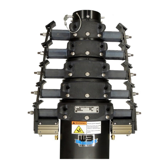
Pneumatic Mast with Remote Locking System
(Heavy Duty, Super Heavy Duty, and Ultra Heavy Duty Models)
The Will-Burt Company
401 Collins Blvd
Orrville, OH 44667, USA
Operating Instructions
Phone: +1 330 684 4000
E-Mail: info@willburt.com
Website: www.willburt.com
Authorized Representative:
Will-Burt Germany GmbH & Co. KG
Fischergasse 25
D-91344 Waischenfeld, Germany
(2.7-15m UHD RLS P/N: 710991590 Shown)
TP-5580101-A, February 2022
© 2022 The Will-Burt Company
Original Instructions
Advertisement
Table of Contents

Related Manuals for Will Burt 7-30 HDL

Summary of Contents for Will Burt 7-30 HDL
- Page 1 Pneumatic Mast with Remote Locking System Operating Instructions (Heavy Duty, Super Heavy Duty, and Ultra Heavy Duty Models) (2.7-15m UHD RLS P/N: 710991590 Shown) The Will-Burt Company Phone: +1 330 684 4000 TP-5580101-A, February 2022 401 Collins Blvd E-Mail: info@willburt.com ©...
- Page 3 PNEUMATIC MAST WITH REMOTE LOCKING SYSTEM OPERATING INSTRUCTIONS Warranty Will-Burt warrants its Pneumatic Mast with Remote Locking System to be free from defects in material and workmanship for a period of two (2) years, with such time period running from the date of shipment by Will-Burt.
-
Page 4: Table Of Contents
PNEUMATIC MAST WITH REMOTE LOCKING SYSTEM OPERATING INSTRUCTIONS Contents 1 Safety Summary....................5 1.1 Signal Word Definitions..................... 5 1.2 Safety Instructions ....................5 1.3 Symbols Used on Product Labels ................13 2 Specification Compliance ................. 15 2.1 CE Declaration of Conformity ................. 15 3 Introduction ...................... - Page 5 PNEUMATIC MAST WITH REMOTE LOCKING SYSTEM OPERATING INSTRUCTIONS 5.6 Mast Installation External Mount ................81 5.6.1 External Mount Quick Summary ..............82 5.6.2 External Mount Detailed Instructions ............83 5.6.2.1 Select a Suitable Mounting Location ............. 83 5.6.2.2 Install the Shelf Bracket (Optional)............84 5.6.2.3 Attach the Base Plate to the Mast ............
- Page 6 10.2 Drawings ......................151 10.3 System Wiring Diagram ..................151 10.4 Mast Wind Load Capacity ................... 153 10.4.1 Catalog Model 7-30 HDL ................154 10.4.2 Catalog Model 7-42 HDL ................155 10.4.3 Catalog Model 10-60 HDL ................ 156 10.4.4 Catalog Model 9-50 SHDL ................ 157 10.4.5 Catalog Model 10.3-60 SHDL ..............
-
Page 7: Safety Summary
PNEUMATIC MAST WITH REMOTE LOCKING SYSTEM OPERATING INSTRUCTIONS Safety Summary This section describes safety instructions for the Pneumatic Mast with Remote Locking System that personnel must understand and apply throughout all product activities such as transportation, handling, installation, operation, maintenance, storage, disposal troubleshooting. - Page 8 PNEUMATIC MAST WITH REMOTE LOCKING SYSTEM OPERATING INSTRUCTIONS Mast Tip Over Hazard! Mast tip over could result in death or serious injury. Before operation, be certain mounting structure is capable of resisting forces generated from all loading and environmental conditions, including, but not limited to, mast size and weight, payload and cable size and weight, payload sail area, wind speed, guy line arrangement, support bracket or roof line location, and base plate assembly.
- Page 9 PNEUMATIC MAST WITH REMOTE LOCKING SYSTEM OPERATING INSTRUCTIONS Trained Personnel Only! This product is intended for use by trained professionals only. It is not intended for general use by the public or untrained personnel. Handling, installation, operation and maintenance to be performed by trained and authorized personnel only. Only a properly trained and qualified certified electrician should perform electric installations and service.
- Page 10 PNEUMATIC MAST WITH REMOTE LOCKING SYSTEM OPERATING INSTRUCTIONS Health and Safety Hazard while Cleaning! Solvent used to clean parts is potentially dangerous. Avoid inhalation of fumes and prolonged contact to skin. Fire Hazard Solvent! Cleaning solvent, used for maintenance, is flammable and can be explosive.
- Page 11 PNEUMATIC MAST WITH REMOTE LOCKING SYSTEM OPERATING INSTRUCTIONS Equipment Damage - Submerged! Do not submerge mast in liquid or operate the vehicle in a fording situation that would result in a submerged mast. Safety Instruction – Keep Clear! Keep personnel clear of the system during operation. Safety Instruction - Potential Air Contaminants! If internally mounted in a vehicle, air from mast and any accumulated water will discharge into the vehicle.
- Page 12 PNEUMATIC MAST WITH REMOTE LOCKING SYSTEM OPERATING INSTRUCTIONS Tripping Hazard! Cables, trip lines, guy lines and guy anchors can be hard to see during and after installation. Any equipment posing trip hazards should be clearly marked. Lifting Hazard! Manually lifting over 55 lb. (25 kg) is prohibited. In the UK, all lifting equipment must be thoroughly examined annually by a competent person according to the Lifting Operations and Lift Equipment Regulations 1998.
- Page 13 PNEUMATIC MAST WITH REMOTE LOCKING SYSTEM OPERATING INSTRUCTIONS • 4° of vertical for payloads 600 lb. (272.2 kg) or less • 1° of verticals for payloads 600 lb. to 1,200 lb. (272.2 kg to 544.3 kg) All values assume a maximum of 12 inch (30.5 cm) payload offset. If offsetting any payload greater than 600 lb.
- Page 14 PNEUMATIC MAST WITH REMOTE LOCKING SYSTEM OPERATING INSTRUCTIONS Safety Instruction - Motion on Power Interruption or Emergency Stop! When using a normally open control valve as required for vehicle applications, if power is lost or turned off or the emergency stop is activated while the mast is extended, the mast will begin releasing air pressure and retracting at a controlled rate until power is restored or the mast fully retracts.
-
Page 15: Symbols Used On Product Labels
PNEUMATIC MAST WITH REMOTE LOCKING SYSTEM OPERATING INSTRUCTIONS Symbols Used on Product Labels The following symbols are displayed on the product. The symbol meanings are as follows: This symbol indicates an electrocution hazard or hazardous voltage hazard. There is voltage present inside mast and control box. Do not operate mast near electrical lines or during electrical storms. - Page 16 PNEUMATIC MAST WITH REMOTE LOCKING SYSTEM OPERATING INSTRUCTIONS PAGE 14 OF 164 TP-5580101-A FEBRUARY 2022...
-
Page 17: Specification Compliance
PNEUMATIC MAST WITH REMOTE LOCKING SYSTEM OPERATING INSTRUCTIONS Specification Compliance CE Declaration of Conformity Refer to the Product page at www.willburt.com for the latest Declaration of Conformity. The Pneumatic Mast with Remote Locking System conforms to CE standards when used with a CE approved control system. - Page 18 PNEUMATIC MAST WITH REMOTE LOCKING SYSTEM OPERATING INSTRUCTIONS PAGE 16 OF 164 TP-5580101-A FEBRUARY 2022...
-
Page 19: Introduction
PNEUMATIC MAST WITH REMOTE LOCKING SYSTEM OPERATING INSTRUCTIONS Introduction Thank you for selecting The Will-Burt Company for your critical payload elevation needs. These operating instructions describe the installation, operation, transportation, maintenance, storage, and troubleshooting procedures for the Pneumatic Mast with Remote Locking System (Heavy Duty, Super Heavy Duty, and Ultra Heavy Duty models). -
Page 20: Intended Use
PNEUMATIC MAST WITH REMOTE LOCKING SYSTEM OPERATING INSTRUCTIONS Intended Use The Pneumatic Mast with Remote Locking System is intended for use by professionals in the fire/ rescue/first responder/security/towing/cellular industries to provide elevated and directional emergency scene lighting and surveillance or communication capabilities. It is not intended for use by non-professionals. -
Page 21: Major Components
PNEUMATIC MAST WITH REMOTE LOCKING SYSTEM OPERATING INSTRUCTIONS Major Components This section describes major components of a mast system assuming the use of standard catalog masts systems with the Remote Locking System. Characteristics of components customized to meet customer-specific needs may vary. If necessary, contact The Will-Burt Company for additional details. -
Page 22: Telescoping Mast
PNEUMATIC MAST WITH REMOTE LOCKING SYSTEM OPERATING INSTRUCTIONS 3.3.1 Telescoping Mast The telescoping mast (Figure 3-1): • Is the structure used to raise the payload to an operational height. • Consists of concentric, nesting mast tubes. • Extends and retracts pneumatically. •... - Page 23 PNEUMATIC MAST WITH REMOTE LOCKING SYSTEM OPERATING INSTRUCTIONS The locking collar(s) (Figure 3-3): • Guide bearings to reduce friction when contact is made between the guide plate and the latch lever from the above intermediate tube • Uses heat-treated super pins and a close azimuth design •...
-
Page 24: Hardware Bag (P/N: 902853 Or 5032501)
PNEUMATIC MAST WITH REMOTE LOCKING SYSTEM OPERATING INSTRUCTIONS Components shipping with the mast include: • Hardware Bag (P/N: 902853 or 5032501) • Drain Kit (P/N: 902982) • Magnetic Warning Kit • Hold Down Leash • Mast Top Cover (P/N: 5063501 or 902989) •... - Page 25 PNEUMATIC MAST WITH REMOTE LOCKING SYSTEM OPERATING INSTRUCTIONS • Drain water and connect to the air supply line: • (2) Close Nipple ¼ Inch Brass (P/N: 900508) • (1) Brass Cross (P/N: 900516) • (1) Drain Cock #64-T (P/N: 900382) •...
-
Page 26: Drain Kit (P/N: 902982)
PNEUMATIC MAST WITH REMOTE LOCKING SYSTEM OPERATING INSTRUCTIONS 3.3.1.2 Drain Kit (P/N: 902982) The drain kit provides a means to route draining water away from the mast by attaching one end of the drain kit to the drain hole and the other end outside the mounting structure area. Water that has accumulated in the mast should be periodically drained, particularly after the mast has been exposed to rain, in order to prevent damage. -
Page 27: Magnetic Warning Kit
PNEUMATIC MAST WITH REMOTE LOCKING SYSTEM OPERATING INSTRUCTIONS 3.3.1.3 Magnetic Warning Kit The magnetic warning kit is a system designed to warn against moving a vehicle while the mast is partially or fully extended. The operator should always visually confirm that the mast is entirely retracted before moving the vehicle. - Page 28 PNEUMATIC MAST WITH REMOTE LOCKING SYSTEM OPERATING INSTRUCTIONS Table 3-2 Magnetic Warning Kit Description Quantity Clamp Magnet Assembly Switch Label Notice Label Warning Label Flasher Light Relay Carton (Not Shown) Table 3-3 Magnetic Warning Kit Description Quantity Notice Label Magnet Assembly Switch Switch Bracket Flasher...
-
Page 29: Hold Down Leash
PNEUMATIC MAST WITH REMOTE LOCKING SYSTEM OPERATING INSTRUCTIONS Magnetic Warning Kit Bracket Hose Clamp Screw Nyloc Nut Reed Switch Switch Assembly on Base Tube Switch Assembly Figure 3-6 Magnetic Warning Kit 3.3.1.4 Hold Down Leash The hold down leash is a wire cable that can be used to hold collars together for horizontal transportation, or used with a hold down platform to allow for partial extension of the mast. -
Page 30: Identification Plate (P/N: 902851)
PNEUMATIC MAST WITH REMOTE LOCKING SYSTEM OPERATING INSTRUCTIONS 3.3.1.6 Identification Plate (P/N: 902851) Information pertaining to the mast can be found on the identification plate secured to the third collar up or the base tube collar (Figure 3-8). Model Number Date of Assembly or Year of Manufacture Approximate... -
Page 31: Control System
PNEUMATIC MAST WITH REMOTE LOCKING SYSTEM OPERATING INSTRUCTIONS 3.3.2 Control System The Remote Locking System uses a control system to operate the mast. The available control systems are: • 9-40 VDC • 5572601 – RLS Mast Control System With Handheld •... - Page 32 PNEUMATIC MAST WITH REMOTE LOCKING SYSTEM OPERATING INSTRUCTIONS Figure 3-9 Control Box (Not to Scale) PAGE 30 OF 164 TP-5580101-A FEBRUARY 2022...
-
Page 33: Pneumatic System Options (Sold Separately)
PNEUMATIC MAST WITH REMOTE LOCKING SYSTEM OPERATING INSTRUCTIONS The HHRC (Figure 3-10): • Allows the operator to control the Pneumatic Mast with Remote Locking System from a distance (approximately 25 ft. from the control box). • Connects to the control box •... -
Page 34: Mounting Hardware Options (Sold Separately)
PNEUMATIC MAST WITH REMOTE LOCKING SYSTEM OPERATING INSTRUCTIONS 3.3.4 Mounting Hardware Options (Sold Separately) Mounting hardware is used to secure the mast in place. Possible options for the mounting hardware include: • Base Plate Options • Non-Rotatable Base Plate • Rotatable Hardware Kits •... - Page 35 PNEUMATIC MAST WITH REMOTE LOCKING SYSTEM OPERATING INSTRUCTIONS Screws from the hardware bag (Section 3.3.1.1) can be used to attach the non-rotating base plate to the base of the mast. Bolts, nuts, and washers from the hardware bag are sized for the through-holes in the corners of the base plate so the mast can be secured to a mounting surface.
- Page 36 PNEUMATIC MAST WITH REMOTE LOCKING SYSTEM OPERATING INSTRUCTIONS Note: The rotatable base plate assembly for a Super Heavy Duty mast does not use turning handles. Instead, rotating Super Heavy Duty masts have four holes spaced 90° apart in the tube head where a customer-supplied rod can be inserted to provide leverage to turn the mast.
-
Page 37: Support Bracket Options
PNEUMATIC MAST WITH REMOTE LOCKING SYSTEM OPERATING INSTRUCTIONS 3.3.4.2 Support Bracket Options The support bracket is used to secure the mast to a support structure. The support bracket can be an: • External Support Bracket • Internal (Roof) Mounting Kit External Support Bracket The external support bracket (Figure 3-17, Figure 3-18, and Figure 3-19) is used to position and support the mast. - Page 38 PNEUMATIC MAST WITH REMOTE LOCKING SYSTEM OPERATING INSTRUCTIONS External support brackets are also available for Super Heavy Duty masts (Figure 3-18). P/N: 909984 Shown P/N: 4894901 Shown Figure 3-18 Super Heavy Duty External Support Brackets External support brackets are also available for Ultra Heavy Duty masts (Figure 3-19). Ultra Heavy Duty support brackets contain shims and a washer plate which are used to allow for slight variation between mast tubes.
- Page 39 PNEUMATIC MAST WITH REMOTE LOCKING SYSTEM OPERATING INSTRUCTIONS Internal (Roof) Mounting Kit The internal mounting kit (P/N: 5476101) (Figure 3-23) contains the hardware used to position and support an internally mounted mast. Internal mounting kits are available for both non- rotatable and rotatable masts.
- Page 40 PNEUMATIC MAST WITH REMOTE LOCKING SYSTEM OPERATING INSTRUCTIONS Internal Mounting Kits for non-rotating Super Heavy Duty masts include: • (1) Roof Ring • (2) Gaskets • (1) Bearing Strip • (1) Ceiling Plate • (1) Retaining Ring • (1) O-Ring Retaining Ring Top of Mast Roof Ring...
- Page 41 PNEUMATIC MAST WITH REMOTE LOCKING SYSTEM OPERATING INSTRUCTIONS Internal Mounting Kits for the Ultra Heavy Duty Locking mast include: • (1) Roof Ring • (2) Gaskets • (1) Bearing Strip • (1) Ceiling Plate • (1) Retaining Ring • (1) O-Ring •...
-
Page 42: Shelf Bracket
PNEUMATIC MAST WITH REMOTE LOCKING SYSTEM OPERATING INSTRUCTIONS 3.3.4.3 Shelf Bracket The shelf bracket can be bolted into a support structure and used to position and support an externally mounted mast. Shelf brackets are available for use with both non-rotatable base plates and rotatable base plates and for various sized masts. - Page 43 PNEUMATIC MAST WITH REMOTE LOCKING SYSTEM OPERATING INSTRUCTIONS Payload Platform (P/N: 4051601 Shown) Payload Platform (P/N: 4079501 Shown) Payload Platform (P/N: 5002501 Shown) Figure 3-25 Payload Platform Examples (Not to Scale) Payload platforms are available both with through-holes to allow for quick installation of customer payloads, and without through-holes to allow the customer to drill through-holes to match payload-specific mounting hole patterns.
- Page 44 PNEUMATIC MAST WITH REMOTE LOCKING SYSTEM OPERATING INSTRUCTIONS For partial extension applications (Section 6.3.2.1) or applications transporting the mast horizontally (Section 7.1), The Will-Burt Company recommends the use of an optional hold down platform (ordered separately) with the hold down leashes (which ship with the mast). Hold Down Platform (P/N: 55451xx Shown) Hold Down Leash (P/N: 55191xx Shown) Figure 3-26 Hold Down Platform and Hold Down Leash (Not to Scale)
-
Page 45: Guy Line Options (Sold Separately)
PNEUMATIC MAST WITH REMOTE LOCKING SYSTEM OPERATING INSTRUCTIONS 3.3.6 Guy Line Options (Sold Separately) Guy line kits are used to further stabilize the mast by resisting environmental conditions that may cause tip-over and horizontal payload moment. Guy lines attach to guy lugs, which are located on the collars of the mast. -
Page 46: Additional Accessory Options (Sold Separately)
PNEUMATIC MAST WITH REMOTE LOCKING SYSTEM OPERATING INSTRUCTIONS 3.3.7 Additional Accessory Options (Sold Separately) The Will-Burt Company provides a number of additional accessory options (Table 3-5) for the mast system. Table 3-5 Additional Accessory Options Accessory Used To: Pneumatic Mast Antifreeze Kit Weatherize pneumatic masts in extremely harsh (P/N: 4725801) environmental conditions. -
Page 47: Technical Data
PNEUMATIC MAST WITH REMOTE LOCKING SYSTEM OPERATING INSTRUCTIONS Technical Data This section describes specifications for standard catalog masts only. Masts with other heights and capabilities are available. This section describes specifications for Pneumatic Masts with Remote Locking Systems as follows: •... -
Page 48: Heavy Duty Locking Masts
PNEUMATIC MAST WITH REMOTE LOCKING SYSTEM OPERATING INSTRUCTIONS Heavy Duty Locking Masts This section lists specifications for Heavy Duty Locking masts. Table 4-1 Heavy Duty Mast Part and Model Numbers *P/N 906043 7-30 906045 7-42 906051 10-60 *Part numbers listed for masts with a clear anodize finish only. Additional finishes and options available. Table 4-2 Heavy Duty Locking Mast Specifications Heavy Duty 7-30... - Page 49 PNEUMATIC MAST WITH REMOTE LOCKING SYSTEM OPERATING INSTRUCTIONS Table 4-2 Heavy Duty Locking Mast Specifications (Continued) Heavy Duty 7-30 7-42 10-60 Note: Tube Diameter listed as Base Tube Diameter – Top Tube Diameter Dimensions and specifications provided are for reference only and are not intended for vehicle design purposes Specifications may be subject to change without notice Payload Capacity assumes:...
-
Page 50: Super Heavy Duty Locking Masts
PNEUMATIC MAST WITH REMOTE LOCKING SYSTEM OPERATING INSTRUCTIONS Super Heavy Duty Locking Masts This section lists specifications for Super Heavy Duty Locking masts. Table 4-3 Super Heavy Duty Mast Part and Model Numbers *P/N 909959 9-50 909426 10.3-60 *Part numbers listed for masts with a clear anodize finish only. Additional finishes and options available. Table 4-4 Super Heavy Duty Locking Mast Specifications Super Heavy Duty 9-50... - Page 51 PNEUMATIC MAST WITH REMOTE LOCKING SYSTEM OPERATING INSTRUCTIONS Table 4-4 Super Heavy Duty Locking Mast Specifications (Continued) Super Heavy Duty 9-50 10.3-60 Note: Tube Diameter listed as Base Tube Diameter – Top Tube Diameter Dimensions and specifications provided are for reference only and are not intended for vehicle design purposes Specifications may be subject to change without notice Payload Capacity assumes:...
-
Page 52: Ultra Heavy Duty Locking Masts
PNEUMATIC MAST WITH REMOTE LOCKING SYSTEM OPERATING INSTRUCTIONS Ultra Heavy Duty Locking Masts This section lists specifications for Ultra Heavy Duty Locking masts. Table 4-5 Ultra Heavy Duty Locking Mast Part and Model Numbers *P/N 710991590 2.7-15 710991201 8-39 710905700 11.3-59 710992000 9.8-65.6... - Page 53 PNEUMATIC MAST WITH REMOTE LOCKING SYSTEM OPERATING INSTRUCTIONS Table 4-6 Ultra Heavy Duty Locking Mast Specifications (Continued) Ultra Heavy Duty 2.7-15 M 8-39 11.3-59 9.8-65.6 13-70 14.3-80 Maximum Operating Pressure Control Box Can 140 psi Handle Minimum Operating 20 psi Pressure for Locks Guying Required Optional...
-
Page 54: Installation Specifications
PNEUMATIC MAST WITH REMOTE LOCKING SYSTEM OPERATING INSTRUCTIONS Installation Specifications This section describes installation specifications as follows: • Mast Installation Specifications (Section 4.5.1) • Non-Rotating Base Plate Installation Specifications (Section 4.5.2) • Rotating Base Plate Installation Specifications (Section 4.5.3) • Turning Handle Assembly Installation Specifications (Section 4.5.4) •... -
Page 55: Mast Installation Specifications
PNEUMATIC MAST WITH REMOTE LOCKING SYSTEM OPERATING INSTRUCTIONS 4.5.1 Mast Installation Specifications Table 4-7 Mast Installation Specifications P/N* MODEL inch inch inch Heavy Duty Locking 906043 7-30 2134 68.3 1735 55.3 1405 906045 7-42 2337 68.4 1737 49.6 1260 906051 10-60 3099 101.1... - Page 56 PNEUMATIC MAST WITH REMOTE LOCKING SYSTEM OPERATING INSTRUCTIONS Drain Hole Figure 4-1 Mast Installation Specifications (Not to Scale) PAGE 54 OF 164 TP-5580101-A FEBRUARY 2022...
- Page 57 PNEUMATIC MAST WITH REMOTE LOCKING SYSTEM OPERATING INSTRUCTIONS Figure 4-2 Ultra Heavy Duty Mast Installation Specification (P/N: 710991590 Shown) TP-5580101-A PAGE 55 OF 164 FEBRUARY 2022...
- Page 58 PNEUMATIC MAST WITH REMOTE LOCKING SYSTEM OPERATING INSTRUCTIONS Figure 4-3 Ultra Heavy Duty Mast Installation Specification (P/N: 710908091 Shown) PAGE 56 OF 164 TP-5580101-A FEBRUARY 2022...
-
Page 59: Non-Rotating Base Plate Installation Specifications
PNEUMATIC MAST WITH REMOTE LOCKING SYSTEM OPERATING INSTRUCTIONS 4.5.2 Non-Rotating Base Plate Installation Specifications The non-rotating base plate: • Weighs approximately 9 lb. (4 kg) • Has the dimensions shown in Table 4-8 / Figure 4-4 and Figure 4-5. Table 4-8 Non-Rotating Base Plate Installation Specifications Ø... - Page 60 PNEUMATIC MAST WITH REMOTE LOCKING SYSTEM OPERATING INSTRUCTIONS 13.5 in (343 mm) 0.5 in 12 in (12.7 mm) 0.75 in (305 mm) (19 mm) Ø 0.563 in (14 mm) 45° 45° 12 in (305 mm) Ø 0.531 in (13.5 mm) BCD Ø...
-
Page 61: Rotating Base Plate Installation Specifications
PNEUMATIC MAST WITH REMOTE LOCKING SYSTEM OPERATING INSTRUCTIONS 4.5.3 Rotating Base Plate Installation Specifications Table 4-9 Rotating Base Plate Installation Specifications Est. Weight Base P/N* inch inch inch inch Tube 902364 6 ¾ 9 ¾ 0.38 12.4 902344 0.38 20.5 909983 11 ¼... -
Page 62: Turning Handle Assembly Installation Specifications
PNEUMATIC MAST WITH REMOTE LOCKING SYSTEM OPERATING INSTRUCTIONS 4.5.4 Turning Handle Assembly Installation Specifications Table 4-10 Turning Handle Assembly Installation Specifications P/N* Base Tube inch 914480 6 ¾ 906813 * Part Number is for the turning handles only and does not include the base plate. Part Numbers listed have a black paint finish. -
Page 63: Support Bracket Assembly Installation Specifications
PNEUMATIC MAST WITH REMOTE LOCKING SYSTEM OPERATING INSTRUCTIONS 4.5.5 Support Bracket Assembly Installation Specifications Table 4-11 Support Bracket Installation Specifications Est. Weight Base P/N* inch inch inch Tube 4443605 6 ¾ 7 ¾ 8 ¼ 12.10 4443615 10 ½ 9 ¾ 13.84 12.1 * Part Numbers for clear anodized finish. - Page 64 PNEUMATIC MAST WITH REMOTE LOCKING SYSTEM OPERATING INSTRUCTIONS 8 inches 19.68 inches 16.34 inches (415 mm) (203 mm) (500 mm) 13.68 inches 1.5 inches Ø 0.56 inches (38 mm) (14 mm) (347 mm) 4.0 inches 6.26 inches (102 mm) (159 mm) 3.13 inches 1.99 inches (80 mm)
- Page 65 PNEUMATIC MAST WITH REMOTE LOCKING SYSTEM OPERATING INSTRUCTIONS 5.38 inches (137 mm) 0.562 inches (14.3 mm) 12.75 15 inches inches (381 mm) (324 15 inches (381 mm) 9.75 inches 1.19 inches 1.19 (248 mm) (30 mm) inches (30 mm) 15.65 inches (398 mm) 1.5 inches (38 mm) inches...
- Page 66 PNEUMATIC MAST WITH REMOTE LOCKING SYSTEM OPERATING INSTRUCTIONS 13 in Ø 0.397 in (330 mm) (10 mm) 6.5 in (165 mm) 6.94 in (176 mm) 5.5 in (140 mm) 17.05 in (433 mm) 10 in (254 mm) 8.5 in 18 in (216 mm) (457 mm) Figure 4-11 External Support Bracket Assembly (Ultra Heavy Duty) Installation Specifications...
-
Page 67: Internal Mounting Kit Installation Specifications
PNEUMATIC MAST WITH REMOTE LOCKING SYSTEM OPERATING INSTRUCTIONS 4.5.6 Internal Mounting Kit Installation Specifications Table 4-12 Internal Mounting Kit (Roof Flange and Roof Ring) Installation Specifications Ø A Ø BCD Base P/N* inch inch inch inch Tube 905734 6 ¾ 9 ¾... - Page 68 PNEUMATIC MAST WITH REMOTE LOCKING SYSTEM OPERATING INSTRUCTIONS B number of 5/16 inch (8 mm) holes equally spaced on ØBCD Ø BCD Space for Roof Hardware Stack-Up Roof Flange Only Ø A (Base Tube Ø 5, 6 ¾, 9) Internal Support Bracket P/N: 905733 Shown B number of 5/16 inch (8 mm) holes equally spaced on ØBCD...
- Page 69 PNEUMATIC MAST WITH REMOTE LOCKING SYSTEM OPERATING INSTRUCTIONS Figure 4-13 describes the dimensions for the Ultra Heavy Duty’s internal mounting kit (P/N: 54761xx). 0.25 in (6 mm) Eight Ø 0.406 in (10 mm) 1.75 in Ø 15.25 in Holes equally spaced on the BCD (44 mm) (387 mm) BCD Hardware...
-
Page 70: Shelf Bracket Assembly Installation Specifications
PNEUMATIC MAST WITH REMOTE LOCKING SYSTEM OPERATING INSTRUCTIONS 4.5.7 Shelf Bracket Assembly Installation Specifications Table 4-13 Shelf Bracket Assembly Specifications Base Base P/N* inch inch inch inch inch Tube Plate** 4434101 11.8 10.5 6 ¾ 4454001 14.38 7.75 11.95 8.44 4454001 14.38 7.75... - Page 71 PNEUMATIC MAST WITH REMOTE LOCKING SYSTEM OPERATING INSTRUCTIONS Ø G Side View Front View Base Plate Mounting Holes Ø P Ø H Top Down View (Mounting Hole Pattern Shown in Simplified Form) Figure 4-14 Shelf Bracket Installation Specifications Note: For clarity purposes, the base plate mounting hole pattern shown (Figure 4-14) has been simplified.
-
Page 72: Control Box Installation Specifications
PNEUMATIC MAST WITH REMOTE LOCKING SYSTEM OPERATING INSTRUCTIONS 4.5.8 Control Box Installation Specifications The control box: • Weighs approximately 11.8 lb. • Has the dimensions shown in Figure 4-15. 14.1 in [357 mm] Figure 4-15 Control Box Installation Specifications (P/N: 5557301) Note: The customer can reorient the control box feet 90°... -
Page 73: Installation
PNEUMATIC MAST WITH REMOTE LOCKING SYSTEM OPERATING INSTRUCTIONS Installation This section describes the installation of the Pneumatic Mast with Remote Locking System and provides the general procedures that must be followed to ensure a successful installation. Be sure to read and understand the entire installation procedure and the Safety Summary in Section 1 before beginning installation. -
Page 74: Installation Equipment
PNEUMATIC MAST WITH REMOTE LOCKING SYSTEM OPERATING INSTRUCTIONS Installation Equipment Table 5-1 lists general equipment recommended for installation. Depending on the mast system configuration, additional equipment may be required. Table 5-1 Equipment Recommended for Installation Recommended Equipment* Personal Protective Safety Glasses Work Gloves Safety Shoes Hard Hat or Helmet... -
Page 75: Installation Hardware
PNEUMATIC MAST WITH REMOTE LOCKING SYSTEM OPERATING INSTRUCTIONS Installation Hardware This section describes hardware that may be used during installation as follows: • Table 5-2 Hardware for Internal Mount Application Installation • Table 5-3 Hardware for External Mount Application Installation •... - Page 76 PNEUMATIC MAST WITH REMOTE LOCKING SYSTEM OPERATING INSTRUCTIONS Table 5-2 Hardware for Internal Mount Application Installation (Continued) Hardware* Supplied By Notes Turning Handles (To Mast) Ships with Turning Handles (2) ¼-20x1.50 Hex HD Bolts The Will-Burt (P/N: 2000) Company Ships with Turning Handles The Will-Burt (2) ¼-20 Nyloc Nuts (P/N: 1930) Company...
- Page 77 PNEUMATIC MAST WITH REMOTE LOCKING SYSTEM OPERATING INSTRUCTIONS Table 5-3 Hardware for External Mount Application Installation Hardware* Supplied By Notes Shelf Bracket (Optional) (To the Support Structure) (4) Bolts Bolts should be sized to length to allow Customer for the thickness of the shelf bracket, support structure, and any spacers and (4) Flat Washers mounting hardware.
- Page 78 PNEUMATIC MAST WITH REMOTE LOCKING SYSTEM OPERATING INSTRUCTIONS Table 5-3 Hardware for External Mount Application Installation (Continued) Hardware* Supplied By Notes Non-Rotatable and Rotatable Base Plate (To the Mounting Surface) (4) ⅜-16x1-½ Inch Bolts The Will-Burt Found in the Hardware Bag (P/N: 901594) Company The Will-Burt...
- Page 79 PNEUMATIC MAST WITH REMOTE LOCKING SYSTEM OPERATING INSTRUCTIONS Table 5-4 Hardware for Ultra Heavy Duty Installation Hardware* Supplied By Notes Non-Rotatable Base Plate (To the Mast) (4) ½-13x1.25 Flathead The Will-Burt Found in the Hardware Bag Screws (P/N: 5402) Company External Support Bracket (To the Support Structure) The bolts should be sized to length to allow for the (6) Sets of ⅜...
-
Page 80: Lift The Mast System
PNEUMATIC MAST WITH REMOTE LOCKING SYSTEM OPERATING INSTRUCTIONS Table 5-4 (Continued)Hardware for Ultra Heavy Duty Installation Hardware* Supplied By Notes HHRC Holder (To the Mounting Structure) The bolts should be sized to length to allow for the (2) #8 (M4) Flathead thickness of the HHRC, support structure, any Customer Screws... - Page 81 PNEUMATIC MAST WITH REMOTE LOCKING SYSTEM OPERATING INSTRUCTIONS 3. Ensure all components are included and that the required tools are readily available. The components in the system shipment are shown in Table 5-5. The components your system includes will vary based upon your order. Table 5-5 Possible Components in the System Ship Telescoping Mast Hardware Bag (P/N:...
- Page 82 PNEUMATIC MAST WITH REMOTE LOCKING SYSTEM OPERATING INSTRUCTIONS Note: Do NOT apply pressure to the air cylinders when lifting. Lifting with weight on the air cylinders could damage the mast. Hoist Air Cylinders Sling COG Label Figure 5-3 Hoist the Mast The Will-Burt Company recommends keeping the shipping crate for transporting the mast, for example if shipping the mast back to the factory for refurbishment.
-
Page 83: Mast Installation External Mount
PNEUMATIC MAST WITH REMOTE LOCKING SYSTEM OPERATING INSTRUCTIONS Mast Installation External Mount This section describes installation of an externally mounted mast (Figure 5-4). The external mounting instructions assume the use of an external support bracket. For information on mounting the mast internally, see Section 5.7. Figure 5-4 Typical External Mount Application (Not to Scale) TP-5580101-A PAGE 81 OF 164... -
Page 84: External Mount Quick Summary
PNEUMATIC MAST WITH REMOTE LOCKING SYSTEM OPERATING INSTRUCTIONS 5.6.1 External Mount Quick Summary The following is a quick summary of installation of an externally mounted mast. Detailed steps follow the quick summary (Section 5.6.2). Install an externally mounted mast as follows: 1. -
Page 85: External Mount Detailed Instructions
PNEUMATIC MAST WITH REMOTE LOCKING SYSTEM OPERATING INSTRUCTIONS 5.6.2 External Mount Detailed Instructions The following are detailed steps of the installation of an externally mounted mast. The exact installation procedures may vary based on the configuration of the mast system being used and the installation environment. -
Page 86: Install The Shelf Bracket (Optional)
PNEUMATIC MAST WITH REMOTE LOCKING SYSTEM OPERATING INSTRUCTIONS 5.6.2.2 Install the Shelf Bracket (Optional) To install a shelf bracket (if used): 1. Position the shelf bracket ensuring the shelf bracket is level. 2. Use the shelf bracket as a template to drill holes through the support structure. 3. -
Page 87: Attach The Base Plate To The Mast
PNEUMATIC MAST WITH REMOTE LOCKING SYSTEM OPERATING INSTRUCTIONS 5.6.2.3 Attach the Base Plate to the Mast This section describes installing the mast and base plate. The exact procedures vary depending on whether the mast system uses a non-rotatable or rotatable base plate. Follow the appropriate installation instructions for your mast system. -
Page 88: Position The Mast
PNEUMATIC MAST WITH REMOTE LOCKING SYSTEM OPERATING INSTRUCTIONS 5.6.2.4 Position the Mast To position the mast: 1. Carefully move the mast into the desired mounting location. 2. Lower the mast the rest of the way to the mounting surface. 3. Carefully move the mast into position ensuring the mast is level. It is necessary to check the mast in two places 90°... - Page 89 PNEUMATIC MAST WITH REMOTE LOCKING SYSTEM OPERATING INSTRUCTIONS 2. Secure the external support bracket around the base tube with the hardware from the external support bracket kit. Do not overtighten the external support bracket and deform the base tube (doing this damages the mast). The mounting hardware must include proper means to resist vibration loosening, such as thread-locking compound or locking hardware.
- Page 90 PNEUMATIC MAST WITH REMOTE LOCKING SYSTEM OPERATING INSTRUCTIONS Ultra Heavy Duty: Install the External Support Bracket This section describes installation of the external support bracket. To allow for slight variation between mast tubes, the external support bracket has been designed to allow for adjustment of the tightness of the support bracket clamp.
- Page 91 PNEUMATIC MAST WITH REMOTE LOCKING SYSTEM OPERATING INSTRUCTIONS 4. Secure the external support bracket around the base tube as follows: a. Secure the mast temporarily in position to prevent it from leaning or falling throughout installation of the support bracket clamp. Ensure the mast is level and snug against the back of the external support bracket.
- Page 92 PNEUMATIC MAST WITH REMOTE LOCKING SYSTEM OPERATING INSTRUCTIONS d. The washer plate should be aligned so that its outside edge is flush with the outside edge of the support bracket clamp (Figure 5-7). If the outside edge sticks out beyond the edge of the support bracket clamp (Figure 5-7), it is installed backwards and needs flipped.
- Page 93 PNEUMATIC MAST WITH REMOTE LOCKING SYSTEM OPERATING INSTRUCTIONS f. Release the support bracket clamp and insert the estimated number of shims between the support bracket clamp and the support bracket weldment (Figure 5-9). Do not pull out on the support bracket clamp. If a shim does not easily fit between the support bracket clamp and support bracket weldment, that shim is not necessary, and should not be used.
- Page 94 PNEUMATIC MAST WITH REMOTE LOCKING SYSTEM OPERATING INSTRUCTIONS h. Tighten the left side. Ensure the external support bracket snuggly secures the mast without bending the support bracket clamp. If necessary, adjust the shims. Torque to 15.83-20 ft.- lb. (21-27 Nm). Note: If it is necessary to adjust the shims, they can be removed without completely loosening the hardware.
-
Page 95: Secure The Base Plate To The Mounting Surface
PNEUMATIC MAST WITH REMOTE LOCKING SYSTEM OPERATING INSTRUCTIONS 6. Ensure the mast system is level in all directions. If necessary, spacers may be added between the external support bracket and the support structure to keep the correct alignment between the external support bracket and the support structure. 7. -
Page 96: Install The Turning Handles (Rotatable Mast Systems Only)
PNEUMATIC MAST WITH REMOTE LOCKING SYSTEM OPERATING INSTRUCTIONS 5.6.2.7 Install the Turning Handles (Rotatable Mast Systems Only) Rotatable base plate kits for Heavy Duty masts ship with turning handles to assist in rotating the mast. Super Heavy Duty and Ultra Heavy Duty masts do not use turning handles. To secure the turning handles: 1. -
Page 97: Mast Installation: Internal Mount
PNEUMATIC MAST WITH REMOTE LOCKING SYSTEM OPERATING INSTRUCTIONS Mast Installation: Internal Mount This section describes installation of an internally mounted mast (Figure 5-13). These internal mounting instructions assume the use of an internal mounting kit (Section 3.3.4.2). For information on mounting the mast externally, see Section 5.6. Figure 5-13 Typical Internal Mount Application TP-5580101-A PAGE 95 OF 164... -
Page 98: Internal Mount: Quick Summary
PNEUMATIC MAST WITH REMOTE LOCKING SYSTEM OPERATING INSTRUCTIONS 5.7.1 Internal Mount: Quick Summary The following is a quick summary of the installation of an internally mounted mast. Detailed steps follow the quick summary (Section 5.7.2). Install an internally mounted mast as follows: 1. -
Page 99: Internal Mount Detailed Instructions
PNEUMATIC MAST WITH REMOTE LOCKING SYSTEM OPERATING INSTRUCTIONS 5.7.2 Internal Mount Detailed Instructions The following are detailed steps describing the installation of an internally mounted mast. The exact installation procedures may vary based on the configuration of the mast system being used and the installation environment. -
Page 100: Begin Installation Of The Internal Mounting Kit
PNEUMATIC MAST WITH REMOTE LOCKING SYSTEM OPERATING INSTRUCTIONS 5.7.2.2 Begin Installation of the Internal Mounting Kit To begin installation of the internal mounting kit: 1. Remove any roof liner or ceiling panels from the roof. 2. Cut a round hole in the roof ¼ inch (6.35 mm) larger than the diameter of the base tube (Section 4). - Page 101 PNEUMATIC MAST WITH REMOTE LOCKING SYSTEM OPERATING INSTRUCTIONS Retaining Ring Top of Mast Roof Ring Bearing Strip O-Ring Gaskets Ceiling Plate Roof Bottom of Mast Figure 5-16 Ultra Heavy Duty Internal Mounting Kit (P/N: 5476101) 4. If necessary, use washers or short spacers made of ¼ inch (6.35 mm) pipe to level out any irregularities that exist in the roof.
- Page 102 PNEUMATIC MAST WITH REMOTE LOCKING SYSTEM OPERATING INSTRUCTIONS d. Fasten this assembly (Figure 5-17) together using: i. ¼ Inch (M6) Bolts ii. ¼ Inch (M6) Lock Washers iii. ¼ Inch (M6) Nuts Figure 5-17 Fasten Assembly Together The bolts should be sized to length to account for all components. The mounting hardware must include proper means to resist vibration loosening such as thread-locking compound or locking hardware.
- Page 103 PNEUMATIC MAST WITH REMOTE LOCKING SYSTEM OPERATING INSTRUCTIONS For Super Heavy Duty and Ultra Heavy Duty masts: a. Line up the holes in the roof, gasket, and roof ring (Figure 5-16). Ensure the gasket is between the roof and roof ring. Leave the retaining ring and o-ring off. These will be installed later.
-
Page 104: Lower Mast Through The Internal Mounting Kit
PNEUMATIC MAST WITH REMOTE LOCKING SYSTEM OPERATING INSTRUCTIONS e. For non-rotatable mast systems, slide the retaining ring and o-ring over the bottom of the base tube and up the mast past the drain hole towards the collar. If they are difficult to maneuver, put soapy water on the mast to allow them to slide more freely. -
Page 105: Position The Mast
PNEUMATIC MAST WITH REMOTE LOCKING SYSTEM OPERATING INSTRUCTIONS Rotatable Base Plates To install a rotatable base plate: 1. Back the locking screws far enough out of the base plate to allow the base plate to fit over the end of the mast. 2. -
Page 106: Complete Installation Of The Internal Mounting Kit
PNEUMATIC MAST WITH REMOTE LOCKING SYSTEM OPERATING INSTRUCTIONS 5.7.2.7 Complete Installation of the Internal Mounting Kit This section describes completing the installation of the Internal Mounting Kit as follows: • Non-Rotatable Heavy Duty Masts • Non-Rotatable Super Heavy Duty and Ultra Heavy Duty Masts •... - Page 107 PNEUMATIC MAST WITH REMOTE LOCKING SYSTEM OPERATING INSTRUCTIONS 5. Fasten this assembly (Figure 5-19) together using: a. (8) ¼ Inch (M6) Bolts b. (8) ¼ Inch Lock Washers c. (8) ¼ Inch Nuts The mounting hardware must include proper means to resist vibration loosening such as thread- locking compound or locking hardware.
- Page 108 PNEUMATIC MAST WITH REMOTE LOCKING SYSTEM OPERATING INSTRUCTIONS Rotatable Super Heavy Duty Masts This section describes installing the flashing kit. If retrofitting a mast to use a flashing kit, see Installing the Internal Mount Flashing Kit (TP-5351001). To obtain this document, contact The Will-Burt Company.
- Page 109 PNEUMATIC MAST WITH REMOTE LOCKING SYSTEM OPERATING INSTRUCTIONS Turning Handles Turning handles ship with rotatable base plates to assist in rotating the mast. Note that rotating Super Heavy Duty masts do not use turning handles. To secure the turning handles: 1.
-
Page 110: Install The Control And Pneumatic Systems
PNEUMATIC MAST WITH REMOTE LOCKING SYSTEM OPERATING INSTRUCTIONS Install the Control and Pneumatic Systems This section describes general procedures and concepts to keep in mind when installing the control and pneumatic systems. Depending on the components of the mast system and the environment, the exact configuration and procedures may vary. -
Page 111: Control And Pneumatic Systems Installation Detailed Instructions
PNEUMATIC MAST WITH REMOTE LOCKING SYSTEM OPERATING INSTRUCTIONS 5.8.2 Control and Pneumatic Systems Installation Detailed Instructions The following are detailed steps of installation of the Control and Pneumatic Systems. The exact installation procedures may vary based on the configuration of the mast system being used and the installation environment. - Page 112 PNEUMATIC MAST WITH REMOTE LOCKING SYSTEM OPERATING INSTRUCTIONS 3. Attach the brass cross to the desired air inlet port with a close Nipple, ⅜ x ¼ bushing, and ½ x ⅜ bushing (Figure 5-20). Apply PTFE Tape to all threaded joints. If necessary, air hose may be used to connect between the air inlet port and the brass cross, however, the brass cross should be installed as close to the mast as possible to ensure proper drainage.
-
Page 113: Install The Air Supply
PNEUMATIC MAST WITH REMOTE LOCKING SYSTEM OPERATING INSTRUCTIONS 5.8.2.2 Install the Air Supply When installing, keep the following in mind: • Mounting: When mounting the pneumatic system, leave enough space around the unit for ventilation and for access to make initial installation, periodic adjustments, and future maintenance procedures as easy as possible. -
Page 114: Install The Control Box
PNEUMATIC MAST WITH REMOTE LOCKING SYSTEM OPERATING INSTRUCTIONS 5.8.2.3 Install the Control Box The control box can be installed outside or inside an enclosure such as the cab of a vehicle. When installing, ensure adequate space is available around the control box to allow for connection of air hoses and electrical cables. -
Page 115: Connect The Air Supply To The Control Box
PNEUMATIC MAST WITH REMOTE LOCKING SYSTEM OPERATING INSTRUCTIONS 5.8.2.4 Connect the Air Supply to the Control Box To connect the air supply to the control box: 1. Route a ⅜ inch air hose from the air supply to the control box. A filter regulator lubricator or filter lubricator can be run in-line between the air supply and the control box. -
Page 116: Connect The Control Box To The Mast
PNEUMATIC MAST WITH REMOTE LOCKING SYSTEM OPERATING INSTRUCTIONS 5.8.2.5 Connect the Control Box to the Mast To connect the control box to the mast: 1. Remove the RLS Guard. 2. Connect the ⅜ inch air hose (P/N: 108768) to the “MAST” connection on the control box (Figure 5-23). -
Page 117: Exhaust The Control Box (Optional)
PNEUMATIC MAST WITH REMOTE LOCKING SYSTEM OPERATING INSTRUCTIONS 10. Connect the sensor cable (P/N: 5567601) to the “SENSOR” connection on the control box (Figure 5-23). 11. Route the sensor cable to the mast so that it can reach the reed switches on the locks. If routing the sensor cable through a structure, The Will-Burt Company recommends the use of a grommet or equivalent to protect the sensor cable. -
Page 118: Connect The Hhrc To The Control Box (Optional Installation)
PNEUMATIC MAST WITH REMOTE LOCKING SYSTEM OPERATING INSTRUCTIONS 5.8.2.7 Connect the HHRC to the Control Box (Optional Installation) If desired, the mast can be operated using an HHRC instead of directly through the control box. To connect the HHRC, plug the HHRC into the “REMOTE” plug on the control box (Figure 5-25). REMOTE Connection Figure 5-25 Control Box “REMOTE”... - Page 119 PNEUMATIC MAST WITH REMOTE LOCKING SYSTEM OPERATING INSTRUCTIONS To secure the HHRC holder: 1. Use the holder as a guide to drill two holes on the mounting structure. 2. Secure the holder in place with two #8 (M4) flathead screws. Note: To use the HHRC to control the mast, it will be necessary to select “REMOTE”...
-
Page 120: Connect Customer Power To The Control Box
PNEUMATIC MAST WITH REMOTE LOCKING SYSTEM OPERATING INSTRUCTIONS 5.8.2.8 Connect Customer Power to the Control Box The control box does not have a master power switch. If a master power switch is desired, the customer must provide it in-line with the customer power. When wiring the customer power, be certain to observe any local codes or regulations. -
Page 121: Install The Drain Kit
PNEUMATIC MAST WITH REMOTE LOCKING SYSTEM OPERATING INSTRUCTIONS Install the Drain Kit The drain kit is intended to protect the interior of a vehicle from damage due to water drainage, and is optional for externally mounted masts. However, the elbow from the kit may be used to shield the drain hole from blowing sand, dust, and other debris. - Page 122 PNEUMATIC MAST WITH REMOTE LOCKING SYSTEM OPERATING INSTRUCTIONS 2. Fasten the hose adaptor to the drain hole (Figure 5-29). Apply PTFE Tape to all threaded joints. Turn the hose adaptor in ONLY 1 ½ to 2 times after initial engagement of the threads. Turning further will damage the mast.
-
Page 123: 5.10 Install The Magnetic Warning Kit
PNEUMATIC MAST WITH REMOTE LOCKING SYSTEM OPERATING INSTRUCTIONS 5.10 Install the Magnetic Warning Kit When installing the mast system on a vehicle, the magnetic warning kit shall be installed to provide a warning against moving the vehicle while the mast is partially or fully extended. When correctly installed, flashing lights will indicate partial or full extension of the mast when the ignition is on. - Page 124 PNEUMATIC MAST WITH REMOTE LOCKING SYSTEM OPERATING INSTRUCTIONS 5. Attach the magnetic switch assembly loosely around the base tube approximately 6 to 20 inches (15 to 51 cm) above the base plate (Figure 5-31). The magnetic switch assembly can be located anywhere around the perimeter of the base tube. Stainless Steel Band Magnetic Switch Base Tube...
- Page 125 PNEUMATIC MAST WITH REMOTE LOCKING SYSTEM OPERATING INSTRUCTIONS a. 7-30: Use 16 AWG stranded wire (customer-supplied) to connect the flasher and lights to the wires exiting the magnetic switch assembly (Figure 5-32). Customer-Supplied String or Wire. Remove Excess. Magnetic Switch Assembly “MAGNETIC SWITCH ASSEMBLY KIT”...
- Page 126 PNEUMATIC MAST WITH REMOTE LOCKING SYSTEM OPERATING INSTRUCTIONS 16 AWG to Flasher Relay (Bottom View) 16 AWG to Ignition Switch 16 AWG to Ground 16 AWG Magnetic Switch Feed Wires Through Grommet Assembly Magnetic Switch Wire Nuts Figure 5-34 Relay and Magnetic Switch Assembly Wiring 10.
-
Page 127: 5.11 Additional Accessory Installation
PNEUMATIC MAST WITH REMOTE LOCKING SYSTEM OPERATING INSTRUCTIONS 5.11 Additional Accessory Installation Depending on the configuration of the mast system, optional components selected, or the installation environment, additional accessories and positioners may need to be installed. Install any additional accessories as appropriate. Contact The Will-Burt Company with any questions before performing any installation procedures. -
Page 128: 5.13 Install Payload
PNEUMATIC MAST WITH REMOTE LOCKING SYSTEM OPERATING INSTRUCTIONS 5.13 Install Payload The exact installation procedures for payload will vary based on the customer-specific payload and payload platform or stud adaptor being used. For optimal performance, center the payload as best as possible. If offsetting any payload greater than 600 lb. (272 kg), the payload offset direction must be in-line with the tube keys, and not perpendicular to the keys. -
Page 129: Operation
PNEUMATIC MAST WITH REMOTE LOCKING SYSTEM OPERATING INSTRUCTIONS Operation This section describes the general operation of the mast system. Use care to understand and follow all precautions while operating. Pre-Operation Check Before operating the mast system, ensure: • All operators read and understand the entire operation procedure and are properly trained. •... -
Page 130: Operation Equipment
PNEUMATIC MAST WITH REMOTE LOCKING SYSTEM OPERATING INSTRUCTIONS Operation Equipment Table 6-1 lists recommended equipment for operation. Table 6-1 Equipment Recommended for Operation Recommended Equipment* Personal Protective Safety Glasses Work Gloves Nitrile or Vinyl Gloves Hearing Protection Hard Hat or Helmet Safety Shoes * Depending on the local, regional, and national standards and codes of practice, and the environment, additional personal protective equipment may be necessary. -
Page 131: Prepare The System
PNEUMATIC MAST WITH REMOTE LOCKING SYSTEM OPERATING INSTRUCTIONS 6.3.1 Prepare the System To prepare the system for operation: • Ensure the mast system is stationary on level, stable ground. • Perform the Pre-Operation Check (Section 6.1) • Prepare the pneumatic system for operation. As part of this: •... -
Page 132: Partial Extension Applications
PNEUMATIC MAST WITH REMOTE LOCKING SYSTEM OPERATING INSTRUCTIONS 6.3.2.1 Partial Extension Applications This section describes applications using partial extension of the mast assuming the use of a hold down platform and two hold down leashes (Section 3.3.5). Note that masts with 6.75-inch base tubes only have and require one hold down leash. - Page 133 PNEUMATIC MAST WITH REMOTE LOCKING SYSTEM OPERATING INSTRUCTIONS 5. Secure the second hold down leash to a new guy lug on the desired mast collar. The guy lug on the desired collar should be in-line with the lug on the hold down platform. During mast extension, the sections between the connection points will be prevented from fully extending and settle once air is exhausted.
-
Page 134: Mast Extension Procedures
PNEUMATIC MAST WITH REMOTE LOCKING SYSTEM OPERATING INSTRUCTIONS 6.3.2.2 Mast Extension Procedures To extend the mast: 1. Prepare the mast system for operation (Section 6.3.1). 2. Remove the mast top cover. 3. Secure the payload to the mast (Section 5.13). 4. - Page 135 PNEUMATIC MAST WITH REMOTE LOCKING SYSTEM OPERATING INSTRUCTIONS 8. If operating the mast from the control box, select “BOX” on the control box. The “BOX/ REMOTE” switch is a maintained switch and will keep its position. If operating the mast from the HHRC, select “REMOTE” on the control box. If operating manually (typically an emergency operation when power is not available): a.
- Page 136 PNEUMATIC MAST WITH REMOTE LOCKING SYSTEM OPERATING INSTRUCTIONS 12. If guy lines are used, properly secure and tension the guy lines immediately after raising the mast. All guy lines should be equally tensioned. Beginning at two locations opposite each other, gradually tension each guy line. Vertical alignment of the mast is accomplished by observing the mast perpendicularly to the two guy lines being tensioned to ensure the mast is standing straight, and is not bending too far towards one side (Figure 6-3).
-
Page 137: Lower The Mast
PNEUMATIC MAST WITH REMOTE LOCKING SYSTEM OPERATING INSTRUCTIONS 6.3.3 Lower the Mast To lower the mast: 1. Ensure the payload will have enough clearance when nested. 2. Close the drain cock. 3. If guy lines are used, decrease the tension on the guy lines until there is slack in the lines. Never attempt to unlock a mast collar with tension on the guy lines above it. - Page 138 PNEUMATIC MAST WITH REMOTE LOCKING SYSTEM OPERATING INSTRUCTIONS 6. Select “DOWN” to lower the mast. The “DOWN” function on the “UP/DOWN” switch is maintained. Air will be applied to the mast (35 psi) to lift the weight off the latch pins and to the locks (15 psi) to unlock the latch pins.
-
Page 139: Transportation
PNEUMATIC MAST WITH REMOTE LOCKING SYSTEM OPERATING INSTRUCTIONS Transportation Before transporting the mast system, the mast system needs to be secured. The exact procedures for transportation will vary based on the mast system configuration. The process described in this manual represents a possible method of transporting the mast. Depending on the environment and equipment available, other methods may work better. -
Page 140: Shipping
PNEUMATIC MAST WITH REMOTE LOCKING SYSTEM OPERATING INSTRUCTIONS Shipping When shipping the mast system, The Will-Burt Company recommends shipping the mast in the original shipping crate. If the original shipping crate is not available, contact The Will-Burt Company to order a replacement. When shipping: 1. -
Page 141: Maintenance And Adjustments
PNEUMATIC MAST WITH REMOTE LOCKING SYSTEM OPERATING INSTRUCTIONS Maintenance and Adjustments This section describes maintenance and adjustment procedures required to keep the mast system operational. Use care to understand and follow all precautions listed in the Safety Summary in Section 1 while performing these procedures. If the system does not perform as required, see Section 9. -
Page 142: Maintenance Equipment
PNEUMATIC MAST WITH REMOTE LOCKING SYSTEM OPERATING INSTRUCTIONS Maintenance Equipment Table 8-1 lists recommended equipment for maintenance. Table 8-1 Equipment Recommended for Maintenance Recommended Equipment* Personal Protective Safety Glasses Work Gloves Safety Shoes Hard Hat or Helmet Hearing Protection Nitrile or Vinyl Gloves Hand Tools Chisel Drill... -
Page 143: Replacement Parts
PNEUMATIC MAST WITH REMOTE LOCKING SYSTEM OPERATING INSTRUCTIONS Replacement Parts To order spare or replacement parts, always refer to the mast model number and serial number. The model number, serial number, and additional information is engraved on the mast identification plate (Section 3.3.1.6). Throughout this manual, “P/N” followed by a number represents the part number for that component. -
Page 144: Mast Cleaning And Lubrication
PNEUMATIC MAST WITH REMOTE LOCKING SYSTEM OPERATING INSTRUCTIONS Table 8-2 Periodic Inspections Frequency Inspection Action Monthly Inspect all hardware to ensure Tighten or replace any loose, fasteners are not damaged, damaged or missing fasteners. loosening, backing out or missing. Take special note of hardware keeping the payload mounted, mast collar bolts, and hardware used to mount the mast to the support... - Page 145 PNEUMATIC MAST WITH REMOTE LOCKING SYSTEM OPERATING INSTRUCTIONS To clean the mast: 1. Secure the hold down leashes so that only the top tube can extend. Note: Masts with 6.75- inch base tubes only have and require one hold down leash. 2.
-
Page 146: Weatherizing
PNEUMATIC MAST WITH REMOTE LOCKING SYSTEM OPERATING INSTRUCTIONS 8.4.2 Weatherizing For weatherizing your mast in extremely harsh environmental conditions, The Will-Burt Company recommends following the Weatherizing Instructions for Pneumatic Masts (TP-4744301). See www.willburt.com for these instructions. These instructions assume the use of the Pneumatic Mast Antifreeze Kit (P/N: 4725801). -
Page 147: Special Procedure: Reed Switch Adjustment
PNEUMATIC MAST WITH REMOTE LOCKING SYSTEM OPERATING INSTRUCTIONS Special Procedure: Reed Switch Adjustment When the locks are unlocked, the light on each reed switch should illuminate. When the locks are locked, the lights on the reed switches should not illuminate. If a light does not illuminate when the locks are unlocked or illuminates when the locks are locked, the reed switch needs adjusted. - Page 148 PNEUMATIC MAST WITH REMOTE LOCKING SYSTEM OPERATING INSTRUCTIONS PAGE 146 OF 164 TP-5580101-A FEBRUARY 2022...
-
Page 149: Troubleshooting
PNEUMATIC MAST WITH REMOTE LOCKING SYSTEM OPERATING INSTRUCTIONS Troubleshooting This section describes troubleshooting for the mast system. Use care to understand and follow all precautions while troubleshooting the mast system. Table 9-1 Troubleshooting Problem Possible Cause Possible Solution Mast is frozen in the extended position 1. - Page 150 PNEUMATIC MAST WITH REMOTE LOCKING SYSTEM OPERATING INSTRUCTIONS Table 9-1 Troubleshooting (Continued) Problem Possible Cause Possible Solution Mast will not lower without rocking 1. See section for mast cleaning and lubrication. Not enough weight. 2. Add weight to platform or stub adaptor.
-
Page 151: 10 References
PNEUMATIC MAST WITH REMOTE LOCKING SYSTEM OPERATING INSTRUCTIONS 10 References This section provides reference information for the system as follows: • Extended Glossary of Terms (Section 10.1) • Drawings (Section 10.2) • System Wiring Diagram (Section 10.3) • Mast Wind Load Capacity (10.4) 10.1 Extended Glossary of Terms This section defines terms used within this manual as follows: •... - Page 152 PNEUMATIC MAST WITH REMOTE LOCKING SYSTEM OPERATING INSTRUCTIONS • Intermediate Tubes: refer to the tubes between the base tube and the top tube. When referencing intermediate tubes, they are referenced from bottom to top. In context of the entire mast, tubes would be listed from bottom to top as: base tube, first intermediate tube, second intermediate tubes, etc., top tube.
-
Page 153: Mounting Position Terms
PNEUMATIC MAST WITH REMOTE LOCKING SYSTEM OPERATING INSTRUCTIONS 10.1.2 Mounting Position Terms For the purposes of this manual, regions of the mounting location are defined as follows: • Mounting Structure: the overall structure where the mast is mounted. • Mounting Surface: the surface to which the base plate is secured. When installing inside a vehicle, this will likely be the floor. - Page 154 PNEUMATIC MAST WITH REMOTE LOCKING SYSTEM OPERATING INSTRUCTIONS PAGE 152 OF 164 TP-5580101-A FEBRUARY 2022...
-
Page 155: 10.4 Mast Wind Load Capacity
PNEUMATIC MAST WITH REMOTE LOCKING SYSTEM OPERATING INSTRUCTIONS 10.4 Mast Wind Load Capacity The following graphs define the survival wind speed capacity as a function of payload sail area. Note carefully the assumptions at the bottom of each graph. If your payload application exceeds any of these assumption values, contact The Will-Burt Company’s Engineering for the wind load capacity for your specific application. -
Page 156: Catalog Model 7-30 Hdl
Survival Wind Speed Performance Curve Mast Guying Kit • 7-30 HDL Pneumatic Mast with Remote Locking System • WB P/N: 906162 • Nest Height = 7 ft. 0 in. [2.12 m] • 2-level, 4-way guying to 3.75" and 5.25" collars •... -
Page 157: Catalog Model 7-42 Hdl
PNEUMATIC MAST WITH REMOTE LOCKING SYSTEM OPERATING INSTRUCTIONS 10.4.2 Catalog Model 7-42 HDL 7-42 Heavy Duty Locking Pneumatic Mast with Remote Locking System Survival Wind Speed Performance Curve Mast Guying Kit • 7-42 HDL Pneumatic Mast with Remote Locking System •... -
Page 158: Catalog Model 10-60 Hdl
PNEUMATIC MAST WITH REMOTE LOCKING SYSTEM OPERATING INSTRUCTIONS 10.4.3 Catalog Model 10-60 HDL 10-60 Heavy Duty Locking Pneumatic Mast with Remote Locking System Survival Wind Speed Performance Curve Mast Guying Kit • 10-60 HDL Pneumatic Mast with Remote Locking System •... -
Page 159: Catalog Model 9-50 Shdl
PNEUMATIC MAST WITH REMOTE LOCKING SYSTEM OPERATING INSTRUCTIONS 10.4.4 Catalog Model 9-50 SHDL 9-50 Super Heavy Duty Locking Pneumatic Mast with Remote Locking System Survival Wind Speed Performance Curve Mast Guying Kit • 9-50 SHDL Pneumatic Mast with Remote Locking System •... -
Page 160: Catalog Model 10.3-60 Shdl
PNEUMATIC MAST WITH REMOTE LOCKING SYSTEM OPERATING INSTRUCTIONS 10.4.5 Catalog Model 10.3-60 SHDL 10.3-60 Super Heavy Duty Locking Pneumatic Mast with Remote Locking System Survival Wind Speed Performance Curve Mast Guying Kit • 10.3-60 SHDL Pneumatic Mast with Remote Locking System •... -
Page 161: Catalog Model 8-39 Uhdl
PNEUMATIC MAST WITH REMOTE LOCKING SYSTEM OPERATING INSTRUCTIONS 10.4.6 Catalog Model 8-39 UHDL 8-39 Ultra Heavy Duty Locking Pneumatic Mast with Remote Locking System Survival Wind Speed Performance Curve Mast Guying Kit • 8-39 UHDL Pneumatic Mast with Remote Locking System •... -
Page 162: Catalog Model 11.3-59 Uhdl
PNEUMATIC MAST WITH REMOTE LOCKING SYSTEM OPERATING INSTRUCTIONS 10.4.7 Catalog Model 11.3-59 UHDL 11.3-59 Ultra Heavy Duty Locking Pneumatic Mast with Remote Locking System Survival Wind Speed Performance Curve Mast Guying Kit • 11.3-59 UHDL Pneumatic Mast with Remote Locking System •... -
Page 163: Catalog Model 3-20M Uhdl
PNEUMATIC MAST WITH REMOTE LOCKING SYSTEM OPERATING INSTRUCTIONS 10.4.8 Catalog Model 3-20M UHDL 3-20M Ultra Heavy Duty Locking Pneumatic Mast with Remote Locking System Survival Wind Speed Performance Curve Mast Guying Kit • 3-20M UHDL Pneumatic Mast with Remote Locking System •... -
Page 164: Catalog Model 14.3-80 Uhdl
PNEUMATIC MAST WITH REMOTE LOCKING SYSTEM OPERATING INSTRUCTIONS 10.4.9 Catalog Model 14.3-80 UHDL 14.3-80 Ultra Heavy Duty Locking Pneumatic Mast with Remote Locking System Survival Wind Speed Performance Curve 1/4” STL Guying Kit Mast 3/16” STL Guying Kit • WB P/N: 5365901 •... -
Page 165: 11 Document History
PNEUMATIC MAST WITH REMOTE LOCKING SYSTEM OPERATING INSTRUCTIONS 11 Document History Table 11-1 Document History Changes Backward Document Compatible Date Change Details Revision with Previous Manual Version TP-5580101-00 1/14/2019 Initial Release. Added Heavy Duty with RLS and Super TP-5580101-A Feb. 2022 Heavy Duty with RLS information. - Page 166 PNEUMATIC MAST WITH REMOTE LOCKING SYSTEM OPERATING INSTRUCTIONS PAGE 164 OF 164 TP-5580101-A FEBRUARY 2022...
Need help?
Do you have a question about the 7-30 HDL and is the answer not in the manual?
Questions and answers