
Subscribe to Our Youtube Channel
Related Manuals for Inficon Transpector XPR 3+


Summary of Contents for Inficon Transpector XPR 3+
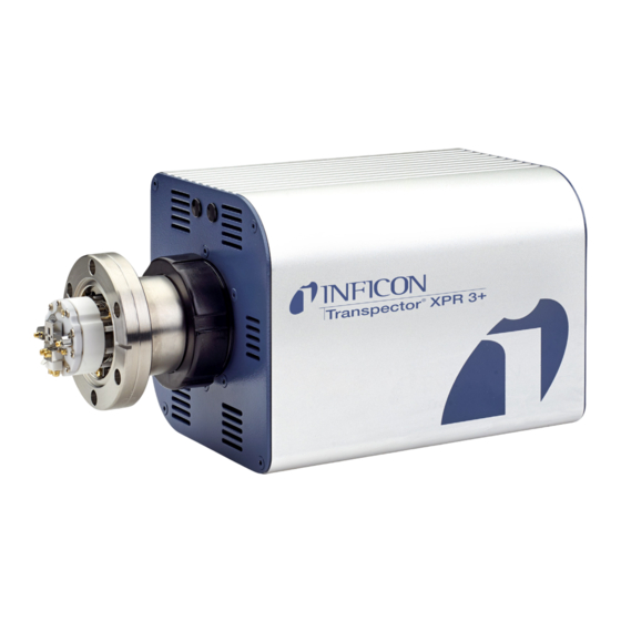
- Page 1 Cover Page ® Transpector XPR 3+ Gas Analysis System PN 074-687-P1A...
- Page 2 Declaration Of Conformity Page 1...
- Page 3 The information contained in this Operating Manual is believed to be accurate and reliable. However, INFICON assumes no responsibility for its use and shall not be liable for any special, incidental, or consequential damages related to the use of this product.
-
Page 4: Table Of Contents
1.3.1 Returning Transpector XPR 3+ to INFICON ......1-3 Quick Start ..........1-3 Purpose of Transpector XPR 3+ Gas Analysis System . - Page 5 Transpector XPR 3+ Operating Manual 1.13.5 Humidity ........... . 1-8 1.14 Computer System Requirements .
- Page 6 Transpector XPR 3+ Operating Manual Scanning Characteristics ........3-10 The Zero Blast .
- Page 7 Pirani Interlock Adjustment Procedures ......7-10 7.7.1 INFICON PSG500 Adjustment Instructions ......7-10 Chapter 8 Diagnosing Problems Introduction.
- Page 8 Transpector XPR 3+ Operating Manual Chapter 12 Specifications 12.1 Introduction..........12-1 12.2 Mass Range .
-
Page 9: Getting Started
Transpector XPR 3+ Operating Manual Chapter 1 Getting Started 1.1 Introduction Transpector XPR 3+ Gas Analysis System is a quadrupole-based mass spectrometer Residual Gas Analysis (RGA) instrument designed for use in high vacuum environments, up to 20 mTorr, for monitoring trace contaminants and ®... -
Page 10: Warning And Caution Paragraphs
This is an example of a Electrical Warning paragraph. It warns of the presence of electrical voltages which may cause bodily injury. 1.3 How To Contact Customer Support Worldwide customer support information is available under Contact >> Support Worldwide at www.inficon.com: Sales and Customer Service Technical Support Repair Service ... -
Page 11: Returning Transpector Xpr 3+ To Inficon
Transpector XPR 3+ Operating Manual 1.3.1 Returning Transpector XPR 3+ to INFICON Do not return any component of Transpector XPR 3+ to INFICON before speaking with a Customer Support Representative and obtaining a Return Material Authorization (RMA) number. Transpector XPR 3+ will not be serviced without an RMA number. -
Page 12: General Description Of Transpector Xpr
Transpector XPR 3+ Operating Manual Transpector XPR 3+ is an important aid in the efficient use of a high-vacuum system, detecting leaks, and contaminants. It can indicate the partial pressures of gases in processes occurring within a vacuum or other vessel, and therefore, can be used to investigate the nature of a process or monitor process conditions. -
Page 13: Physical Requirements
Transpector XPR 3+ Operating Manual 1.9 Physical Requirements The following sections show the physical dimensions, weight, mounting requirements, ventilation requirements, and the perimeter required for maintenance access for Transpector XPR 3+. 1.9.1 Physical Dimensions Figure 1-2 shows the overall physical dimensions of Transpector XPR 3+ in inches [millimeters]. -
Page 14: Weight
Transpector XPR 3+ Operating Manual 1.9.2 Weight Transpector XPR 3+ electronics module weighs 1.62 kg (3.58 lbs). 1.9.3 Mounting Requirements The sensor is mounted to a high-vacuum chamber with a standard 2.75 in. (69.9 mm) O.D. ConFlat flange. The electronics module attaches to and is supported by the sensor. Transpector XPR 3+ can be mounted in any position. -
Page 15: Overvoltage Category
Transpector XPR 3+ Operating Manual Figure 1-3 Transpector XPR 3+ connections Electrical Connection 1.11 Overvoltage Category Overvoltage Category II (per EN61010-1) 1.12 Required Vacuum Transpector XPR 3+: < 2.0x10 Torr (2.66x10 mbar) [2.66 Pascals] 1.13 Environmental Requirements The following paragraphs explain the use, altitude range, humidity, pollution degree, and operating temperature for Transpector XPR 3+. -
Page 16: Operating Temperature
Transpector XPR 3+ Operating Manual 1.13.4 Operating Temperature Transpector XPR 3+ is designed to operate within a temperature range of 5°C to 50°C (41°F to 122°F). 1.13.5 Humidity Transpector XPR 3+ is designed to operate in an environment with up to 98% relative humidity. -
Page 17: Avoiding Process Metal Deposition
Transpector XPR 3+ Operating Manual If the optional Pirani Gauge Interlock and/or the optional Isolation Valve were purchased with the Transpector XPR 3+ attach the Heating Jackets, see section 1.16.11 on page 1-25 Install the Software. 1.16.1 Avoiding Process Metal Deposition CAUTION Conductive deposits on the ceramic ion source plate from the process can cause electrical short circuits and... - Page 18 Transpector XPR 3+ Operating Manual Install the copper gasket between the two flanges. (See Figure 1-4.) Always use a new gasket. Do not attempt to use gaskets more than once. Figure 1-4 Gasket and flange assembly Flange Copper Gasket Flange Bring the two flanges together making sure that the gasket fits in the recess in both flanges.
-
Page 19: Installing The Isolation Valve
Chamber and Transpector XPR 3+. 1.16.2.1 Notes for Air Operated Valve The INFICON supplied air operated valve is a 1/8 in. ported, 3-way, single solenoid, 2-position spring return, Normally Open (NO) or Normally Closed (NC), general purpose air valve. It is configured for 2-way, NC use, whereby the EXH port is plugged and the air supply (60 - 100 psig) must be connected to the port labeled IN. - Page 20 Transpector XPR 3+ Operating Manual CAUTION The air pressure supplied to the valve must be at least 60 psig. Figure 1-6 INFICON supplied air valve 1.16.2.2 Port Identification for 2-Way, Normally Closed Use Figure 1-7. IN ......Pressure supply port OUT .
- Page 21 Transpector XPR 3+ Operating Manual 1.16.2.3 Valve Parts List WARNING This valve has an operational voltage rating of 24 V(dc) +10% to -15%. Figure 1-8 Valve parts list Item Description Solenoid Coil Connector Gasket Connector Connector Elbow Washer Compression Ring Screw 1 - 13...
- Page 22 Transpector XPR 3+ Operating Manual 1.16.2.4 Wiring Instructions Remove the screw (8). Figure 1-9 Removing connector assembly Remove the clear plastic connector elbow (4). Figure 1-10 Removing connector elbow Remove the connector (3) from the solenoid assembly, be careful to not remove the connector gasket (2).
- Page 23 Transpector XPR 3+ Operating Manual Figure 1-11 Removing connector terminal Remove the black plastic nut (5) from the connector elbow (4), the washer (6) and the compression ring (7) can stay in place. Figure 1-12 Connect elbow assembly Take the MMSP Valve/Relay Interface Cable (IPN 600-1450-P2) and run the cables through the nut (5), washer (6), compression ring (7) and the connector elbow (4).
- Page 24 Transpector XPR 3+ Operating Manual Figure 1-13 Cable and connector elbow feed Connect the red and black wires to terminals 1 and 2 in either order. This can be done by soldering the wires in place or using the appropriate screw terminals on the connector (3) assembly.
-
Page 25: Mounting The Pirani Interlock Weldment Assembly
Transpector XPR 3+ Operating Manual Figure 1-15 Connecting the connector Screw the assembly back into the solenoid coil using the screw (8) removed in step 1. Figure 1-16 Screw the assembly back into the solenoid coil 1.16.3 Mounting the Pirani Interlock Weldment Assembly Transpector XPR 3+ Interlock Weldment Assembly with a Pirani gauge port has a 1.5 in. -
Page 26: Mounting The Pirani Gauge
Transpector XPR 3+ Operating Manual Figure 1-17 Orientations for mounting an Transpector XPR 3+ on a tool Attach the Interlock Weldment Assembly to the 1½ in. Right Angle Valve with a Cu gasket using ¼-28 x 1¼ in. 12 pt SS silver plated bolts, with the nut plates on the Valve side. -
Page 27: Sensor Installation
Do not attempt to clean the sensor in any kind of solvent. Cleaning the sensor requires its disassembly. If the sensor is contaminated and needs cleaning, contact INFICON. 1.16.5.1 Attaching the Sensor to the Vacuum Chamber The sensor may be mounted in any position when attaching it to the vacuum vessel or chamber. - Page 28 Transpector XPR 3+ Operating Manual CAUTION Avoid mounting the sensor near any magnetic fields greater than two gauss. It is important that the connection between the sensor and the vacuum chamber does not interfere with gas exchange to ensure that the gas composition accurately reflects that existing in the vacuum chamber.
- Page 29 Otherwise, there may be interference between the black INFICON Transpector mounting nut and sensor mounting hardware. CAUTION...
-
Page 30: Electronics Module Installation
Transpector XPR 3+ Operating Manual 1.16.6 Electronics Module Installation Transpector XPR 3+ electronics module must be mounted in an area where the ambient temperature does not exceed 50°C and there is free air circulation around the electronics module. Best performance will be achieved if the electronics module is not located close to major heat sources where it is subjected to wide temperature variations. -
Page 31: Initial Start-Up Procedure
Transpector XPR 3+ Operating Manual 1.16.7 Initial Start-up Procedure Once the Transpector XPR 3+ sensor, electronics, valve and Pirani are installed, the valve should be opened to allow Transpector XPR 3+ to obtain high vacuum. It is strongly recommended that Transpector XPR 3+ be kept under high vacuum conditions for at least eight hours before the filament is turned on. -
Page 32: Connecting The 24 V(Dc) Power Supply
Transpector XPR 3+ Operating Manual 1.16.9 Connecting the 24 V(dc) Power Supply Connect the +24 V (dc) power supply cable to the 24V connector on the Transpector XPR 3+ electronics module by sliding back the latch, installing the cable, and then releasing the latch. NOTE: The latch locks the connector to the electronics module, and must be slid back to detach the cable from the Transpector XPR 3+ electronics module. -
Page 33: Attaching Heating Jackets
Transpector XPR 3+ Operating Manual 1.16.11 Attaching Heating Jackets Heating Jackets for the Transpector XPR 3+ Pirani Interlock Weldment and the Isolation Valve are installed separately but share a common power cord. The dual element heater can be operated with 120/230 V(ac) by choosing the power cord with the appropriate power source connector. -
Page 34: Two Digital Inputs
Transpector XPR 3+ Operating Manual 1.17.1 Two Digital Inputs Logic Inputs 1 and 2 are by default set to remotely control emission status. Connecting Pin 14 (Logic Input 1) to Pin 15 (Ground) will turn on the emission. Connecting Pin 13 (Logic Input 2) to Pin 15 will turn off the emission. See Table 1-2. - Page 35 Transpector XPR 3+ Operating Manual 1 - 27...
-
Page 36: One Analog Input
Transpector XPR 3+ Operating Manual 1.17.3 One Analog Input One analog input is differential and can handle inputs between 0 to +10 volts and common mode voltages of 100 volts. See Table 1-4. Table 1-4 Analog inputs ANALOG INPUT 1 PIN 9 ANALOG INPUT 1 PIN 10... -
Page 37: Connecting Transpector Xpr 3
Dynamic (automatic) IP addresses are automatically set by a Host INFICON recommends using Static IP addresses for Transpector XPR 3+ but allows for Dynamic IP addresses set through DHCP (Dynamic Host Communication Protocol). NOTE: When using Static IP addresses, a block of addresses should be reserved for Static use and prohibited from being assigned by the DHCP server (Host). - Page 38 Transpector XPR 3+ Operating Manual CAUTION Since FabGuard uses the IP address to identify each connected Transpector XPR 3+, the IP address must not change during operation of Transpector XPR 3+. Using DHCP, the host may generate a new IP address every time Transpector XPR 3+ is taken offline and then returns online.
-
Page 39: Subnetworking
Transpector XPR 3+ Operating Manual 2.2.2 Subnetworking A subnetwork (or subnet) is a logically visible subdivision of an IP (Internet Protocol) network. Splitting an IP network into multiple subnets is referred to as subnetting. Subnetting sets the region of the IP address that will be used as a Network Prefix for all IP addresses inside of a subnet. - Page 40 Transpector XPR 3+ Operating Manual 2.3.1.1 Using the INFICON Mass Spectrometer Search Utility to Change the IP Address The alternative method of changing the Transpector XPR 3+ IP address employs the INFICON Mass Spectrometer Search Utility (IMSSU), a standalone executable found on the software installation disk and the RGA Manuals CD that ships with each Transpector XPR 3+.
- Page 41 Transpector XPR 3+ Operating Manual 2.3.1.1.1 IMSSU Capabilities The IMSSU has multiple built-in functions. All of these functions are available by right-clicking on the sensor inside of the IMSSU. The right-click menu can be seen Figure 2-2, and the different functions are described in the following sections. Figure 2-2 IMSSU right-click menu Changing Transpector XPR 3+ IP Address To change the IP address, right-click on the sensor and select...
- Page 42 Transpector XPR 3+ Operating Manual Find Device Find Device On will flash the power LED so that the device can be located. The LED will flash for up to 60 seconds and then return to the fully On state. Find Device Off will stop the flashing if executed within 60 seconds of turning the Find Device On.
- Page 43 Transpector XPR 3+ Operating Manual 2.3.1.2 Changing the Computer IP Address An alternative to changing the Transpector XPR 3+ IP address is to change the host computer’s IP address to allow for communication between the host computer and Transpector XPR 3+. To change the computer’s IP address, follow these instructions: 2.3.1.2.1 Windows 7 Instructions NOTE: Changing the IP address of the host computer requires administrator...
- Page 44 Transpector XPR 3+ Operating Manual In the Network and Internet group. click View network status and tasks. Figure 2-5. Figure 2-5 View network status and tasks On the network status and tasks window, click Change adapter settings. See Figure 2-6. Figure 2-6 Change adapter settings 2 - 8...
- Page 45 Transpector XPR 3+ Operating Manual If the host computer is connected to Transpector XPR 3+ through the Ethernet port of the computer, right-click Local Area Connection and select Properties. See Figure 2-7. Figure 2-7 Changing adapter settings Select Internet Protocol Version 4 (TCP/IPv4), then click Properties. Figure 2-8.
-
Page 46: Connecting Transpector Xpr 3
Transpector XPR 3+ Operating Manual In IP address: type 192.168.1.XXX. The last octet can be any number as long as it is unique to the network. See Figure 2-10. In Subnet mask: type 255.255.0.0. Click OK. Figure 2-10 Changing the computer IP address The IP address will now be set to the manual IP address chosen in step 7. -
Page 47: Connecting A Single Transpector Xpr 3
Transpector XPR 3+ Operating Manual 2.4.1 Connecting a Single Transpector XPR 3+ 2.4.1.1 Single Transpector XPR 3+ Direct Connection Installation When installing a single Transpector XPR 3+ on a private network or directly connected to a computer, changing the IP address of Transpector XPR 3+ is only necessary if the computer being used to connect to Transpector XPR 3+ has a different network prefix than Transpector XPR 3+. - Page 48 Transpector XPR 3+ Operating Manual 2.4.2.1 Installing Multiple Transpector XPR 3+ Directly to a Host Computer If multiple Transpector XPR 3+ sensors are to be connected to a single host computer and not to an existing local area network, a private local network must be created.
-
Page 49: How The Instrument Works
Transpector XPR 3+ Operating Manual Chapter 3 How The Instrument Works 3.1 Introduction This section explains how Transpector XPR 3+ produces its measurements. 3.2 Overview Transpector XPR 3+ Gas Analysis System is a miniature quadrupole partial pressure analyzer which measures the partial pressures of gases in a mixture. It is controlled by an external computer. - Page 50 Transpector XPR 3+ Operating Manual "Method for linearization of ion currents in a quadrupole mass analyzer" [US 5,889,281] Abstract A method of linearizing the sensitivity of a quadrupole mass spectrometric system to allow the sensor to more accurately report partial pressures of a gas in high pressure areas in which the reported data is effected by a number of loss mechanisms.
-
Page 51: Sensor
Transpector XPR 3+ Operating Manual 3.4 Sensor The Transpector XPR 3+ sensor (see Figure 3-2) analyzes gases by ionizing some of the gas molecules (in the ion source), separating the ions by mass (in the mass filter), and measuring the quantity of ions at each mass (in the detector). The masses, unique for each substance, identify the gas molecules from which the ions were created. - Page 52 Transpector XPR 3+ Operating Manual Figure 3-1 Transpector XPR 3+ sensor Partial Pressure Total Pressure Ion Chamber Ion Chamber Dual Filament / Ir Hyperbolic Quadrupole 18mm Long Ions -1275 V -50 to -500 V Electrons Collector Plate Micro-Channel Plate Electrometer 3 - 4...
-
Page 53: The Ion Source
Transpector XPR 3+ Operating Manual 3.4.1 The Ion Source The Transpector XPR 3+ sensor’s ion source, optimized for detecting residual gases in a vacuum system, has a fairly open construction that facilitates the flow of gas molecules into the ionizing region. The ion source of Transpector XPR 3+ operates on the same principles as the larger ion sources of standard open ion source sensors. -
Page 54: The Quadrupole Mass Filter
Transpector XPR 3+ Operating Manual can therefore, be used as a measure of the total pressure. When this current exceeds a preset level, the voltages operating the sensor are turned off, thus helping to protect the sensor from damage due to an over-pressure condition. CAUTION Although this over-pressure protection feature using the internally measured total pressure is available in... - Page 55 Transpector XPR 3+ Operating Manual closest rod surface is known as the quadrupole radius, with the symbol r . Ideally, the rod should have a hyperbolic shape (towards the center of the assembly) rather than round. The Transpector XPR 3+ quadrupole is machined to have the hyperbolic shape and thus has an optimum electric field for mass filtering ions.
-
Page 56: The Ion Detector
Transpector XPR 3+ Operating Manual between the source exit aperture and the quadrupole. Imbalances in the amplitude of the two phases of RF applied to the rod pairs, and of the DC voltages also applied, result in a further modification of the ion energy. The mass of the ions passed by the filter is determined by the RF amplitude, the RF frequency, and the quadrupole radius, as shown by the following equation: 14.438Mf... - Page 57 Transpector XPR 3+ Operating Manual The sensitivity for Transpector XPR 3+ instruments operating in Faraday Cup mode is typically > 4x10 amps per Torr. The minimum detectable partial pressures, therefore, can be as small as 1x10 Torr in Faraday Cup mode. 3.4.3.2 The Electron Multiplier (EM) Detector The Electron Multiplier (EM) acts as an in situ preamplifier for improved sensitivity.
-
Page 58: Scanning Characteristics
Transpector XPR 3+ Operating Manual When the MCP is grounded, the ions exiting the quadrupole through the exit lens are collected on the Faraday Cup. The resulting current is conducted through the signal output to the detection amplifier. When -1275 V is applied to the front of the MCP, and between -500 and -50 V is applied to the back of the MCP, the ions impinge on the front side of the MCP. -
Page 59: High Pressure Effects
Transpector XPR 3+ Operating Manual The zero blast, present in all quadrupole-based sensors, can interfere with the observation of masses 1 and 2 when significant quantities of higher-mass ions are present. In some instruments, the magnitude of the zero blast is concealed by preventing the voltages from reaching zero. - Page 60 Transpector XPR 3+ Operating Manual The fraction of ions that are able to travel a distance X in a gas is given as: ----- - – --- - where: is the remaining number of ions after travelling distance X, is the original number of ions.
-
Page 61: Applications Guide
Transpector XPR 3+ Operating Manual Chapter 4 Applications Guide 4.1 How to Interpret the Result This section explains how to interpret the measurements Transpector XPR 3+ produces. It is divided into three main parts: Section 4.1.1, Qualitative Interpretation of Mass Spectra, on page 4-1, explains how to determine which substances are present in the gas sample being analyzed. - Page 62 Transpector XPR 3+ Operating Manual Figure 4-1 Mass spectrum Figure 4-1 is an example of a mass spectrum with an arbitrarily selected number of 170 scans. The top graph shows the data taken during the 170 scans and the selected mass peaks. The bottom graph is a trend analysis showing the most important masses verses time.
- Page 63 Transpector XPR 3+ Operating Manual In all cases, the reactants are a high energy electron, e , and a gas molecule, XYZ. The products of the first reaction are the molecule with a single electron removed (the so-called parent ion) and two low energy electrons. In the second reaction, two electrons are removed from the gas molecule, resulting a doubly charged ion.
- Page 64 Transpector XPR 3+ Operating Manual 4.1.1.2 Isotope Ratios An additional cause of multiple peaks in the mass spectrum of a pure substance is that most (but not all) elements are composed of more than one isotope. For example, 99.63% of all nitrogen atoms in nature have a mass of 14 AMU; only 0.37% have a mass of 15 AMU.
- Page 65 Transpector XPR 3+ Operating Manual Table 4-2 Isotope ratios Isotope Ratios Relative Element Mass No. Abundance 99.985 0.015 0.00013 ~100.0 19.78 80.22 98.892 1.108 99.63 0.37 99.759 0.0374 0.2039 100.0 90.92 0.257 8.82 100.0 100.0 92.27 4.68 3.05 100.0 95.06 0.74 4.18 0.016...
- Page 66 Transpector XPR 3+ Operating Manual 4.1.1.3 Electron Energy Effects As was previously mentioned, the exact fragmentation pattern observed will depend on the energy of the bombarding electrons. Figure 4-2 (from a paper by W. Bleakney, Physical Review, 36, p. 1303, published in 1930) graphs the number of argon ions (of different charge states) produced per incident electron per Torr of gas pressure as a function of electron energy.
- Page 67 Transpector XPR 3+ Operating Manual 4.1.1.4 A Qualitative Interpretation Guide To use a partial pressure analyzer to identify unknown substances, you must recognize three characteristics: fragmentation patterns, multiply charged ions, and isotope ratios. Simple spectra are, in general, relatively easy to interpret and will yield useful identifications.
- Page 68 Transpector XPR 3+ Operating Manual Table 4-3 Spectrum Interpretation Guide (continued) Spectrum Interpretation Guide AMU # Chemical Symbol Sources Ne, CO Neon, DI CO See Note 1 See Note 1 See Note 1, Hydrogen Cyanide F , Al, HCN See Note 1, Aluminum, Hydrogen Cyanide , CO, C , Si Nitrogen, Carbon Monoxide, Ethylene P, Silicon...
-
Page 69: Quantitative Interpretation Of Mass Spectra
Transpector XPR 3+ Operating Manual Table 4-3 Spectrum Interpretation Guide (continued) Spectrum Interpretation Guide AMU # Chemical Symbol Sources See Note 2 Cl, CF See Note 2, Freon F, Note 3 NOTES: (1) Fragments of several hydrocarbons, such as mechanical pump oil, diffusion pump oil, vacuum grease, cutting oil, and organic solvents. - Page 70 Transpector XPR 3+ Operating Manual The material factor, M , depends on the fragmentation pattern for the particular substance, the fragmentation pattern for a reference gas (usually nitrogen), and the ease with which the substance can be ionized relative to the same reference gas. The relationship involved is shown in equation [3]:...
- Page 71 Transpector XPR 3+ Operating Manual Table 4-4 Typical fragmentation factors for the major peaks of some common substances Mass Mass Mass Acetone (CH Helium He Oxygen O 1.00 Hydrogen H 1.00 Toulene C Argon Ar Krypton Kr Benzene C Trichlorethylene C Methane CH Carbon Dioxide CO Water H...
- Page 72 Transpector XPR 3+ Operating Manual Ionization probability factors can be approximated by substituting the relative ion gauge sensitivities for various gases. Table 4-5 gives relative ion gauge sensitivities for some common gases. NOTE: This table lists relative ionization gauge sensitivities for selected molecules.
- Page 73 Transpector XPR 3+ Operating Manual Table 4-5 Ionization probabilities for some common substances Relative Relative Ionization Ionization Substance Formula Substance Formula Gauge Gauge Sensitivity Sensitivity Acetone Hydrogen chloride Hydrogen fluoride Ammonia Hydrogen iodide Argon Hydrogen sulfide Benzene Krypton Benzoic acid COOH Lithium Bromine...
- Page 74 Transpector XPR 3+ Operating Manual The analyzer factor, A , depends on the transmission and detection characteristics of the analyzer, the Electron Multiplier gain (if the analyzer is so equipped), and the basic sensitivity, as indicated in equation [4]: -------------------------------------------------- - ...
-
Page 75: Additional Information For Interpreting Mass Spectra
Transpector XPR 3+ Operating Manual ......Ionization probability of substance a relative to nitrogen; approximately the same as the relative ion gauge sensitivity as shown in (dimensionless). - Page 76 Transpector XPR 3+ Operating Manual There are four classes of interactions between the sensor and the immediate vacuum environment which can have a significant effect on the detected gas composition. First, the analyzer itself is a source of gas molecules because of outgassing from its surfaces.
- Page 77 Transpector XPR 3+ Operating Manual When the sensor has been exposed to fluorine containing substances (such as sulfur hexafluoride, chlorofluorocarbons, perfluorotributylamine, or perfluorokerosene) for extended periods of time, it is not uncommon for a strong F peak at 19 AMU to remain even after the fluorine containing substance has been removed.
- Page 78 Transpector XPR 3+ Operating Manual 4.1.3.3 Fragmentation Factors The fragmentation factor is the fraction of the total ion current contributed by ions of the chosen mass. Only peaks contributing at least one percent to the total ion current are included in the list. The sum of the factors for all the peaks in a mass spectrum cannot exceed 1.00.
-
Page 79: Transpector Xpr 3+ Operation And Best Known Methods
Transpector XPR 3+ Operating Manual Chapter 5 Transpector XPR 3+ Operation and Best Known Methods 5.1 Introduction Once the Transpector XPR 3+ Sensor, Electronics Module, Isolation Valve, and Pirani Interlock are installed, the isolation valve should be opened to allow Transpector XPR 3+ to obtain high vacuum. -
Page 80: Precautions For Operation
Transpector XPR 3+ Operating Manual 5.2 Precautions for Operation There are some precautions that the operator should take to maintain sensor performance and extend filament life. It is recommended that the Transpector XPR 3+ filament emission be turned off manually, before maintenance, to allow cooling before exposure to the vent gas. - Page 81 Transpector XPR 3+ Operating Manual Figure 5-1 RGA Configuration - External I/O tab Name In the Name box, enter a name for the analog input. (See Figure 5-2.) Figure 5-2 Name 5 - 3...
- Page 82 Figure 5-4 0 volt input = Defines what an input of 0 volts means in user units. If the Signal Type is INFICON Pirani, MxG, or BxG, the 0 volt input = value cannot be changed. 10 Volt Input Figure 5-5 10 volt input Defines what an input of 10 volts means in user units.
- Page 83 Low Trip Level Figure 5-9 Low Trip Level Defines the Low Trip Level. If INFICON Pirani, MxG, or BxG option is chosen as the Signal Type, the value will be in units of Torr or millibar depending upon the units selected in Signal Type.
-
Page 84: Using Transpector Xpr 3
Flex Trip Level Figure 5-12 Flex trip level Defines the level of the Flex Trip. If INFICON Pirani, MxG, or BxG option is chosen as the Signal Type, the value entered here will be in units of Torr or millibar depending upon the units selected in Signal Type. -
Page 85: Recipe Generation
Transpector XPR 3+ Operating Manual 5.5.2 Recipe Generation Using Transpector XPR 3+ for background monitoring or process monitoring is accomplished by creating and running a recipe. Refer to the FabGuard Explorer operating manual for complete information on Recipe Generation. 5.5.3 Mass Scale Tuning Another part of preventive maintenance is checking the functional operation of Transpector XPR 3+. - Page 86 Transpector XPR 3+ Operating Manual CAUTION The HPEM degrades from monitoring high ion currents. Avoid measuring ion currents above 1E-7 Amps while operating with the HPEM on. 5 - 8...
-
Page 87: Transpector Xpr 3+ Low Pressure Em
Transpector XPR 3+ Operating Manual Chapter 6 Transpector XPR 3+ Low Pressure EM 6.1 Introduction This chapter provides information concerning the Transpector XPR 3+ Low Pressure EM option. Information concerning the software is located in the FabGuard Explorer Operating Manual or the FabGuard help files, included with your Transpector XPR 3+ Gas Analysis System. -
Page 88: Quick Start
Transpector XPR 3+ Operating Manual 6.4 Quick Start To quickly put Transpector XPR 3+ Low Pressure EM Gas Analysis System to work, perform the following tasks. Check to ensure that everything has been receive. section 6.8, Supplied Items, on page 6-5. -
Page 89: General Description Of Transpector Xpr 3+ Low Pressure Em Option Gas Analysis System
Transpector XPR 3+ Operating Manual 6.6 General Description of Transpector XPR 3+ Low Pressure EM Option Gas Analysis System Transpector XPR 3+ Low Pressure EM Gas Analysis System is comprised of: Sensor The sensor, which functions only in a vacuum environment with pressures below 1x10 Torr (2x10 Torr with Pirani Interlock option). -
Page 90: Specifications For Transpector Xpr 3+ Low Pressure Em Option Gas Analysis System
Transpector XPR 3+ Operating Manual 6.7 Specifications for Transpector XPR 3+ Low Pressure EM Option Gas Analysis System Table 6-1 details the specifications for Transpector XPR 3+ Low Pressure EM. Table 6-1 Transpector XPR 3+ Low Pressure EM specifications Mass Range (amu) 1-100 Resolution <... -
Page 91: Supplied Items
Transpector XPR 3+ Operating Manual Table 6-1 Transpector XPR 3+ Low Pressure EM specifications (continued) Relay Outputs 1 relay, 24 V at 0.5 amps Inputs 1 Analog Input, 2 Digital Inputs NOTE: All specifications after a 30 minute warm up. * MDPP (Minimum Detectable Partial Pressure) is calculated as the standard deviation of the noise (minimum detectable signal) divided by the sensitivity of the Sensor measured at a four-second dwell time. -
Page 92: Introduction
1.3, How To Contact Customer Support, on page 1-2. 7.2 Safety Considerations If Transpector XPR 3+ is used in a manner not specified by INFICON, protection provided by the equipment may be impaired. 7.2.1 Toxic Material The Transpector XPR 3+ sensor does not contain any toxic material. However, if... -
Page 93: Electrical Voltages
Transpector XPR 3+ Operating Manual 7.2.3 Electrical Voltages Transpector XPR 3+ does not present electrical hazards when enclosed and grounded according to the specifications given in the installation instructions. WARNING - Risk Of Electric Shock If the Transpector XPR 3+ electronics module is operated while open, hazardous electrical voltages may be present. -
Page 94: Maintenance Procedures
7.4.2 Spare Heating Jacket Part Numbers INFICON offers several heating jackets to help in baking a sensor. These heating jackets operate at a maximum temperature of 150 Heating jacket part numbers are shown in Table 11-1 on page 11-1. -
Page 95: Repair Procedures
Transpector XPR 3+ Operating Manual 7.5 Repair Procedures 7.5.1 Tools Required The hand tools shown in Figure 7-1. A DMM capable of measuring 30M or above. Figure 7-1 Tools required Included in the filament kit. 7 - 4... -
Page 96: How To Determine If A Filament Kit Replacement Is Required
7.5.3 Filament Kit Replacement A filament replacement kit can be purchased from INFICON. This kit contains a new filament assembly mounted on a shipping fixture and a small Allen wrench. Perform the following steps to replace the filament. - Page 97 Transpector XPR 3+ Operating Manual CAUTION Do not, under any circumstances, remove the quadrupole assembly from the ion source base plate. Doing so will require factory realignment. Use finger cots or talc free latex gloves when changing the filament assembly. Do not use nylon gloves when handling a Transpector XPR 3+ Sensor.
-
Page 98: How To Determine The Condition Of The Ion Source
Transpector XPR 3+ Operating Manual Figure 7-4 Filament in place on sensor Face of repeller parallel to face of anode While holding the short end of the hex wrench, alternately tighten the screws until the hex wrench begins to flex. Alternately use a torque-limiting screwdriver (IPN 02-389-P1 or equivalent), torque the screws to 10-12 oz In. - Page 99 Contact the nearest INFICON Service Center for assistance with returning the unit to the factory for repair. Refer to section 1.3, How To Contact Customer Support, on page 1-2.
-
Page 100: Mass Calibration
Transpector XPR 3+ Operating Manual 7.6 Mass Calibration 7.6.1 Mass Alignment Transpector XPR 3+ is tuned such that it generates a known RF/DC ratio that allows one mass to exit the quadrupole at a time. When tuning the mass scale of Transpector XPR 3+, the RF/DC ratio is fine tuned to each tune mass. -
Page 101: Pirani Interlock Adjustment Procedures
Tune Table or adjust the resolution at these masses. 7.7 Pirani Interlock Adjustment Procedures Follow these procedures for adjusting the Pirani Interlock on XPR 3+. 7.7.1 INFICON PSG500 Adjustment Instructions Mount the Pirani gauge on the vacuum system. Apply power to the gauge, 24 V(dc). See Figure 7-6. - Page 102 Transpector XPR 3+ Operating Manual Figure 7-6 PSG500 electrical connections Assignment Pin 1 Supply Voltage (+14 ... +32 Vdc) Pin 2 Supply Common Pin 3 Signal Output (Measurement Signal) Pin 4 Identification Pin 5 Signal Common Pin 6, 8 Switching Contacts Allow the Pirani gauge to warm-up for a minimum of 10 minutes.
- Page 103 Transpector XPR 3+ Operating Manual Evacuate the vacuum system to a pressure of less than 7.5x10 Torr (1x10 mbar) [1x10 Pa] and wait at least 2 minutes. While at high vacuum, press the button on the back of the gauge to adjust the HV (high vacuum) setting.
-
Page 104: Diagnosing Problems
8.1 Introduction If you are experiencing trouble with your Transpector XPR 3+, first look at Table and see if your problem is listed there. If not, contact INFICON (refer to section 1.3, How To Contact Customer Support, on page 1-2). - Page 105 Defective sensor filament Check sensor with OHM Start, Warm Start) open, shorted meter. Replace sensor or filament. Electronics failure Return to INFICON for repair. Insufficient vacuum Verify pressure is less than 2E-2 Torr. Sensor operating voltages Verify correct settings incorrect Contact INFICON for assistance.
- Page 106 <50°C. Verify that there are no heat sources in local proximity. Verify that internal fan is running. Electronics failure Return to INFICON for repair. Overpressure Total pressure plate current Reduce pressure. exceeded trip threshold Total pressure plate is Return to INFICON for repair.
- Page 107 EM is ON, when operating Turn EM OFF. Contaminated sensor Degas, or service sensor. Replace sensor. Electronics failure Return to INFICON for repair. Pressure too low for FC Use EM detector. EM voltage too low Increase voltage. Transpector XPR 3+...
- Page 108 Improper calibration Ensure that the total pressure gauge used for sensitivity calibration was properly calibrated. Electronics failure Return to INFICON for repair. EM has low gain Bake-out sensor. Replace sensor. Poor peak shape Sensor contaminated Degas sensor. Bake-out sensor.
-
Page 109: Communication Problems
High noise System grounding Verify that vacuum system is level grounded. Electronics failure Return to INFICON for repair. Transpector XPR 3+ Push Transpector XPR 3+ electronics box not mounted electronics box all the way on properly on sensor to the sensor. -
Page 110: Bibliography
Transpector XPR 3+ Operating Manual Chapter 9 Bibliography For further information on partial pressure analyzers, see Partial Pressure Analyzers and Analysis, M. J. Drinkwine and D. Lichtman, American Vacuum Society Monograph Series, or A User’s Guide to Vacuum Technology, J. F. O’Hanlon, John Wiley and Sons (1989). -
Page 111: Glossary
Transpector XPR 3+ Operating Manual Chapter 10 Glossary Anode The anode is the structure in the ion source in which ions are created by electron impact. It can be formed from a mesh, such as in the open ion source, or from a solid tube, such as in the closed ion source. Its electrical potential is positive with respect to the filament, focus lens, total pressure plate, pole zero, exit aperture and Faraday cup. - Page 112 Transpector XPR 3+ Operating Manual Detection Factor The detection factor is the ratio of the detected signal for a given ion current from a certain substance to the detected signal for the same ion current of nitrogen ions as measured at mass 28. For Faraday cup detectors, the detection factor is usually 1.
- Page 113 Transpector XPR 3+ Operating Manual Focus Lens The focus lens is a conductive aperture located next to, and usually biased negatively with respect to, the anode. Its purpose is to draw the ions out of the anode, form them into a beam, and focus them into the next lens element.
- Page 114 Transpector XPR 3+ Operating Manual Ionization Probability The ionization probability for a chemical substance is the ratio of the total ion current (at all masses) produced from a given partial pressure of that substance, to the total ion current produced from nitrogen at the same partial pressure.
- Page 115 Transpector XPR 3+ Operating Manual Material Factor The material factor for a chemical substance is that part of the proportionality constant between the partial pressure of that substance and the resulting mass filtered ion current which depends on the chemical nature of that substance but not the particular instrument used for that measurement.
- Page 116 Transpector XPR 3+ Operating Manual Partial Pressure The partial pressure is the pressure of a specific chemical component of a gas mixture. The sum of all the partial pressures is the total pressure. Pole Zero See Center Voltage. Quadrupole A quadrupole is a mass filter consisting of four parallel electrodes or poles (hence quadrupole) arranged in a square array.
- Page 117 Transpector XPR 3+ Operating Manual Total Pressure Plate The total pressure plate, or collector, is an electrode in the ion source on which at least a part of the ion beam impinges. The current striking this plate is a function of the total pressure in the ion source. Transition Flow Transition flow is that motion of gas molecules wherein the collisional mean free path is approximately the same as the critical dimension of a...
-
Page 118: Transpector Xpr 3+ Accessories And Spare Parts
Transpector XPR 3+ Accessories and Spare Parts 11.1 Introduction Transpector XPR 3+ has several accessories and spare parts for purchase. This section lists these parts and provides their INFICON part numbers. 11.2 Transpector XPR 3+ Accessories Table 11-1 Transpector XPR 3+ accessories... -
Page 119: Transpector Xpr 3+ Spare Parts
Transpector XPR 3+ Operating Manual 11.3 Transpector XPR 3+ Spare Parts 11.3.1 Preventative Maintenance Parts Table 11-2 Transpector XPR 3+ preventative maintenance parts Part Number Description 914-022-G2 Transpector XPR 3+ Filament kit - Yttria-Coated Iridium Filaments 11.3.2 Replacement Spare Parts Table 11-3 Transpector XPR 3+ replacement spare parts Part Number Description... - Page 120 Transpector XPR 3+ Operating Manual Table 11-3 Transpector XPR 3+ replacement spare parts Part Number Description 961-0200-G2 Heater Power Cable Kit, DE Plug 961-0200-G3 Heater Power Cable Kit, UK Plug 961-0200-G4 Heater Power Cable Kit, IL Plug 11 - 3...
-
Page 121: Specifications
Specifications 12.1 Introduction The following sections detail the specifications for Transpector XPR 3+ Gas Analysis System. As a result of INFICON continuing product improvement and quality assurance programs, these specifications are subject to change without notice or obligation. NOTE: All specifications are measured after a 30 minute warm-up period at constant STP unless specified. -
Page 122: Sensitivity
Transpector XPR 3+ Operating Manual 12.6 Sensitivity Amps/Torr [mbar] (Pa) Transpector XPR 3+ Transpector XPR 3+ Low Pressure EM 4x10 4x10 [3x10 [3x10 (3x10 (3x10 12.7 Minimum Detectable Partial Pressure Torr [mbar] (Pa) Transpector XPR 3+ Transpector XPR 3+ Low Pressure EM 1x10 1x10 [1.3x10... -
Page 123: Maximum Bakeout Temperature
Transpector XPR 3+ Operating Manual 12.10 Maximum Bakeout Temperature Degrees C — with electronics removed Transpector XPR 3+ Transpector XPR 3+ Low Pressure EM 200°C 12.11 Operating Temperature Transpector XPR 3+ Transpector XPR 3+ Low Pressure EM 5 to 50°C ambient 12.12 Power Input Transpector XPR 3+ Transpector XPR 3+ Low Pressure EM... -
Page 124: Supplied Items
Transpector XPR 3+ Operating Manual Chapter 13 Supplied Items 13.1 Introduction You will receive the following: A Ship Kit, see section 13.1.1 on page 13-1. An Electronics Module, see section 13.1.2 on page 13-2. An Electronics Module Power Supply ... -
Page 125: Electronics Module
Transpector XPR 3+ Operating Manual 13.1.2 Electronics Module Table 13-2 Electronics module (one of the following) Part Number Description MP-X10P Transpector XPR 3+ 100 AMU Electronics Box Standard I/O MP-X13P Transpector XPR 3+ 100 AMU Electronics Box Extended I/O MP-X15P Transpector XPR 3+ 100 AMU Electronics Box Extended I/O with cable break-out box MP-C10P... -
Page 126: Sensor
Transpector XPR 3+ Operating Manual 13.1.4 Sensor Table 13-4 Sensor (one of the following): Part Number Description 961-X1HAP Transpector XPR 3+ HPEM Y /Ir Filaments 961-X1LAP Transpector XPR 3+ LPEM Y /Ir Filaments 13.1.5 Software Software packages are optional and available for Windows only. Table 13-5 Software (optional) Part Number... -
Page 127: Angle Valve (Optional)
Transpector XPR 3+ Operating Manual 13.1.8 Angle Valve (Optional) Table 13-8 Angle valve (optional) (optional) Part Number Description 914-024-G1 Angle Valve Kit, Manual (includes Heater, Y-Cable) 961-0250-G1 Angle Valve Kit, Air Operated, 24 V(dc)(includes Heater, Y-Cable) 13 - 4... - Page 128 Transpector XPR 3+ Operating Manual Index doubly charged ion altitude range analyzer factor 4-9, 4-12 electron energy 3-4, anode electron multiplier error electron stimulated desorption 4-15 voltage electronics enclosure 11-4 anti-seize compound 1-11 electronics module 1-5, 12-2 appearance potential physical dimensions atomic mass unit EM gain 3-11...
- Page 129 Transpector XPR 3+ Operating Manual beam focus analyzer cage pass band width current 3-10, peak height detector 3-10 peak shape, poor doubly charged perimeter for maintenance access energy 3-7, pole zero 3-7, intensity pollution degree low mass power mass-to-charge ratio input 11-3 multiply charged...
- Page 130 4-12, 4-13, tuned 4-16 tungsten hexafluoride 3-13 ® www.inficon.com re achus@inficon.com Due to our continuing program of product improvements, specifications are subject to change without notice. All trademarks are the property of their respective owners. PN 074-687-P1A ©2017 INFICON...
Need help?
Do you have a question about the Transpector XPR 3+ and is the answer not in the manual?
Questions and answers