Sign In
Upload
Download
Table of Contents
Contents
Add to my manuals
Delete from my manuals
Share
URL of this page:
HTML Link:
Bookmark this page
Add
Manual will be automatically added to "My Manuals"
Print this page
×
Bookmark added
×
Added to my manuals
Manuals
Brands
Inficon Manuals
Measuring Instruments
BPG402-SE
Operating manual
Inficon BPG402-SE Operating Manual
Bayard-alpert pirani gauge
Hide thumbs
1
2
3
Table Of Contents
4
5
6
7
8
9
10
11
12
13
14
15
16
17
18
19
20
21
22
23
24
25
26
27
28
29
30
31
32
33
34
35
36
37
38
39
40
41
42
43
44
45
46
47
48
49
50
51
52
53
54
page
of
54
Go
/
54
Contents
Table of Contents
Bookmarks
Table of Contents
Product Identification
Validity
Intended Use
Functional Principle
Table of Contents
1 Safety
Symbols Used
Personnel Qualifications
General Safety Instructions
Liability and Warranty
2 Technical Data
3 Installation
Vacuum Connection
Removing and Installing the Electronics Unit
Using the Optional Baffle
Electrical Connection
Use with INFICON Vgc40X / Vgc50X Vacuum Gauge Controller
Use with Other Controllers
Making an Individual Sensor Cable
Making a Devicenet Interface Cable (BPG402-SD)
Making Two Ethercat Interface Cables (BPG402-SE)
Making a Profibus Interface Cable (BPG402-SP)
Using the Optional Power Supply (with RS232C Line)
4 Operation
Measuring Principle, Measuring Behavior
Operational Principle of the Gauge
Putting the Gauge into Operation
Degas
Filament Status
Filament Status Indicator
Filament Status Relay (Only BPG402-S, SL)
Filament Status Via Interface
Filament Control Mode
Emission Control Mode
Display (BPG402-S)
RS232C Interface
Description of the Functions
Output String (Transmit)
Input String (Receive)
Devicenet Interface (BPG402-SD)
Description of the Functions
Operating Parameters
Operating Software
Node Address Setting
Data Rate Setting
Status Indicators
Ethercat Interface (BPG402-SE)
Description of the Functions
Operating Parameters
Operating Software
Explicit Device Address Setting
Status Indicators
Profibus Interface (BPG402-SP)
Description of the Functions
Operating Parameters
Operating Software
Node Address Setting
Switching Functions
Setting the Switching Functions
5 Deinstallation
6 Maintenance, Repair
Cleaning the Gauge
Adjusting the Gauge
Adjustment at Atmospheric Pressure
Zero Point Adjustment
What to Do in Case of Problems
Replacing the Sensor
7 Options
8 Spare Parts
9 Storage
10 Returning the Product
11 Disposal
Appendix
A: Relationship Output Signal - Pressure
B: Gas Type Dependence
C: Literature
Advertisement
Quick Links
1
Technical Data
2
Electrical Connection
3
What to Do in Case of Problems
Download this manual
Operating Manual
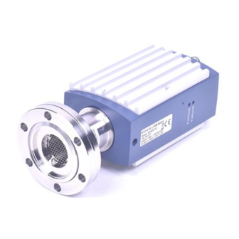
Bayard-Alpert Pirani Gauge
Dual Filament Bayard-Alpert Pirani Gauge
BPG402-S
BPG402-SD
BPG402-SE
BPG402-SL
BPG402-SP
1
tina46e1-b
(2017-12)
Table of
Contents
Previous
Page
Next
Page
1
2
3
4
5
Advertisement
Table of Contents
Need help?
Do you have a question about the BPG402-SE and is the answer not in the manual?
Ask a question
Questions and answers
Related Manuals for Inficon BPG402-SE
Measuring Instruments Inficon BPG400 Instruction Sheet
Bayard-alpert pirani gauge (6 pages)
Measuring Instruments Inficon BPG402-SD Operating Manual
Bayard-alpert pirani gauge (54 pages)
Measuring Instruments Inficon HAPSITE ER Operating Manual
Chemical identification system (432 pages)
Measuring Instruments Inficon Gemini MAG500 Operating Manual
Cold cathode (pirani) gauge (64 pages)
Measuring Instruments Inficon CDG025D2 Manual
Ethercat for capacitance diaphragm gauges (66 pages)
Measuring Instruments Inficon Porter CDG020D Operating Manual
Capacitance diaphragm gauge (28 pages)
Measuring Instruments Inficon UL1000 Fab Technical Handbook
Helium leak detector (119 pages)
Measuring Instruments Inficon Transpector SPS Operating Manual
Gas analysis system (174 pages)
Measuring Instruments Inficon Transpector MPH Operating Manual
Gas analysis system (160 pages)
Measuring Instruments Inficon Transpector XPR 3+ Operating Manual
Gas analysis system (130 pages)
Measuring Instruments Inficon PCG550 Manual
Ethercat for pirani capacitance diaphragm and pirani standard gauges (60 pages)
Measuring Instruments Inficon SKY CDG100D Operating Manual
Capacitance diaphragm gauge (44 pages)
Measuring Instruments Inficon 3000 Micro GC Operating Manual
Gas analyzer (268 pages)
Measuring Instruments Inficon Micro GC Fusion 2-Module Operating Manual
Gas analyzer (319 pages)
Measuring Instruments Inficon Gemini MAG500 Operating Manual
Cold cathode & cold cathode pirani gauge (60 pages)
Measuring Instruments Inficon PSG550 Operating Manual
Pirani standard gauge (64 pages)
This manual is also suitable for:
Bpg402-sp
Bpg402-sl
Bpg402-s
Bpg402-sd
Table of Contents
Save PDF
Print
Rename the bookmark
Delete bookmark?
Delete from my manuals?
Login
Sign In
OR
Sign in with Facebook
Sign in with Google
Upload manual
Upload from disk
Upload from URL


Need help?
Do you have a question about the BPG402-SE and is the answer not in the manual?
Questions and answers