Table of Contents
Advertisement
Quick Links
Advertisement
Table of Contents

Related Manuals for ICP DAS USA iSN-301 Series


Summary of Contents for ICP DAS USA iSN-301 Series
- Page 1 Series User Manual...
- Page 2 Names are used for identification purposes only and may be registered trademarks of their respective companies. Contact Us If you have any problems, please feel free to contact us by email at: service@icpdas.com. Ver. 1.0.0, 2023/11 iSN-301 Series User Manual 2/23...
-
Page 3: Table Of Contents
2.8 Dimensions (unit: mm) ......................11 3. Configuration via RS-485 ....................11 3.1 iSN-301 Modbus Address Mappings (Base 1) ............... 17 3.2 iSN-301 DCON Command Sets ....................19 Appendix: FAQ ........................23 Ver. 1.0.0, 2023/11 iSN-301 Series User Manual 3/23... -
Page 4: Introduction
Update time 160~6000ms, programmable Detection Field of View 27°; Diameter 0.8 meters Max. Sensor Direction Horizontal Horizontal Vertical Vertical Relay Output Signal Relay, Form A x1, SPST Type 0.25 A @ 250 VAC Ver. 1.0.0, 2023/11 iSN-301 Series User Manual 4/23... - Page 5 Parameter Parameter Target reflectance Target reflectance Target reflectance Target reflectance 16x16 16x16 16x16 16x16 White 88% Max. distance (cm) Grey 54% Grey 17% Diagonal FoV (degrees) Ranging error (mm) ±20 ±20 ±20 Ver. 1.0.0, 2023/11 iSN-301 Series User Manual 5/23...
-
Page 6: Appearance
2.2. Appearance Front Rear Ver. 1.0.0, 2023/11 iSN-301 Series User Manual 6/23... -
Page 7: Hardware Configuration
Use rotary switch positions 0 to F for node addresses 112 to 127 (default) Mode: Used to specify the operating mode DIP [4] Operating in INIT mode OFF: Operating in Normal mode (default) Ver. 1.0.0, 2023/11 iSN-301 Series User Manual 7/23... -
Page 8: Hardware Installation
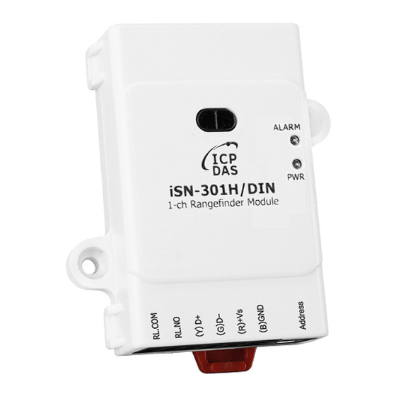
Address 2.6. Hardware Installation Installation Instructions Connector for Relay / RS-485 / Power A tip for connecting the wire to the connector A tip for removing the wire from the connector Ver. 1.0.0, 2023/11 iSN-301 Series User Manual 8/23... -
Page 9: Application
2.7. Application Minimum detectable Distance Object size Ver. 1.0.0, 2023/11 iSN-301 Series User Manual 9/23... - Page 10 Ver. 1.0.0, 2023/11 iSN-301 Series User Manual 10/23...
-
Page 11: Dimensions (Unit: Mm)
2.8 Dimensions (unit: mm) 3. Configuration via RS-485 The factory default settings for RS-485 communication Address: 1 Protocol: Modbus/RTU Baud rate: 9600 Parity: N,8,1 Response Delay (ms): 0 Ver. 1.0.0, 2023/11 iSN-301 Series User Manual 11/23... - Page 12 2. Launch the DCON_Utility_Pro.exe. Stop Search Start Search Set COM port Configuration 3. Click the icon to configure the COM port. 4. Select the COM Port number used to connect the iSN-301 logger. Ver. 1.0.0, 2023/11 iSN-301 Series User Manual 12/23...
- Page 13 5. The Baud Rate is factory default to 9600 bps. 6. Select the Protocol tab. 7. Select the Format tab and check the parity that set in the logger. 8. Click the Start Search icon. Ver. 1.0.0, 2023/11 iSN-301 Series User Manual 13/23...
- Page 14 (in the dark on a white chart) to be reached under long distance mode. Measurement Period Inter measurement period in ms, valid range 20 to 5000 It is the delay between two ranging operations. Ver. 1.0.0, 2023/11 iSN-301 Series User Manual 14/23...
- Page 15 Set ROI Range button and Show ROI Range Set or Show DO Status Set or Show DO Status Select one of the radio button and the checkbox next to DO will display the setting for selected item. Ver. 1.0.0, 2023/11 iSN-301 Series User Manual 15/23...
- Page 16 After complete setting, set the pin 4.INIT back to OFF position and power cycle the logger again to take the setting effect. Ver. 1.0.0, 2023/11 iSN-301 Series User Manual 16/23...
-
Page 17: Isn-301 Modbus Address Mappings (Base 1)
Distance offset in mm 40481 Firmware version (low word) 40482 Firmware version (high word) 40483 Module name (low word), 0x0301 40484 Module name (high word), 0x534E 40485 RS-485 module address, 1 to 247 Ver. 1.0.0, 2023/11 iSN-301 Series User Manual 17/23... - Page 18 Reset status, 1: first read after powered on, 0: not the first read after powered on 00280 Write 1 to clear all high latched input values 00281 Write 1 to clear all low latched input values 00289 Low alarm status of distance measurement. Ver. 1.0.0, 2023/11 iSN-301 Series User Manual 18/23...
-
Page 19: Isn-301 Dcon Command Sets
$AA5 read reset status !AA1 first after power on, !AA0 others Read All Analog Inputs response > (distance in mm) #AAN Read Channel Analog Input N = 0 for distance in mm Ver. 1.0.0, 2023/11 iSN-301 Series User Manual 19/23... - Page 20 33ms is the minimum timing budget which can work for all distance modes. 140ms is the timing budget which allows the maximum distance of 4 m (in the dark on a white chart) to be reached under long distance mode. Ver. 1.0.0, 2023/11 iSN-301 Series User Manual 20/23...
- Page 21 @AALO(data)CN Set low alarm limit of an AI channel, N = 0 for distance measurement Command Description @AARACN Read AI alarm enabled/disabled status of a channel response !AAN, N->0: disabled, 1: momentary, 2: latched @AARAL Read AI alarm status and clear latched alarm status response !AAHHLL Ver. 1.0.0, 2023/11 iSN-301 Series User Manual 21/23...
- Page 22 S-> 0 ~ 1: safe value in hex format ~AARD read response delay time in ms in hex format ~AARDVV set response delay time in ms, VV in hex format, 00 - 1E Ver. 1.0.0, 2023/11 iSN-301 Series User Manual 22/23...
- Page 23 0: checksum disabled 1: checksum enabled Base Address: 96 (0x60) DIP Switch Off: Modbus RTU, On: DCON Off: hardware configuration, On: software configuration On: rotary switch address added by 16 On: INIT Appendix: FAQ Ver. 1.0.0, 2023/11 iSN-301 Series User Manual 23/23...
Need help?
Do you have a question about the iSN-301 Series and is the answer not in the manual?
Questions and answers