Table of Contents
Advertisement
Quick Links
I-7000 New Features
1. Self Tuner Inside
2. Multiple Baud Rate
3. Multiple Data Format
4. Dual WatchDog Inside
5. True Distributed Control
6. High Speed & High
Density I/O
Warranty
All products manufactured by ICP DAS are warranted
against defective materials for a period of one year from the date
of delivery to the original purchaser.
Warning
ICP DAS assume no liability for damages consequent to the
use of this product. ICP DAS reserves the right to change this
manual at any time without notice. The information furnished by
ICP DAS is believed to be accurate and reliable. However, no
responsibility is assumed by ICP DAS for its use, nor for any
infringements of patents or other rights of third parties resulting
from its use.
Copyright
Copyright 1998 by ICP DAS. All rights are reserved.
Trademark
The names used for identification only maybe registered
trademarks of their respective companies.
I-7080, I-7080D, I-7080B, I7080BD User Manual (V 2.2) ------------------ 1
I-7080, I-7080B
User Manual
Your Powerful Tools
Create New Ideas
Create New Applications
Advertisement
Table of Contents

Subscribe to Our Youtube Channel
Related Manuals for ICP DAS USA I-7080


Summary of Contents for ICP DAS USA I-7080
- Page 1 Copyright Copyright 1998 by ICP DAS. All rights are reserved. Trademark The names used for identification only maybe registered trademarks of their respective companies. I-7080, I-7080D, I-7080B, I7080BD User Manual (V 2.2) ------------------ 1...
-
Page 2: Table Of Contents
$AA1L..........................40 2.17 $AA1L( ) ........................41 DATA 2.18 $AA2 ............................42 2.19 $AA3N ..........................43 2.20 $AA3N( )........................44 DATA 2.21 $AA4 ...........................45 2.22 $AA4S..........................46 2.23 $AA5N ..........................47 2.24 $AA5NS ..........................48 2.25 $AA6N ..........................49 I-7080, I-7080D, I-7080B, I7080BD User Manual (V 2.2) ------------------ 2... - Page 3 DATA 2.50 @AARP..........................74 2.51 @AARP..........................75 2.52 @AARA..........................76 2.53 @AARP..........................77 OPERATIONS PRINCIPLE & APPLICATION NOTES............78 INIT*_ ....................78 PERATION RINCIPLE 3.2 D/O O .......................79 PERATION RINCIPLE 3.3 New Features of 7080B …………………………………………………….80 I-7080, I-7080D, I-7080B, I7080BD User Manual (V 2.2) ------------------ 3...
-
Page 4: Introduction
100K Hz The I-7080D is the I-7080 with a 5-digit LED display. The counter value and input signal frequency can be shown in LED directly without PC control. The I-7080B will save the counter value to EEPROM when the power goes off. - Page 5 High alarm on counter 0 & 1 Counter preset value: 0 Module name: 7080 default setting of I-7080D: High/High-High alarm on counter 0 Counter preset value: 0 Module name: 7080D I-7080, I-7080D, I-7080B, I7080BD User Manual (V 2.2) ------------------ 5...
- Page 6 Channel 0 is non-isolated & channel 0 is isolated (input mode 2, $AAB2) Channel 0 is isolated & channel 1 is non-isolated (input mode 3, $AAB3) Input frequency 50K max. 50K max. I-7080, I-7080D, I-7080B, I7080BD User Manual (V 2.2) ------------------ 6...
-
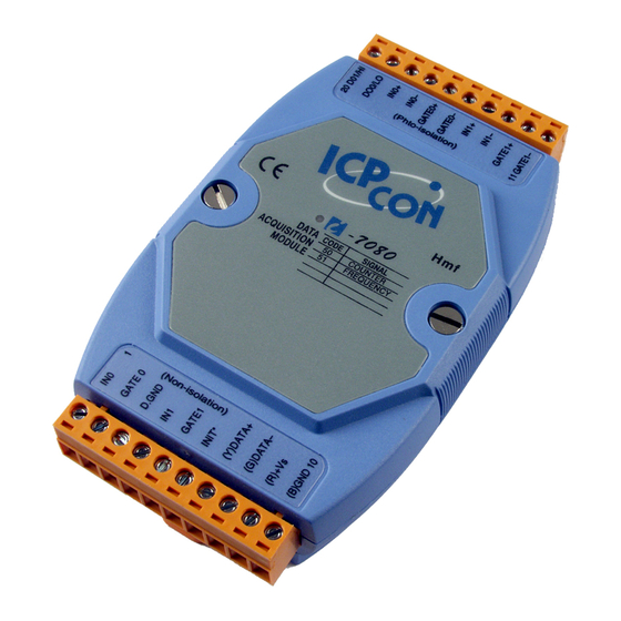
Page 7: Pin Assignment
Pin Assignment Isolated Input Non-isolated Input I-7080, I-7080D, I-7080B, I7080BD User Manual (V 2.2) ------------------ 7... -
Page 8: Specifications
2 channels, open-collector to 30V, 30mA max. load Power dissipation: 300mW Power Power requirements: I-7080/7080D: +10V to 30V(non-regulated) I-7080B/7080BD: +24V to 30V(non-regulated) Power consumption : 2W for I-7080, 2.2W for I-7080D I-7080, I-7080D, I-7080B, I7080BD User Manual (V 2.2) ------------------ 8... -
Page 9: Block Diagram
In1- Isolated/Non-isolated input selection Gate0+ Isolated/Non-isolated gate selection Gate0- Programmable threshold voltage Gate1+ Gate1- Isolated input Gate0(TTL) Voltage Gate1(TTL) Detect In0(TTL) In1(TTL) Save to Non-isolated input EEPROM For 7080B/7080BD only I-7080, I-7080D, I-7080B, I7080BD User Manual (V 2.2) ------------------ 9... -
Page 10: Application Wiring
If the external load is resistive load, the 1N4001 can be omitted. (transistor, lamp, resistor, …) If the external load is inductive load, the 1N4001 can’t be omitted. (relay, coil, …) I-7080, I-7080D, I-7080B, I7080BD User Manual (V 2.2) ------------------ 10... - Page 11 RS-485 Data- Data- In1+ RS-485 Data- Init* Gate0- Counter-0 Counter-1 & Gate1 & Gate-0 Gate0+ Gate-1 (isolated) In0- (non-iolated) D.Gnd In0+ Counter-0 & Do0/Lo Gate0 Gate-0 Do1/Hi (non-iolated) I-7018 & I-7018D I-7080, I-7080D, I-7080B, I7080BD User Manual (V 2.2) ------------------ 11...
-
Page 12: Quick Start
11: frequency measurement of channel-1 Note: the command $01B1(step 7) can be used to select the iso- lated input.(the command $01B2 and $01B3 are used for the other selections) I-7080, I-7080D, I-7080B, I7080BD User Manual (V 2.2) ------------------ 12... - Page 13 9: counter measurement of channel-1 Note: the command $01B1(step 7) can be used to select the iso- lated input.(the command $01B2 and $01B3 are used for the other selections) I-7080, I-7080D, I-7080B, I7080BD User Manual (V 2.2) ------------------ 13...
-
Page 14: Default Setting
The counter/frequency input can be selected from isolated or non-isolated signal. The channel 0 & channel 1 can be selected separately. There are 4 different input mode given as following: These four input modes can be used in both of I-7080 & I-7080D. Input Mode... - Page 15 There are no alarm function in frequency mode(51). There are two counter alarm mode, alarm mode 0 & alarm mode 1. These two alarm modes can be used in both of I-7080 & I- 7080D. The alarm mode 0 is designed for two-channel application...
- Page 16 The high trigger level can be changed by $AA1H(data) command, the low trigger can be changed by $AA1L(data) comand. The high trigger level must be greater than the low trigger level. I-7080, I-7080D, I-7080B, I7080BD User Manual (V 2.2) ------------------ 16...
- Page 17 900 us. Therefore all noise below 900 us will be filtered out by the digital filter. These steps are given as following: 1. $AAB0 2. $AA0H00900 3. $AA0L00900 4. $AA41 I-7080, I-7080D, I-7080B, I7080BD User Manual (V 2.2) ------------------ 17...
- Page 18 Factory default setting Counter preset value is 0 Power on state Counter 0/1 go to preset value $AA6N Counter N go to preset value $AAPN(data) Set preset value of counter N I-7080, I-7080D, I-7080B, I7080BD User Manual (V 2.2) ------------------ 18...
- Page 19 • #AA? perform frequency measurement The status-read-back commands are given as following: • $AAB mode read back • $AA1H high_level threshold value read back • $AA1L(data) low_level threshold value read back I-7080, I-7080D, I-7080B, I7080BD User Manual (V 2.2) ------------------ 19...
- Page 20 3 Isolated channel 0 Non-isolated channel $AA1H(data) & 1 & threshold value $AA1L(data) active Note: the threshold value command, $AA1H(data) & $AA1L(data) are effective to Non-isolated input only. I-7080, I-7080D, I-7080B, I7080BD User Manual (V 2.2) ------------------ 20...
-
Page 21: Tables
115200 BPS Configuration Code : FF, 2-char (for all) 0 checksum frequency gate time 0=disable 0: 0.1 second 1=enable 1: 1.0 second Configuration Code Table: TT Input Range Counter Frequency I-7080, I-7080D, I-7080B, I7080BD User Manual (V 2.2) ------------------ 21... -
Page 22: Command Set
$AA1H !AA(data) Read high trigger level Sec. 2.14 $AA1H(data) Set high trigger level Sec. 2.15 $AA1L !AA(data) Read low trigger level Sec. 2.16 $AA1L(data) Set low trigger level Sec. 2.17 I-7080, I-7080D, I-7080B, I7080BD User Manual (V 2.2) ------------------ 22... - Page 23 Sec. 2.33 @AADI !AAS0D00 Read D/O & alarm state Sec. 2.37 @AADO0D Set D/O value Sec. 2.38 @AAGN !AA(data) Read preset value Sec. 2.44 @AAPN(data) Set preset value Sec. 2.45 I-7080, I-7080D, I-7080B, I7080BD User Manual (V 2.2) ------------------ 23...
- Page 24 Sec. 2.51 @AARA Read Hi-Hi-alarm value Sec. 2.53 LED Command Set $AA8 !AAS Read LED configuration Sec. 2.27 $AA8V Set LED configuration Sec. 2.28 $AA9(data) Send data to LED Sec. 2.29 I-7080, I-7080D, I-7080B, I7080BD User Manual (V 2.2) ------------------ 24...
-
Page 25: Aannttccff
Change to frequency mode response : !02(cr) Refer to “I-7000 Bus Converter User Manual” chapter-5 for the following functions: module status unknown(Sec. 5.1), change address(Sec. 5.2) change baud rate(Sec. 5.3), checksum enable/disable(Sec. 5.4) I-7080, I-7080D, I-7080B, I7080BD User Manual (V 2.2) ------------------ 25... -
Page 26: Aan
$012(cr) Counter-0=0x1E=30 (in response : !01500600(cr) decimal) command: #010(cr) response : >0000001E(cr) command: $022(cr) Frequency-1=0x1E Hz = 30 response : !02510600(cr) Hz (in decimal) command: #021(cr) response : >0000001E(cr) I-7080, I-7080D, I-7080B, I7080BD User Manual (V 2.2) ------------------ 26... - Page 27 : Host send this command to tell all modules “Host is Description OK”. : ~**[chk](cr) Syntax ~ is a delimiter character [chk]=2-character checksum, if checksum disable no [chk] (cr)=0x0D : no response Response Example command: ~**(cr) response : No Response I-7080, I-7080D, I-7080B, I7080BD User Manual (V 2.2) ------------------ 27...
- Page 28 [chk]=2-character checksum, if checksum disable no [chk] (cr)=0x0D Example command: ~010(cr) Status of module 01 is OK response : !0100(cr) Module status=04 host watchdog command: ~020(cr) failure HOST is down now response : !0204(cr) I-7080, I-7080D, I-7080B, I7080BD User Manual (V 2.2) ------------------ 28...
- Page 29 Output command is ignored response : !(cr) command: ~011(cr) clear module status response : !01(cr) command: ~010(cr) module status=0x00 response : !0100(cr) command: @01DO00(cr) Output command is OK response : >(cr ) I-7080, I-7080D, I-7080B, I7080BD User Manual (V 2.2) ------------------ 29...
- Page 30 Host watchdog timer of module 01 is disable command: ~012(cr) response : !01000(cr) host watchdog timer of command: ~022(cr) module 02 is enable and = response : !0210A(cr) 0.1*10 = 1 second. I-7080, I-7080D, I-7080B, I7080BD User Manual (V 2.2) ------------------ 30...
-
Page 31: Aa3Ett
~013000(cr) of module 01 response : !01(cr) command: ~02310A(cr) host watchdog timer of response : !02(cr) module 02 is enable and = 0.1*10 = 1 second. I-7080, I-7080D, I-7080B, I7080BD User Manual (V 2.2) ------------------ 31... -
Page 32: Aaas
? is a delimiter character indicating a invalid command AA=2-character HEX module address [chk]=2-character checksum, if checksum disable no [chk] (cr)=0x0D Example command: ~01A0(cr) Set alarm mode=0. response : !01(cr) command: ~02A1(cr) Set alarm mode=1. response : !02(cr) I-7080, I-7080D, I-7080B, I7080BD User Manual (V 2.2) ------------------ 32... -
Page 33: Aao(Name)
: !017080D(cr) 7080D to 8080D command: ~01O8080D(cr) response : !01(cr) Note: This command is designed for OEM/ODM user. The user can use it to change the module name for other purpose. I-7080, I-7080D, I-7080B, I7080BD User Manual (V 2.2) ------------------ 33... -
Page 34: Aa0H
[chk]=2-character checksum, if checksum disable no [chk] (cr)=0x0D Example command: $010H(cr) Min. width = 10 uS response : !0100010(cr) command: $020H(cr) Min. width = 1000 uS = 1 mS response : !0201000(cr) I-7080, I-7080D, I-7080B, I7080BD User Manual (V 2.2) ------------------ 34... -
Page 35: Aa0H( Data )
[chk]=2-character checksum, if checksum disable no [chk] (cr)=0x0D Example command: $010H00010(cr) Min. width = 10 uS response : !01(cr) command: $020H01000(cr) Min. width = 1000 uS = 1 mS response : !02(cr) I-7080, I-7080D, I-7080B, I7080BD User Manual (V 2.2) ------------------ 35... -
Page 36: Aa0L
2 uS to 65535 uS. [chk]=2-character checksum, if checksum disable no [chk] (cr)=0x0D Example command: $010H(cr) Min. width=20 uS response : !0100020(cr) command: $020H(cr) Min. width=2000 uS=2 mS response : !0202000(cr) I-7080, I-7080D, I-7080B, I7080BD User Manual (V 2.2) ------------------ 36... -
Page 37: Aa0L( Data )
[chk]=2-character checksum, if checksum disable no [chk] (cr)=0x0D Example command: $010H00020(cr) Min. width = 20 uS response : !01(cr) command: $020H02000(cr) Min. width = 2000 uS = 2 mS response : !02(cr) I-7080, I-7080D, I-7080B, I7080BD User Manual (V 2.2) ------------------ 37... -
Page 38: Aa1H
0.1 volt and the range can be from 0.0 to 5.0 volt. [chk]=2-character checksum, if checksum disable no [chk] (cr)=0x0D Example command: $011H(cr) High trigger level=2.4 volt response : !0124(cr) command: $021H(cr) High trigger level=3.0 volt response : !0230(cr) I-7080, I-7080D, I-7080B, I7080BD User Manual (V 2.2) ------------------ 38... -
Page 39: Aa1H( Data )
[chk]=2-character checksum, if checksum disable no [chk] (cr)=0x0D Example command: $011H24(cr) High trigger level=2.4 volt response : !01(cr) command: $021H30(cr) High trigger level=3.0 volt response : !02(cr) : default is 2.4V Note I-7080, I-7080D, I-7080B, I7080BD User Manual (V 2.2) ------------------ 39... -
Page 40: Aa1L
0.1 volt and the range can be from 0.0 to 5.0 volt. [chk]=2-character checksum, if checksum disable no [chk] (cr)=0x0D Example command: $011L(cr) Low trigger level=0.8 volt response : !0108(cr) command: $021L(cr) Low trigger level=1.0 volt response : !0210(cr) I-7080, I-7080D, I-7080B, I7080BD User Manual (V 2.2) ------------------ 40... -
Page 41: Aa1L( Data )
[chk]=2-character checksum, if checksum disable no [chk] (cr)=0x0D Example command: $011L08(cr) Low trigger level=0.8 volt response : !01(cr) command: $021L10(cr) Low trigger level=1.0 volt response : !02(cr) : default is 0.8V Note I-7080, I-7080D, I-7080B, I7080BD User Manual (V 2.2) ------------------ 41... - Page 42 100,000 times max. Therefore the user should not change configuration code often for testing. The $AA2 command is used to read EEPROM data only, therefore the user can send this command to I-7000 module infinitely. I-7080, I-7080D, I-7080B, I7080BD User Manual (V 2.2) ------------------ 42...
-
Page 43: Aa3N
[chk]=2-character checksum, if checksum disable no [chk] (cr)=0x0D Example command: $0130(cr) Counter-0 from preset value response : !010000FFFF(cr) to FFFF command: $0131(cr) Counter-1 from preset value response : !01FFFFFFFF(cr) to FFFFFFFF I-7080, I-7080D, I-7080B, I7080BD User Manual (V 2.2) ------------------ 43... -
Page 44: Aa3N( Data )
[chk]=2-character checksum, if checksum disable no [chk] (cr)=0x0D Example command: $01300000FFFF(cr) Counter-0 from preset value response : !01(cr) to FFFF command: $0131FFFFFFFF(cr) Counter-1 from preset value response : !01(cr) to FFFFFFFF I-7080, I-7080D, I-7080B, I7080BD User Manual (V 2.2) ------------------ 44... - Page 45 [chk]=2-character checksum, if checksum disable no [chk] (cr)=0x0D Example command: $014(cr) Digital filter is disable. response : !010(cr) Digital filter is enable. command: $024(cr) response : !021(cr) I-7080, I-7080D, I-7080B, I7080BD User Manual (V 2.2) ------------------ 45...
-
Page 46: Aa4S
AA=2-character HEX module address [chk]=2-character checksum, if checksum disable no [chk] (cr)=0x0D Example command: $0140(cr) Digital filter is disable. response : !01(cr) Digital filter is enable. command: $0241(cr) response : !02(cr) I-7080, I-7080D, I-7080B, I7080BD User Manual (V 2.2) ------------------ 46... -
Page 47: Aa5N
(enable) [chk]=2-character checksum, if checksum disable no [chk] (cr)=0x0D Example command: $0150(cr) Counter 0 is stop now. response : !010(cr) Counter 1 is start now. command: $0151(cr) response : !011(cr) I-7080, I-7080D, I-7080B, I7080BD User Manual (V 2.2) ------------------ 47... -
Page 48: Aa5Ns
AA=2-character HEX module address [chk]=2-character checksum, if checksum disable no [chk] (cr)=0x0D Example command: $01500(cr) Stop the counter 0. response : !01(cr) Start the counter 1. command: $01511(cr) response : !01(cr) I-7080, I-7080D, I-7080B, I7080BD User Manual (V 2.2) ------------------ 48... -
Page 49: Aa6N
Reset counter 0 to preset value command: $0160(cr) response : !01(cr) command: @01G1(cr) Preset value=0xABCD response : !010000ABCD(cr) Reset counter 1 to preset value command: $0161(cr) 0xABCD response : !01(cr) I-7080, I-7080D, I-7080B, I7080BD User Manual (V 2.2) ------------------ 49... -
Page 50: Aa7N
[chk] (cr)=0x0D Example command: $0170(cr) Counter 0 is overflow. response : !011(cr) command: $0160(cr) Clear the overflow flag. response : !01(cr) Counter 1 is OK. command: $0171(cr) response : !010(cr) I-7080, I-7080D, I-7080B, I7080BD User Manual (V 2.2) ------------------ 50... - Page 51 LED show the value of channel 0. response : !010(cr) command: $028(cr) LED show the value of channel 1. response : !021(cr) command: $038(cr) HOST control the LED display. response : !032 (cr) I-7080, I-7080D, I-7080B, I7080BD User Manual (V 2.2) ------------------ 51...
-
Page 52: Aa8V
[chk]=2-character checksum, if checksum disable no [chk] (cr)=0x0D Example: command: $0181(cr) LED shows channel 1. response : !01(cr) command: $0282(cr) HOST will control LED. response : !02(cr) command: $029040.00(cr) response : !02(cr) I-7080, I-7080D, I-7080B, I7080BD User Manual (V 2.2) ------------------ 52... -
Page 53: Aa9(Data)
[chk] (cr)=0x0D Example: command: $01999999.(cr) Show max. = 99999. response : !01(cr) command: $0290.0000(cr) Show min. = 0.0000. response : !02(cr) command: $03912.345(cr) Show display = 12.345 response : !03(cr) I-7080, I-7080D, I-7080B, I7080BD User Manual (V 2.2) ------------------ 53... -
Page 54: Aaa
Example command: $01A(cr) Gate is low active. response : !010(cr) command: $02A(cr) Gate is high active. response : !021(cr) command: $03A(cr) Gate is disable (always active). response : !032 (cr) I-7080, I-7080D, I-7080B, I7080BD User Manual (V 2.2) ------------------ 54... -
Page 55: Aaag
(cr)=0x0D Example command: $01A0(cr) Gate is low active. response : !01(cr) command: $02A1(cr) Gate is high active. response : !02(cr) command: $03A2(cr) Gate is disable (always active). response : !03(cr) I-7080, I-7080D, I-7080B, I7080BD User Manual (V 2.2) ------------------ 55... -
Page 56: Aab
1 is non-isolated. command: $02B(cr) Counter/frequency channel 0 is response : !021(cr) isolated, channel 1 is isolated. command: $03B(cr) Counter/frequency channel 0 is non- response : !032(cr) isolated, channel 1 is isolated. I-7080, I-7080D, I-7080B, I7080BD User Manual (V 2.2) ------------------ 56... -
Page 57: Aabs
1 is non-isolated. command: $02B1(cr) Counter/frequency channel 0 is response : !02(cr) isolated, channel 1 is isolated. command: $03B2(cr) Counter/frequency channel 0 is non- response : !03(cr) isolated, channel 1 is isolated. I-7080, I-7080D, I-7080B, I7080BD User Manual (V 2.2) ------------------ 57... -
Page 58: Aaf
AA=2-character HEX module address data=5-character for version number [chk]=2-character checksum, if checksum disable no [chk] (cr)=0x0D Example command: $01F(cr) Ver. A2.0 response : !01A2.0(cr) command: $02F(cr) Ver. A3.0 response : !02A3.0(cr) I-7080, I-7080D, I-7080B, I7080BD User Manual (V 2.2) ------------------ 58... -
Page 59: Aai
[chk]=2-character checksum, if checksum disable no [chk] (cr)=0x0D Example command: $01I(cr) INIT* pin is connected to GND pin. response : !010(cr) command: $02I(cr) INIT* pin is open. response : !021(cr) I-7080, I-7080D, I-7080B, I7080BD User Manual (V 2.2) ------------------ 59... -
Page 60: Aam
[chk]=2-character checksum, if checksum disable no [chk] (cr)=0x0D Example command: $01M(cr) Module name of 01 is 7080 response : !017080(cr) command: $02M(cr) Module name of 02 is 7080D response : !027080D(cr) I-7080, I-7080D, I-7080B, I7080BD User Manual (V 2.2) ------------------ 60... -
Page 61: Aadi
0 alarm=enable & LATCH mode [chk]=2-character checksum, if checksum disable no [chk] (cr)=0x0D Example command: @01DI(cr) Alarm disable. response : !0100000(cr) D/O0=D/O1=OFF command: @02DI(cr) Alarm enable. D/O0=ON. response : !0230100(cr) D/O1=OFF I-7080, I-7080D, I-7080B, I7080BD User Manual (V 2.2) ------------------ 61... -
Page 62: Aado0D
NOTE: if the alarm is enable, the D/O 0 & D/O 1 will be always controlled by module. Therefore the following D/O commands will be ignored. power-on value is changed to hi/lo condition immediately the @AADO0D command is ignored. I-7080, I-7080D, I-7080B, I7080BD User Manual (V 2.2) ------------------ 62... -
Page 63: Aaean
? is a delimiter character indicating a invalid command AA=2-character HEX module address [chk]=2-character checksum, if checksum disable no [chk] (cr)=0x0D Example command: @01EA0(cr) Enable counter 0. response : !01(cr) command: @01EA1(cr) Enable counter 1. response : !02(cr) I-7080, I-7080D, I-7080B, I7080BD User Manual (V 2.2) ------------------ 63... -
Page 64: Aaeat
NOTE: if the alarm is enable, the D/O 0 & D/O 1 will be always controlled by module. Therefore the following D/O commands will be ignored. power-on value is changed to hi/lo condition immediately the @AADO0D command is ignored. I-7080, I-7080D, I-7080B, I7080BD User Manual (V 2.2) ------------------ 64... -
Page 65: Aaca
? is a delimiter character indicating a invalid command AA=2-character HEX module address [chk]=2-character checksum, if checksum disable no [chk] (cr)=0x0D Example command: @01CA(cr) Clear latch alarm. response : !01(cr) command: @02CA(cr) Clear latch alarm. response : !02(cr) I-7080, I-7080D, I-7080B, I7080BD User Manual (V 2.2) ------------------ 65... -
Page 66: Aada
? is a delimiter character indicating a invalid command AA=2-character HEX module address [chk]=2-character checksum, if checksum disable no [chk] (cr)=0x0D Example command: @01DA(cr) Disable alarm. response : !01(cr) command: @02DA(cr) Disable alarm. response : !02(cr) I-7080, I-7080D, I-7080B, I7080BD User Manual (V 2.2) ------------------ 66... -
Page 67: Aadan
AA=2-character HEX module address [chk]=2-character checksum, if checksum disable no [chk] (cr)=0x0D Example command: @01DA0(cr) Disable counter 0 alarm. response : !01(cr) command: @02DA1(cr) Disable counter 1 alarm. response : !02(cr) I-7080, I-7080D, I-7080B, I7080BD User Manual (V 2.2) ------------------ 67... -
Page 68: Aagn
[chk] (cr)=0x0D Example command: @01G0(cr) The preset value of counter 0 response : !010000FFFF(cr) is 0000FFFF. command: @02G1(cr) The preset value of counter 1 response : !0200000000(cr) is 00000000. I-7080, I-7080D, I-7080B, I7080BD User Manual (V 2.2) ------------------ 68... -
Page 69: Aapn(Data)
[chk] (cr)=0x0D Example command: @01P0FFFF0000(cr) The preset value of counter response : !01(cr) 0 is FFFF0000. command: @02P10000FFFF(cr) The preset value of counter response : !02(cr) 1 is 0000FFFF. I-7080, I-7080D, I-7080B, I7080BD User Manual (V 2.2) ------------------ 69... -
Page 70: Aapa(Data)
[chk] (cr)=0x0D Example command: @01PAFFFF0000(cr) The alarm limit of counter- response : !01(cr) 0 is FFFF0000. command: @02PA0000FFFF(cr) The alarm limit of counter 0 response : !02(cr) is 0000FFFF. I-7080, I-7080D, I-7080B, I7080BD User Manual (V 2.2) ------------------ 70... -
Page 71: Aapa(Data)
[chk] (cr)=0x0D Example command: @01PAFFFF0000(cr) The Hi-alarm limit of response : !01(cr) counter 0 is FFFF0000. command: @02PA0000FFFF(cr) The Hi-alarm limit of response : !02(cr) counter 0 is 0000FFFF. I-7080, I-7080D, I-7080B, I7080BD User Manual (V 2.2) ------------------ 71... -
Page 72: Aasa(Data)
[chk] (cr)=0x0D Example command: @01SAFFFF0000(cr) The alarm limit of counter 1 response : !01(cr) is FFFF0000. command: @02SA0000FFFF(cr) The alarm limit of counter 1 response : !02(cr) is 0000FFFF. I-7080, I-7080D, I-7080B, I7080BD User Manual (V 2.2) ------------------ 72... -
Page 73: Aasa(Data)
[chk] (cr)=0x0D Example command: @01SAFFFF0000(cr) The Hi-Hi-alarm limit of response : !01(cr) counter 0 is FFFF0000. command: @02SA0000FFFF(cr) The Hi-Hi-alarm limit of response : !02(cr) counter 0 is 0000FFFF. I-7080, I-7080D, I-7080B, I7080BD User Manual (V 2.2) ------------------ 73... -
Page 74: Aarp
[chk] (cr)=0x0D Example command: @01RP(cr) The alarm limit of counter 0 response : !01FFFF0000(cr) is FFFF0000. command: @02RP(cr) The alarm limit of counter 0 response : !020000FFFF(cr) is 0000FFFF. I-7080, I-7080D, I-7080B, I7080BD User Manual (V 2.2) ------------------ 74... -
Page 75: Aarp
[chk] (cr)=0x0D Example command: @01RP(cr) The Hi-alarm limit of response : !01FFFF0000(cr) counter 0 is FFFF0000. command: @02RP(cr) The Hi-alarm limit of response : !020000FFFF(cr) counter 0 is 0000FFFF. I-7080, I-7080D, I-7080B, I7080BD User Manual (V 2.2) ------------------ 75... -
Page 76: Aara
[chk] (cr)=0x0D Example command: @01RA(cr) The alarm limit of counter 1 response : !01FFFF0000(cr) is FFFF0000. command: @02RA(cr) The alarm limit of counter 1 response : !020000FFFF(cr) is 0000FFFF. I-7080, I-7080D, I-7080B, I7080BD User Manual (V 2.2) ------------------ 76... -
Page 77: Aarp
[chk] (cr)=0x0D Example command: @01RP(cr) The Hi-Hi-alarm limit of response : !01FFFF0000(cr) counter 0 is FFFF0000. command: @02RP(cr) The Hi-Hi-alarm limit of response : !020000FFFF(cr) counter 0 is 0000FFFF. I-7080, I-7080D, I-7080B, I7080BD User Manual (V 2.2) ------------------ 77... -
Page 78: Operations Principle & Application Notes
Step 4: record the EEPROM data of this I-7000 module Step 5: power off and disconnect INIT*_pin and GND_pin Step 6: power on Refer to “I-7000 Bus Converter User Manual” Sec. 5.1 for more information. I-7080, I-7080D, I-7080B, I7080BD User Manual (V 2.2) ------------------ 78... -
Page 79: D/O Operation Principle
D/O Operation Principle Refer to Sec. 1.8.3 for more information. The D/O output of I-7080 & I-7080D modules will be turn OFF after first power on. The D/O output will be changed to the desired state if the “@AADO” command is received. Then all these D/O will keep in the same states until next “@AADO”... -
Page 80: New Features Of 7080B
EEPROM, but the current counter is no changed. 3. Assume 7080B is set to type 52, @AAPN (data) command will set the current counter value & preset value in EEPROM at the same time. I-7080, I-7080D, I-7080B, I7080BD User Manual (V 2.2) ------------------ 80...
Need help?
Do you have a question about the I-7080 and is the answer not in the manual?
Questions and answers