
Related Manuals for Freescale Semiconductor metrowerks CodeWarrior


Summary of Contents for Freescale Semiconductor metrowerks CodeWarrior
- Page 1 CodeWarrior™ USB TAP Users Guide A Freescale Semiconductor Company Revised 10 March 2005...
- Page 2 Metrowerks, and the Metrowerks logo are registered trademarks of Metrowerks Corporation in the United States and/ or other countries. CodeWarrior is a trademark or registered trademark of Metrowerks Corporation in the United States and/or other countries. All other trade names and trademarks are the property of their respective owners. Copyright ©...
-
Page 3: Table Of Contents
Table of Contents 1 Introducing the CodeWarrior™ USB TAP Emulator What is the USB TAP Emulator? ..... 5 Product Highlights ......6 The Debugging Environment . - Page 4 Table of Contents 4 Hardware Specifications Connectors and LEDs ......21 Run/Pause Indicator ......22 Transmit/Receive Indicator .
-
Page 5: Introducing The Codewarrior™ Usb Tap Emulator
Introducing the CodeWarrior™ USB TAP Emulator The CodeWarrior USB TAP emulator is a cost-effective tool that helps you develop and debug a number of processors and microcontrollers. This chapter introduces you to the USB TAP emulator. The sections are: • What is the USB TAP Emulator? •... -
Page 6: Product Highlights
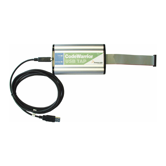
Introducing the CodeWarrior™ USB TAP Emulator What is the USB TAP Emulator? Figure 1.1 USB TAP for ARM®JTAG with USB 2.0 Cable Product Highlights The USB TAP emulator has these features: • Supports the following systems: PowerPC™ processors, ARM® processors, ColdFire™... -
Page 7: The Debugging Environment
Introducing the CodeWarrior™ USB TAP Emulator What is the USB TAP Emulator? • Software debug capabilities including: – Controlling instruction execution. – Display and modify target memory. – Examine and modify any processor registers. – Run to breakpoints in ROM, RAM, or flash memory. –... -
Page 8: Operating Requirements
Introducing the CodeWarrior™ USB TAP Emulator Operating Requirements Operating Requirements Before setting up your system, you should make sure that the operating environment is prepared. Standard Electrostatic Precautions This instrument contains static-sensitive components that are subject to damage from electrostatic discharge. Use standard ESD precautions when transporting, handling, or using the instrument and the target, when connecting/disconnecting the instrument and the target, and when removing the cover of the instrument. -
Page 9: Target Requirements
Introducing the CodeWarrior™ USB TAP Emulator Related Documentation Target Requirements The USB TAP emulator automatically supports target signal levels from 1.8V to 3.3V. NOTE In the case of the PowerPC, for the USB TAP emulator to properly stop and restart a JTAG/COP target processor, the QACK signal must be pulled low. - Page 10 Introducing the CodeWarrior™ USB TAP Emulator Related Documentation USB TAP Users Guide...
-
Page 11: Setting Up The Usb Tap Emulator
Setting up the USB TAP Emulator This chapter explains how to set up the USB TAP emulator. The sections are: • Unpacking the USB TAP Emulator • Identifying the Components • Installing the CodeWarrior USB TAP Device Drivers • Connecting to the Target and your Host Computer •... -
Page 12: Identifying The Components
Setting up the USB TAP Emulator Identifying the Components Identifying the Components Before you begin, check that these components are present: • USB TAP emulator. • One USB 2.0 cable for connecting the USB TAP to your host computer. Installing the CodeWarrior USB TAP Device Drivers NOTE If you are using the USB TAP emulator with a PC running... - Page 13 Setting up the USB TAP Emulator Installing the CodeWarrior USB TAP Device Drivers Figure 2.1 Found New Hardware Wizard NOTE If you receive the message “unknown device,” this means that either the USB TAP device driver was not installed properly or that there is a problem with either the USB port or the USB TAP device.
-
Page 14: Connecting To The Target And Your Host Computer
Setting up the USB TAP Emulator Connecting to the Target and your Host Computer Connecting to the Target and your Host Computer To test your software using the USB TAP emulator, you must have working target hardware. This section explains how to connect the USB TAP emulator to such hardware and to your host computer. -
Page 15: Target Connection
Setting up the USB TAP Emulator Connecting to the Target and your Host Computer Target Connection CAUTION Failure to properly connect the USB TAP emulator to the target may damage the USB TAP emulator or target. Verify all connections before applying power. If your target system has a debug port header, you can directly connect the USB TAP emulator to the target debug port header. -
Page 16: Setting The Debug Port Clock Frequency
Setting up the USB TAP Emulator Connecting to the Target and your Host Computer 5. Reconnect the USB cable to the USB TAP emulator. 6. Apply power to your target. NOTE If you are using the USB TAP emulator with a PC running Windows®... -
Page 17: What To Do Next
Setting up the USB TAP Emulator What To Do Next NOTE If you plug the USB 2.0 Cable into an USB 1.1 port, you will get a warning in a Windows pop-up dialog box and the performance of the USB TAP will be slower. Please disregard this warning if you only have an USB 1.1 port. - Page 18 Setting up the USB TAP Emulator What To Do Next USB TAP Users Guide...
-
Page 19: Using The Usb Tap
Using the USB TAP This chapter provides system startup procedures, explains how the USB TAP works and provides important information about using the system. The sections are: • USB TAP System Startup • Notes on Using the USB TAP USB TAP System Startup This section explains how to start using the USB TAP and the debugger. -
Page 20: Run/Pause/Mixed Mode States
Using the USB TAP USB TAP System Startup These topics provide information specific to USB TAP operation: • Run/Pause/Mixed Mode States • Breakpoints in Exception/Interrupt Handlers Run/Pause/Mixed Mode States When the host debugger is connected to the target via the USB TAP, the USB TAP is always in one of these states (modes): run, pause or mixed mode. -
Page 21: Hardware Specifications
Hardware Specifications This chapter provides hardware specifications for the USB TAP emulator. The sections are: • Connectors and LEDs • USB TAP Specifications Connectors and LEDs Figure 4.1 Figure 4.2 show the various LEDs and connectors of the USB TAP device. -
Page 22: Run/Pause Indicator
Hardware Specifications Connectors and LEDs Figure 4.2 USB TAP Device Connector—End View USB Connector These topics explain the various LEDs and connectors on the USB TAP device: • Run/Pause Indicator • Transmit/Receive Indicator • USB Connector • Debug Port Connector Run/Pause Indicator The USB TAP hardware has a status LED labeled Run/Pause. -
Page 23: Usb Connector
Hardware Specifications Connectors and LEDs NOTE When the USB TAP is powered on, it performs a brief self-test that displays a test pattern on both LEDs. After the self-test completes, it reverts to the behavior described above. USB Connector The USB interface consists of an USB type B connector that connects directly to the provided USB cable. -
Page 24: Usb Tap Specifications
Hardware Specifications USB TAP Specifications USB TAP Specifications Figure 4.3 shows the dimensions of the USB TAP device. Figure 4.3 USB TAP Dimensions 5.875'' (14.92 cm) 5.500'' (13.97 cm) 5.875'' (14.92 cm) Electrical Characteristics The USB TAP was designed to affect the target processor and target electrical characteristics as little as possible. -
Page 25: Physical Considerations
Hardware Specifications USB TAP Specifications Physical Considerations The USB TAP was carefully designed to be as small as possible. Even so, it may not physically fit in all target systems. Contact Metrowerks if you have any special considerations that need review. Table 4.1 shows the physical characteristics of the USB TAP. - Page 26 Hardware Specifications USB TAP Specifications USB TAP Users Guide...
-
Page 27: A Jtag/Cop Connector Information
JTAG/COP Connector Information The CodeWarrior USB TAP for JTAG/COP has a 16-pin connector. The CodeWarrior USB TAP for JTAG/COP automatically supports target signal levels from 1.8V to 3.3V. Figure A.1 shows the pin assignments of the CodeWarrior USB TAP for JTAG/COP connector. - Page 28 JTAG/COP Connector Information Figure A.1 CodeWarrior USB TAP for JTAG/COP Connector Pin Assignments QACK TRST HALTED TGT PWR CKSI No Connect SRST 11 No Connect HRST 13 No Connect CKSO 15 Table A.1 CodeWarrior USB TAP for JTAG/COP Signal Directions JTAG Signal Signal...
- Page 29 JTAG/COP Connector Information Table A.1 CodeWarrior USB TAP for JTAG/COP Signal Directions JTAG Signal Signal Description /COP Mnemonic Direction No Connect - n/a - SRST Bi-directional Open-drain. 100Ohm to ground when asserted by USB TAP, 35pF load when not asserted No Connect - n/a - HRST...
- Page 30 JTAG/COP Connector Information Table A.2 CodeWarrior USB TAP for JTAG/COP Signal Recommendations and Requirements JTAG Signal Requirement /COP Mnemonic Must be wired to the target processor. The USB TAP emulator drives the TDI output with up to 50mA. The TDI trace should be kept short and maintain a "two-signal-width"...
- Page 31 JTAG/COP Connector Information Table A.2 CodeWarrior USB TAP for JTAG/COP Signal Recommendations and Requirements JTAG Signal Requirement /COP Mnemonic No Connect Not required for emulation HRST Must be wired to the target processor. During reset, the USB TAP drives HRST to ground through a 100Ohm resistor. No Connect Not required for emulation CKSO...
- Page 32 JTAG/COP Connector Information USB TAP Users Guide...
-
Page 33: B Dpi Connector Information
DPI Connector Information The USB TAP for DPI has a 10-pin connector. The CodeWarrior USB TAP for DPI automatically supports target signal levels from 1.8V to 3.3V. Figure B.1 shows the pin assignments of the CodeWarrior USB TAP for DPI connector. - Page 34 DPI Connector Information 3. Gently but firmly press the USB TAP for DPI connector onto the header on the target. CAUTION Failure to properly connect the USB TAP for DPI emulator to the target may damage the USB TAP for DPI emulator or the target system.
- Page 35 DPI Connector Information Table B.2 CodeWarrior USB TAP for DPI Signal Recommendations and Requirements Signal Requirement Mnemonic VLSO/FRZ VFLS0/FRZ is not needed for emulation. SRST Must be wired to the target. During reset, the USB TAP drives SRST to ground through a 100Ohm resistor. Must be wired to the target.
- Page 36 DPI Connector Information USB TAP Users Guide...
-
Page 37: C Bdm Connector Information
BDM Connector Information The USB TAP for BDM has a 26-pin connector. The CodeWarrior USB TAP for BDM automatically supports target signal levels from 1.8V to 3.3V. Figure C.1 shows the pin assignments of the CodeWarrior USB TAP for BDM connector. - Page 38 BDM Connector Information Figure C.1 CodeWarrior USB TAP for BDM Connector Pin Assignments Reserved BKPT DSCLK Reserved RESET PST3 PST2 PST1 PST0 DDATA3 DDATA1 DDATA2 DDATA0 Reserved Reserved PSTCLK Core Voltage To connect the CodeWarrior USB TAP for BDM connector to a BDM header: 1.
- Page 39 BDM Connector Information Table C.1 CodeWarrior USB TAP Emulator for BDM Signal Directions Signal Signal Description Mnemonic Direction Reserved From target 30pF load BKPT Bi-directional Open-drain. 100Ohm to ground when asserted by USB TAP, 35pF load when not asserted - n/a - DSCLK From USB TAP 50mA driver...
- Page 40 BDM Connector Information Table C.1 CodeWarrior USB TAP Emulator for BDM Signal Directions Signal Signal Description Mnemonic Direction Reserved - n/a - - n/a - PSTCLK From target 30pF load Core Voltage - n/a - From USB TAP 50mA driver connector 4.7Ohm pull-up to buffered TGT PWR.
- Page 41 BDM Connector Information Table C.2 CodeWarrior USB TAP for BDM Signal Recommendations and Requirements Signal Requirement Mnemonic Must be wired to the target. The USB TAP emulator uses this signal to determine if power is applied to the target. The signal is also used as a voltage reference for the signals driven by the USB TAP emulator (BKPT, DSCLK, RESET, DSI, and TEA).
- Page 42 BDM Connector Information Table C.2 CodeWarrior USB TAP for BDM Signal Recommendations and Requirements Signal Requirement Mnemonic PSTCLK Need not be wired to the target. The USB TAP emulator does not currently use this signal. Core Voltage Need not be wired to the target. The USB TAP does not currently use this signal.
-
Page 43: D Once Connector Information
OnCE Connector Information The CodeWarrior USB TAP for OnCE has a 14-pin connector. The CodeWarrior USB TAP for OnCE automatically supports target signal levels from 1.8V to 3.3V. Figure D.1 shows the pin assignments of the CodeWarrior USB TAP for OnCE connector. - Page 44 OnCE Connector Information Table D.1 CodeWarrior USB TAP for OnCE Signal Directions OnCE Signal Signal Description Mnemonic Direction From USB TAP 50mA driver connector - n/a - From target 30pF load - n/a - From USB TAP 50mA driver connector - n/a - Reserved From USB TAP...
- Page 45 OnCE Connector Information Table D.2 CodeWarrior USB TAP for OnCE Signal Recommendations and Requirements OnCE Signal Requirement Mnemonic Must be wired to the target processor. The USB TAP emulator drives the TDI output with up to 50 mA. The TDI trace should be kept short and maintain a "two-signal-width"...
- Page 46 OnCE Connector Information Table D.2 CodeWarrior USB TAP for OnCE Signal Recommendations and Requirements OnCE Signal Requirement Mnemonic Reserved Not required for emulation. Reserved Not required for emulation. TRST Must be wired to the target processor. The USB TAP emulator drives the TRST output with up to 50 mA.
-
Page 47: E Arm Jtag Connector Information
ARM JTAG Connector Information The CodeWarrior USB TAP for ARM® JTAG has a 20-pin connector. The CodeWarrior USB TAP for ARM® JTAG automatically supports target signal levels from 1.8V to 3.3V. Figure E.1 shows the pin assignments of the CodeWarrior USB TAP for ARM® JTAG. - Page 48 ARM JTAG Connector Information Figure E.1 CodeWarrior USB TAP for ARM® JTAG Connector Pin Assignments VTREF VSUPPLY TRST RTCK SRST DBGRQ DBGACK Table E.1 CodeWarrior USB TAP for ARM® JTAG Signal Directions ARM® Signal Signal Description JTAG Pin Mnemonic Direction VTREF From target 2MOhm pull-down, plus 0.01µF load...
- Page 49 ARM JTAG Connector Information Table E.1 CodeWarrior USB TAP for ARM® JTAG Signal Directions ARM® Signal Signal Description JTAG Pin Mnemonic Direction RTCK From target 30pF load - n/a - From target 30pF load - n/a - SRST Bi-directional Open-drain. 100Ohm to ground when asserted by USB TAP, 35pF load when not asserted - n/a -...
- Page 50 ARM JTAG Connector Information Table E.2 CodeWarrior USB TAP for ARM® JTAG Signal Recommendations and Requirements ARM® Signal Requirement JTAG Pin Mnemonic TRST Must be wired to the target processor. The USB TAP emulator drives the TRST output with up to 50 mA. Note, TRST must not be connected to SRST.
- Page 51 ARM JTAG Connector Information Table E.2 CodeWarrior USB TAP for ARM® JTAG Signal Recommendations and Requirements ARM® Signal Requirement JTAG Pin Mnemonic Must be wired to the target. GND is connected directly to the USB TAP ground inside the USB TAP. SRST Must be wired to the target processor.
- Page 52 ARM JTAG Connector Information USB TAP Users Guide...
-
Page 53: F Usb Tap Firmware (Loader)
USB TAP Firmware (Loader) This appendix explains the methods for reprogramming the loader image stored in the flash EPROM of the USB TAP. Before reprogramming the flash EPROM, make sure you have already properly installed the USB TAP drivers. The sections are: •... -
Page 54: Reprogramming The Usb Tap Firmware Image
USB TAP Firmware (Loader) Reprogramming the USB TAP Firmware Image Reprogramming the USB TAP Firmware Image At some point you may be required to reprogram the USB TAP firmware image stored in its flash EPROM. To do this: 1. Make sure the USB TAP is connected to a USB Port on your host computer. 2. -
Page 55: What To Do Next
USB TAP Firmware (Loader) What To Do Next USB TAP Loader current software ver. {1.0} Sending code to USB TAP - please wait *** WARNING *** DO NOT UNPLUG YOUR USB TAP: Doing so will render your USB TAP non-functional and require factory reprogramming. Please wait until the flashing Yellow/Green TGT STATUS light turns off. - Page 56 USB TAP Firmware (Loader) What To Do Next USB TAP Users Guide...
-
Page 57: Index
Index requirements 8 Electrostatic discharge 8 AC characteristics 24 Emulator state ARM® JTAG connector information 47 mixed mode 20 pause 20 run 20 BDM connector information 37 ESD 8 Breakpoints 20 Exception/interrupt handlers 20 Breakpoints in exception/interrupt handlers 20 Firmware 53 Cable, USB 2.0 12 updating the USB TAP’s flash EPROM 54 Clock frequency, debug port 16... - Page 58 Mixed mode 20 Setting debug port clock frequency 16 Modes Signal mixed mode 20 DSCK 16 pause 20 TCK 16 run 20 Specifications AC 24 hardware 21 USB TAP 24 OnCE connector information 43 Static-sensitivity 8 operating environment 8 System startup 19 Operating requirements 8 electrical requirements 8 electrostatic precautions 8...
- Page 59 USB TAP Users Guide...
- Page 60 USB TAP Users Guide...
Need help?
Do you have a question about the metrowerks CodeWarrior and is the answer not in the manual?
Questions and answers