Table of Contents
Advertisement
Quick Links
ГК Атлант Инжиниринг – официальный представитель в РФ и СНГ
By ICP DAS CO., LTD., 2010, All Rights Reserved
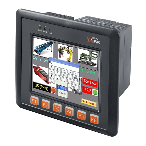
ICP DAS CO., LTD. would like to congratulate you own your purchase of our
ISaGRAF PACs - VP-2117. The ease to integration of the controller system and
the power of the IEC 61131-3 ISaGRAF software program combine to make a
powerful, yet inexpensive industrial process control system.
ISaGRAF PAC Series of ICP DAS includes :
PAC:
PAC-7186EG, PAC-7186PEG , I-7188EG, I-7188XG,
iPAC:
iP-8447, iP-8847, I-8437-80, I-8837-80, I-8417, I-8817,
WinPAC: WP-8147, WP-8447, WP-8847 (WinCon: W-8347, W-8747)
ViewPAC: VP-2117, VP-2xW7
Legal Liability
ICP DAS CO., LTD. assumes no liability for any and all damages that may be
incurred by the user as a consequence of this product. ICP DAS CO., LTD.
reserves the right to change this manual at any time without notice.
ICP DAS CO., LTD. constantly strives to provide our customers with the most
reliable and accurate information possible regarding our products. However, ICP
DAS CO., LTD. assumes no responsibility for its use, or for any infringements of
patents or other rights of third parties resulting from its use.
Trademark & Copyright Notice
The names of products are used for identification purposes only, and are the
registered trademarks of their respective owners or companies.
Technical Service
Please contact local agent or email problem-report to
New information can be found at www.icpdas.com.
www.icpdas.com FAQ Software ISaGRAF
Please visit
Asked Questions.
Written by Chun Tsai, Spike Huang ; Edited by Janice Hong.
Copyright © 2010 by ICP DAS CO., LTD. All Rights Reserved.
+7(495)109-02-08 sales@bbrc.ru www.bbrc.ru
Getting Started: VP-2117
VP-2117 Getting Started, Apr. 2010, V1.0
service@icpdas.com
for Frequently
.
1
Advertisement
Table of Contents

Related Manuals for ICP DAS USA VP-2117


Summary of Contents for ICP DAS USA VP-2117
- Page 1 ICP DAS CO., LTD. would like to congratulate you own your purchase of our ISaGRAF PACs - VP-2117. The ease to integration of the controller system and the power of the IEC 61131-3 ISaGRAF software program combine to make a powerful, yet inexpensive industrial process control system.
-
Page 2: Table Of Contents
Setup COM Port‟s Baud rate & Non- Modbus Slave Port from PAC ....3-4 Deleting an ISaGRAF Project from the Controller ..........3-6 Connecting PC to the VP-2117 Ethernet Port ............. 3-7 Modbus Slave Connection to the VP-2117 ............3-9 Setting VP-2117‟s IP &... - Page 3 Using N-Port COM .................... 3-22 3.18 Pin Assignment of Communication Ports ............3-23 3.19 Dimension ......................3-24 Show String on the VP-2117’s LCD .............. 4-1 Chapter 4 Writing a Simple ISaGRAF Program ..............4-1 4.1.1 Open ISaGRAF-Project Management ............4-2 Creating An ISaGRAF User‟s Group ............
-
Page 4: Reference Guide
Power Supply : DP-665/660, KA-52F http://www.icpdas.com > Products > Accessories > Power_Supply High profile I-8K/87K Series I/O Modules http://www.icpdas.com/products/PAC/i-8000/io_support_list.htm FAQ: FAQ Software ISaGRAF for Frequently Please visit www.icpdas.com Asked Question, or visit http://www.icpdas.com/faq/isagraf.htm VP-2117 Getting Started, Apr. 2010, V1.0... -
Page 5: Performance Comparison Table Of Isagraf Pacs
+7(495)109-02-08 sales@bbrc.ru www.bbrc.ru Performance Comparison Table of ISaGRAF PACs Please click on the link ISaGRAF Comparison Table or follow the below steps: 1. www.icpdas.com 2. Click here to go to the ISaGRAF page 3. Comparison Table VP-2117 Getting Started, Apr. 2010, V1.0... -
Page 6: Specifications: Vp-2117
0 ~ 2. RS-232: TxD, RxD, GND, Speed: 115200 bps max. Program COM1 downloads port. RS-485: D+, D- ; Speed: 115200 bps max. COM2 2500 V isolated. RS-232/RS-485, COM3 RS-232:TxD,RxD,GND,CTS,RTS ; RS-485:DATA+,DATA-, VP-2117 Getting Started, Apr. 2010, V1.0... - Page 7 Address Bus Range 2 K for each slot MMI (Man Machine Interface) LCD Type and Size STN, 128x64 Dot Matrix LCD English + Simplified Chinese (VP-2117) or Text Font English + Traditional Chinese (VP-2117-TC) Display Mode Text + Graphics...
- Page 8 I-7530 (RS-232 to CAN CAN/CANopen converter) to support CAN/CANopen devices and sensors. One VP-2117 supports max. 3 RS-232 Ports to connect max. 3 I-7530. Please refer to www.icpdas.com > FAQ > Software > ISaGRAF Ver.3 (English) >...
-
Page 9: Chapter 1 Typical Application
Software Protection (PWR, RUN, LAN1, L1, L2, L3; IP65 Compliant Front Panel L1 ~ L3 for User Programmable) Note: VP-2117 only support I-8K, I-87K High Profile I/O modules plugged on slot 0 ~ 2. VP-2117 Getting Started, Apr. 2010, V1.0... -
Page 10: Multi-Hmi & Local/Remote I/O
Users can choose RS-485 Remote I/O modules (I/7000, M-7000) or expansion units (RU-87Pn, I-87Kn) plugged with I-87K high profile I/O modules. With Modbus TCP/IP protocol, up to 6 PCs can link to one VP-2117. Redundant Bus7000 VP-2117 Getting Started, Apr. 2010, V1.0... -
Page 11: Data Exchange Through Ethernet & Rs-485
ГК Атлант Инжиниринг – официальный представитель в РФ и СНГ +7(495)109-02-08 sales@bbrc.ru www.bbrc.ru Data Exchange through Ethernet & RS-485 VP-2117 can support Ebus (Ethernet) and Fbus (RS-485) ctive Control Data and I/O Acquisition Data Reporting System For more information, please refer to www.icpdas.com >... -
Page 12: Constructions Monitoring Application (Vw Sensor)
> FAQ > Software > ISaGRAF Ver.3 (English) > FAQ-091 Modbus Converter of I-7000 & I-87K I/O VP-2117 can be a Modbus RTU serial & TCP/IP converter of I-7000 & I-87K Remote I/O modules. VP-2117 Getting Started, Apr. 2010, V1.0... -
Page 13: Motion Control
Z-index (FAQ-100) ; I-8090W: 3-axis SMS: Short Message Service VP-2117 can integrate with a GSM Modem to SMS: Short Message Service. This allows user to request information or perform control tasks for the ISaGRAF PAC via his personal cellular phone. In addition, the PAC can also send information and alarms to user's cellular phone. -
Page 14: Modbus Master
COM5 in multi serial port board) can support Modbus RTU Master or ASCII Master Protocol to connect to other Modbus Slave devices. NOTE: When the I-8112iW/8114W/8114iW/8142iW/8144iW expansion board plugged, COM5 ~ COM16 will be added. http://www.icpdas.com/products/PAC/i-8000/8000_IO_modules.htm VP-2117 Getting Started, Apr. 2010, V1.0... -
Page 15: Send Email With One Attached File
> FAQ > Software > ISaGRAF Ver.3 (English) > FAQ-067 1.12 Integrate with CAN/CANopen Devices and Sensors For more information, please refer to www.icpdas.com > FAQ > Software > ISaGRAF Ver.3 (English) > FAQ-086 VP-2117 Getting Started, Apr. 2010, V1.0... -
Page 16: Fast Frnet Remote I/O
ГК Атлант Инжиниринг – официальный представитель в РФ и СНГ +7(495)109-02-08 sales@bbrc.ru www.bbrc.ru 1.13 Fast FRnet Remote I/O For more information, please refer to www.icpdas.com > FAQ > Software > ISaGRAF Ver.3 (English) > FAQ-082 VP-2117 Getting Started, Apr. 2010, V1.0... -
Page 17: Zigbee Wireless Solution
Remote I/O control and data acquisition. For more information, please refer to www.icpdas.com > FAQ > Software > ISaGRAF Ver.3 (English) > FAQ-110 VP-2117 Getting Started, Apr. 2010, V1.0... - Page 18 ГК Атлант Инжиниринг – официальный представитель в РФ и СНГ +7(495)109-02-08 sales@bbrc.ru www.bbrc.ru...
-
Page 19: Chapter 2 Installing Software
3.5x ISaGRAF-256-E or ISaGRAF-256-C or ISaGRAF-32-E or ISaGRAF-32-C) to install on his PC to edit, download, monitor & debug the controller system. Item (B) is free and it is burned inside the CD-ROM which is delivered with the VP-2117. Operating system Requirements:... -
Page 20: The Hardware Protection Device (Dongle & Usb Key-Pro)
\Sentinel\SSD5411-32bit.exe in the ISaGRAF 3.55 CD-ROM (or later version) after you have installed the ISaGRAF. Then please reset your PC. 2. To run ISaGRAF Ver. 3.5x, please always plug the USB protection-key in the PC‟s USB port. VP-2117 Getting Started, Apr. 2010, V1.0... -
Page 21: Important Notice For Window 2000 Users
Anywhere within the [WS001] header portion of the isa.ini initialization file, add the entry shown below within the [WS001] header: [WS001] NT=1 Isa=C: \ISAWIN IsaExe=C: \ISAWIN\EXE Group=Samples IsaApl=c: \isawin\smp IsaTmp=C: \ISAWIN\TMP VP-2117 Getting Started, Apr. 2010, V1.0... -
Page 22: Step 2 - Installing The Icp Das Utilities For Isagraf
Ch 2.1 Step 1 before continuing. There is a CD-ROM supplied with each of the VP-2117 PACs with the ICP DAS Utilities for ISaGRAF . Please insert the CD-ROM into your CD-ROM drive. Then run CD-ROM: \napdos\isagraf\setup.exe. Follow the steps to install it. -
Page 23: Chapter 3 Hardware System & Setting
: Cancel First, power off the VP-2117 PAC, then press and hold on the F1 and F6 button and then power it up. In the setup mode, you will see ,: Change the Selection and Enter Key is OK . -
Page 24: Connecting Pc To The Vp-2117"S Com1
When you receive your VP-2117 PAC, there is one RS-232 communication cable (CA-0915) provided with the system. The cable is used to connect your PC to the VP-2117 or to an I-7520R (RS-232/485 converter) that can be purchased from ICP DAS. -
Page 25: Connecting Pc To Vp-2117"S Com2
Connecting PC to Several VP-2117’s COM2 An additional feature of using the COM2 Port of the VP-2117 is that you can configure an RS-485 network from one PC to link to numerous VP-2117 PACs. The PC can download ISaGRAF applications to each PAC on the RS-485 network. The maximum number of PACs that can be networked via the RS-485 network is 255 (Not recommended to use so many). -
Page 26: Setup Com Port"S Baud Rate & Non- Modbus Slave Port From Pac
Setup COM1/COM2/COM3’s baud rate & Non-Modbus Slave Port : First, power off the VP-2117 PAC, then press and hold on the F1 and F6 button, and then power it up. In the setup mode, you will see ,: Change the Selection and Enter Key is OK . - Page 27 The ISaGRAF workbench‟s default setting for PC‟s COM1 ~ 9 is 19200, 8, N, 1. If you have changed the VP-2117 COM1/2/3‟s baud rate to other value. You should change your ISaGRAF Workbench‟s COMM. to the same setting before they can link to each other.
-
Page 28: Deleting An Isagraf Project From The Controller
: Cancel First, power off the VP-2117 PAC, then press and hold on the F1 and F6 button and then power it up. In the setup mode, you will see ,: Change the Selection and Enter Key is OK . -
Page 29: Connecting Pc To The Vp-2117 Ethernet Port
On your PC: Please open an ISaGRAF project and select the program you want to download to the VP-2117 controller, and then press the Link Setup button on the project screen as shown below. A PC-PLC Link Parameters dialog box will appear as shown below. From here, please enter the NET-ID and select the Ethernet communication options then click on the Setup button. - Page 30 +7(495)109-02-08 sales@bbrc.ru www.bbrc.ru When you enter the appropriate information and press the OK button, you have completed the configuration and can communicate with the VP-2117 PAC via Ethernet successfully. Please click on Debug to connect the controller. As follows diagram, the program is running now. (if you receive a No application running means that your PAC does not download any program, please refer to Section 2.5.1...
-
Page 31: Modbus Slave Connection To The Vp-2117
The Modbus TCP/IP protocol‟s Ethernet Port No. is fixed as 502. Up to 6 PCs can link to one VP-2117 throughout Ethernet Port. Another PC or HMI can link to COM1: RS-232 Port or one of COM2: RS-485, COM3: RS-232/485 (Modbus RTU Slave protocol) of the PAC. -
Page 32: Setting Vp-2117"S Ip & Mask & Gateway
2. Run \vp2k\7188xw.exe in your hard drive. A 7188xw screen will appear. 3. Link from COM1 or COM2 of PC to COM1 of the VP-2117 PAC by a RS-232 cable (CA-0915). If you use other COM Port (ex.COM5), please refer to ch3.10... - Page 33 12. On PC, you can press Start > Run… > Input cmd to open the Command Prompt window, and then Input ping … (IP) to confirm the connection between PC and PAC is well. 3-11 VP-2117 Getting Started, Apr. 2010, V1.0...
-
Page 34: Update Vp-2117"S Hardware Driver
(CA-0915). If you use other COM Port (ex.COM5), please modify the first line of 7188xw.ini . 5. Power off the VP-2117, change the DIP switch on the left side of control panel to Init , and then power it up. - Page 35 4. Press ALT+X to quit 7188xw to avoid COM1/COM2 of the PC always been occupied. 5. Please change the DIP switch on the left side of control panel to Run , then reboot the VP-2117 PAC. 3-13 VP-2117 Getting Started, Apr. 2010, V1.0...
-
Page 36: Backup & Restore An Isagraf Project
Archive window, then click on the Restore button. The ISaGRAF project will now be restored to the sub-directory you designated. You can now open, edit and download the restored ISaGRAF project file. 3-14 VP-2117 Getting Started, Apr. 2010, V1.0... -
Page 37: The Connection Mode Of Fbus
For detailed ISaGRAF User‟s Manual. The Fbus is listed in Chapter 7. 3.13 Setting I-7000 and I-87K Remote I/O by DCON Utility VP-2117 PAC system can link up to 64 pcs ICP DAS's Remote I/O modules - I-7000 and I-87K series Remote I/O modules. - Page 38 I-87K4/5/8 /9. For example, switch Dip-1 to ON and restart I-87Kn, the Slot1 will setup to initial. When use I-87K5/9 you must start from the second slot (slot1), CAN NOT use the first slot (slot0). 3-16 VP-2117 Getting Started, Apr. 2010, V1.0...
- Page 39 Step 4: Click Searched module ID and give the new configuration Click when it is searched and double click module number to enter the setup screen. As screen below, you can setup the Address, Baud rate, Checksum, and then click Setting to save. 3-17 VP-2117 Getting Started, Apr. 2010, V1.0...
- Page 40 ON (Ex. I-87Kn), and then click Setting button again. In this screen, you have completed the settings, please disconnect the INIT and reboot the power. Finally, you can search the module again and check the settings. 3-18 VP-2117 Getting Started, Apr. 2010, V1.0...
-
Page 41: Linking I-7000 And I-87K Modules For Remote I/O
DATA+ signal, and the DATA- to the DATA- signal. As below diagram: You can link up to 64 I-7000 or I-87K series remote modules to one VP-2117 PAC. You must remember to set each I-7000 and I-87K remote module must have a unique address, and be set to the same baud rate as the VP-2117 PAC. -
Page 42: Creating A Modbus Link With The Pac
Each device on the link must have a unique NET ID (1 ~ 255) address, and communicate at same baud rate settings. If COM1 : RS-232 is used, you can only link one VP-2117 to ONE other Modbus device. To use the COM1 as Modbus Master Port, please disable the default Modbus RTU Slave setting in it. -
Page 43: Linking To An Mmi Interface Device
If you are using any of the Touch series of MMI devices (Ex: Touch506L/506S/ 510T…etc.) to connect to a PAC, you can only interface the devices to the COM1 Port on the VP-2117 PAC. Touch LCD Monitor: http://www.icpdas.com/products/HMI/touch_lcd/touch_list.htm 3-21 VP-2117 Getting Started, Apr. 2010, V1.0... -
Page 44: Using N-Port Com
+7(495)109-02-08 sales@bbrc.ru www.bbrc.ru 3.17 Using N-Port COM There are some N-Port COM boards that can be used to extend communication ability of the VP-2117 PAC. The model No. available is as below. 1:RS-232 4:RS-485 I-8112iW: 2-ch Isolated RS-232 Expansion Module... -
Page 45: Pin Assignment Of Communication Ports
ГК Атлант Инжиниринг – официальный представитель в РФ и СНГ +7(495)109-02-08 sales@bbrc.ru www.bbrc.ru 3.18 Pin Assignment of Communication Ports 3-23 VP-2117 Getting Started, Apr. 2010, V1.0... -
Page 46: Dimension
ГК Атлант Инжиниринг – официальный представитель в РФ и СНГ +7(495)109-02-08 sales@bbrc.ru www.bbrc.ru 3.19 Dimension Unit: mm 3-24 VP-2117 Getting Started, Apr. 2010, V1.0... -
Page 47: Chapter 4 Show String On The Vp-2117'S Lcd
We are going to use ISaGRAF Workbench to write a simple ISaGRAF example program, then download it to the VP-2117 controller to make it work. If you haven‟t installed SaGRAF & ICP DAS Utilities for ISaGRAF , please go back to read chapter This example contains one LD program. -
Page 48: Open Isagraf-Project Management
After click OK, the group name will show here. 4.1.3 Creating a New ISaGRAF Project To start a new ISaGRAF project, click on the Create New Project tool button and then enter the name (ex. example1) for the new project. VP-2117 Getting Started, Apr. 2010, V1.0... -
Page 49: Declaring The Isagraf Project Variables
Double click on the new project name (ex. example1) to open the project. Double click on the name of the new project to open it. Declaring the ISaGRAF Project Variables 4.1.4 Before you can start creating an ISaGRAF program, you must first declare the related variables. VP-2117 Getting Started, Apr. 2010, V1.0... - Page 50 You MUST make sure that the variable you have declared has the desired attribute assigned. If you want to change the attribute, just double click on the variable name and you can reassign it. VP-2117 Getting Started, Apr. 2010, V1.0...
- Page 51 4. Press the Store button to save it. The variable has now been declared. Please follow the above steps to declare the other variable – LCD_Q in this example. Refer to Global integers/reals window as below. VP-2117 Getting Started, Apr. 2010, V1.0...
- Page 52 2. Select the Internal as the variable attribute in Attributes items. 3. Enter the initial value as T#1s in Initial Value entry box. 4. Press the Store button to save it, the variable has now been declared. Refer to Global timers window as below. VP-2117 Getting Started, Apr. 2010, V1.0...
- Page 53 1. Enter the variable name (ex. STR_ ) in Name entry box. 2. Select the Internal as the variable attribute in Attributes items. 3. Enter the string as ICPDAS VP-2117 in Init. entry box. 4. Press the Store button to save it, the variable has now been declared.
-
Page 54: Create The Ld - Ld1 Program
4. Select Begin: Main Program in Style drop-down menu. You also can write notes in Comment entry box if necessary. Now you have one program inside this project. Please double click on the LD1 to get into it. VP-2117 Getting Started, Apr. 2010, V1.0... -
Page 55: Edit The Ld1 Program
We are going to write the first line of the LD1 program. Move the cursor to the contact and then click on tool button - F7 (Block on the right) to insert a Block to the right of contact . VP-2117 Getting Started, Apr. 2010, V1.0... - Page 56 As below figure, double-click the left side of X_ and Y_ parameters to open Select variable window. The X_ and Y_ indicates the location of String in LCD. X_ means the location of column (range:0 ~15), Y_ means the location of row VP-2117 Getting Started, Apr. 2010, V1.0 4-10...
- Page 57 Double-click the STR_ to assign it. As below figure, double-click the left side of LEN_ to open the Select variable window. LEN_ indicates the length of String (range: 1 ~ 64) and it must be constant pattern. VP-2117 Getting Started, Apr. 2010, V1.0 4-11...
- Page 58 Mode 1: Display the string, Mode 2: Highlight the string, Mode 3: Blinking the string. When you select the “Integer/Real”, you can see the name of string variable. Double-click the “Mode” to assign it. VP-2117 Getting Started, Apr. 2010, V1.0 4-12...
- Page 59 Double-click the LCD_Q to assign it. As below figure, the LD program has been completed. Click on tool button - Save to save the program and click X to exit. VP-2117 Getting Started, Apr. 2010, V1.0 4-13...
-
Page 60: Connecting The I/O
Click on lcd_bri and double-click on lcd_bright to setup the default brightness value (range: 0 ~ 10). Set to 0: backlight off ; Set to 10: Maximum brightness. After configuration, please click OK to confirm and then click Save to save it. VP-2117 Getting Started, Apr. 2010, V1.0 4-14... -
Page 61: Compiling & Simulating The Example Project
First, click on the menu bar Make > Compiler options as shown below. The Compiler Options window will now appear. Make sure to select the options as shown below then press the OK button to complete the compiler option selections. VP-2117 Getting Started, Apr. 2010, V1.0 4-15... - Page 62 Time to Simulate the Project! If the compilation is Ok, you may simulate the project on the PC to see how the program works without the controller. To do that, click on the Simulate tool button. VP-2117 Getting Started, Apr. 2010, V1.0 4-16...
- Page 63 Running the Simulation Program You can click on the variable name to change its value and status. In this example, ''LCD_STR'' is to show the string on the VP-2117's LCD, so the return value (LCQ_Q) in the simulation process is 0.
-
Page 64: Download & Debug The Example Project
ГК Атлант Инжиниринг – официальный представитель в РФ и СНГ +7(495)109-02-08 sales@bbrc.ru www.bbrc.ru Download & Debug the Example Project We have two ways to download the project to the VP-2117. One is using one is using RS-232 cable, the other one is using Ethernet cable (Refer to Section 3.7). - Page 65 If the development PC and the VP-2117 controller system are communicating properly with each other, the following window displayed below will appear. If there is a previous program running in the VP-2117 PAC , the project name and the word "active" will show on the screen).
- Page 66 As below, click on the I/O Connections icon in the ISaGRAF - Debug programs window to open the I/O Connections screen. In the lcd_init I/O board, you may change the lcd_bri status (0 - 10) to control the LCD backlight brightness. VP-2117 Getting Started, Apr. 2010, V1.0 4-20...
- Page 67 You may also click on Dictionary to see the real time variable state. Another VERY helpful window you can open is the Quick LD Program window. From this window you can observe the LD program being executed in real time. VP-2117 Getting Started, Apr. 2010, V1.0 4-21...
- Page 68 ГК Атлант Инжиниринг – официальный представитель в РФ и СНГ +7(495)109-02-08 sales@bbrc.ru www.bbrc.ru...
-
Page 69: Appendix
Appendix A. ISaGRAF User Manual & Demo Program & FAQ The related ISaGRAF manuals and demo programs are all in your VP-2117 CD. You can also follow the steps below to view the latest information and FAQ in ISaGRAF website. -
Page 70: Using Modbus Tcp/Ip Protocol To Control Isagraf Controllers With Vb
> FAQ > Software > ISaGRAF Ver.3 (English) 2. VB 6.0 Demo program using Modbus TCP/IP protocol to control ISaGRAF controllers. Please refer to below website: www.icpdas.com > FAQ > Software > ISaGRAF Ver.3 (English) VP-2117 Getting Started, Apr. 2010, V1.0... -
Page 71: How To Detect The Status Of Hot Swap For I-87K
+7(495)109-02-08 sales@bbrc.ru www.bbrc.ru B. How to Detect the Status of Hot Swap for I-87K By using I-87K (High Profiles) modules, VP-2117 can support Hot Swap function. This feature allows users to plug or unplug modules without shutting down the power. And you could check current I/O status by ISaGRAF Workbench. First click the I/O connection icon to bring up the window;... -
Page 72: How To Detect The Status Of Dual Battery
There are two ways to retrieve Dual battery power status on VP-2117: A. Check the current power status when the system boots up ... -
Page 73: 10-Ch Thermocouple Input Module
4. Up to 240 V over voltage protection is provided. 5. It features per-channel open wire detection for thermocouple and 4 to 20mA inputs For more details, please visit the web site listed below: http://www.icpdas.com/products/Remote_IO/i-7000/i-7018z.htm I-7018Z: http://www.icpdas.com/products/Remote_IO/i-87k/i-87018z.htm I-87018Z: VP-2117 Getting Started, Apr. 2010, V1.0... -
Page 74: Ru-87P1/2/4/8
I-87K I/O Slots 87Pn power CPU power System ready Auto Configuration Enable/Disable Address Rotary Switch Slot 0 Slot 1 Slot 2 Slot 3 Configuring Dip Switch Power connector Slots LED indicators Fig. 1 RU-87P4 VP-2117 Getting Started, Apr. 2010, V1.0... - Page 75 DCON Utility: for configuration OPC Servers EZ Data Logger Support Variant Software Develop Toolkits Free DLL, ActiveX, Labview driver, Indusoft driver, DasyLab driver, Linux driver ISaGRAF PACs can connect to the RU-87Pn directly VP-2117 Getting Started, Apr. 2010, V1.0...
Need help?
Do you have a question about the VP-2117 and is the answer not in the manual?
Questions and answers