
Related Manuals for ICP DAS USA PET-7060


Summary of Contents for ICP DAS USA PET-7060
- Page 1 PET-7000 series Power over Ethernet Remote I/O Module User Manual (For Digital I/O Modules)
- Page 2 Warranty All products manufactured by ICP DAS are under warranty regarding defective materials for a period of one year, starting from the date of delivery to the original purchaser. Warning ICP DAS assumes no liability for damages resulting from the use of this product.
- Page 3 Original Issue 1.00 May 2009 PET-7000 Support List This manual is for the following modules: Module Description 6-channel Power Relay DO and 6-channel Isolated DI Module PET-7060 8-channel Power Relay DO Module PET-7067 PET-7000 DIO User Manual, May 2009, V1.00, EMH-013-10----------3...
-
Page 4: Table Of Contents
Table of Contents INTRODUCTION..............................7 1.1................................. 8 EATURES 1.2.............................. 11 PECIFICATIONS 1.3............................12 ODULE ELECTION 1.4. PET-7000 ..........................18 IEW OF THE 1.5. PET-7000 ..........................22 INSTALLATION 1.5.1. Mounting the PET-7000..........................22 1.5.2. Connecting the Hardware......................... 26 1.5.3. - Page 5 I/O PAIR CONNECTION............................ 81 SOFTWARE DEVELOPMENT APPLICATION ..................... 82 6.1....................82 OCATION OF DOCUMENTS AND SOFTWARE 6.2. VIEW..............................84 OPC SERVER ............................... 85 7.1..............................85 NTRODUCTION 7.2....................... 86 ROCEDURE FOR USING THE SERVER 7.3. OPC S MODBUS ..................
- Page 6 TABLES Table 1-1 ET-7000 classification ..................12 Table 1-2 LED Indicators ....................19 Table 1-3 J2 Connector ....................19 Table 1-4 RJ-45 Wiring Standards................28 Table 3-1 TCP/IP network settings ................42 Table 3-2 Basic Settings....................48 Table 3-3 Load All Setup Default Table ..............49 Table 3-4 Input or Holding Data Types ...............60 Table 3-5 Main Web HMI Page - Table1 ..............62...
-
Page 7: Introduction
Chapter 1 Introduction 1. Introduction The PET-7000 features “PoE” technology, not only data but power is carried through an Ethernet cable. This feature makes installation of the PET-7000 a piece of cake. Imagine that no more unnecessary wires, only an Ethernet cable takes care of everything in the field. -
Page 8: Features
Chapter 1 Introduction 1.1. Features Built-in web server Each PET-7000 module has a built-in web server that allows the user to easily configure, monitor and control the module from a remote location with a regular web browser. Web HMI The Web HMI function allows the user to create dynamic and attractive web pages to monitor and control the I/O points. - Page 9 Chapter 1 Introduction I/O Pair Connection This function is used to create a DI to DO pair through the Ethernet. Once the configuration is complete, the PET-7000 module can poll the status of remote DI status with the Modbus/TCP protocol and continuously write to the paired local DO channels in the background.
- Page 10 Chapter 1 Introduction All-in-one module The various I/O components are mixed with multiple channels in a single module, which provides the most cost effective I/O usage and enhances performance of the I/O operations. 2-way isolated noise/surge protection To protect the hardware from damage caused by noise and surge, the PET-7000 module is designed with isolation circuits for Ethernet, and I/O.
-
Page 11: Specifications
Chapter 1 Introduction 1.2. Specifications System CPU: 80186-80 or compatible EEPROM: 16 KB SRAM: 512 KB FLASH ROM: 512 KB Communication Ethernet Port: (10/100MBaseT, RJ-45 Port) Built-in WatchDog Timer (0.8 seconds) LED indicators PoE On L1: Run L2: Ethernet (Link/Active) L3: 10/100M Isolation I/O Isolation:... -
Page 12: Module Selection
Chapter 1 Introduction 1.3. Module Selection PET-7000 classification PET-7XYZ ET: Ethernet communication interface X: Number of the variance Y: Function code Z: Extension function code Table 1-1 PET-7000 classification 1. AI module 3. RTD 4. Transmitter 5. Thermistor 6. Strain Gauge 7. - Page 13 Chapter 1 Introduction Released Module Type Module Description 6-channel Power Relay Output PET-7060 6-channel Isolation DI Module Power Relay Output 8-Channel Power Relay Output Module PET-7067 PET-7000 DIO User Manual, May 2009, V1.00, EMH-013-10----------13...
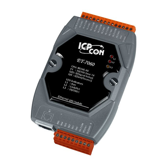
- Page 14 Chapter 1 Introduction PET-7060 Layout and Pin Assignments PET-7000 DIO User Manual, May 2009, V1.00, EMH-013-10----------14...
- Page 15 Chapter 1 Introduction PET-7060 I/O Specifications: Digital Output Channels Output Type Power Relay, Form A (SPST N.O.) Operating Voltage Range 250 VAC /30 VDC Max. Load Current 5.0 A/channel at 25 °C Operating Time 6 ms Release Time 3 ms VDE 5 A 250 VAC 30,000 ops (10 ops/minute) at 75°C...
- Page 16 Chapter 1 Introduction PET-7067 Layout and Pin Assignments PET-7000 DIO User Manual, May 2009, V1.00, EMH-013-10----------16...
- Page 17 Chapter 1 Introduction PET-7067 I/O Specifications: Digital Output Channels Output Type Power Relay, Form A (SPST N.O.) Operating Voltage Range 250 VAC / 30 VDC Max. Load Current 5.0 A/channel at 25 °C Operating Time 6 ms Release Time 3 ms VDE 5A 250 VAC 30,000 ops (10 ops/minute) at 75 °C 5A 30 VDC 70,000 ops (10 ops/minute) at 75 °C Electrical Life ( Resistive load )
-
Page 18: View Of The Pet-7000
Chapter 1 Introduction 1.4. View of the PET-7000 Front Panel Description J1 Connector Indicators J2 Connector PET-7000 DIO User Manual, May 2009, V1.00, EMH-013-10----------18... -
Page 19: Table 1-2 Led Indicators
Chapter 1 Introduction Table 1-2 LED Indicators Name LED Action Function Flashing Firmware is running Ethernet link detected LINK/ACT No Ethernet link detected Flashing Green Ethernet packet received 10/100M Speed 10 Mbps Orange Speed 100 Mbps Note: If the Run LED does not display the information as above, the following steps should be taken: Power-off the module Check that the Init/Normal switch is in the Normal position. - Page 20 Chapter 1 Introduction Back Panel Description Init/Normal switch Init mode: MiniOS7 configuration mode Normal mode: Firmware running mode During the PET-7000 working time, the Switch is ALWAYS in the Normal position. Only when updating the PET-7000 firmware or OS, the switch can be moved from the Normal position to the Init position.
- Page 21 Chapter 1 Introduction Bottom Panel Description RJ45 Port Frame Ground Note: Appendix F describes how to connect the Frame Ground to the PET-7000 series PET-7000 DIO User Manual, May 2009, V1.00, EMH-013-10----------21...
-
Page 22: Pet-7000 Installation
Chapter 1 Introduction 1.5. PET-7000 installation 1.5.1. Mounting the PET-7000 DIN Rail Mounting There are three new DIN rail models available. Each is made of stainless steel, which is stronger than those made of aluminum. There is a screw at one end and a ring terminal is included so that it can be easily connected to the earth ground. - Page 23 Chapter 1 Introduction Part number Max number of modules Dimensions DRS-240 240 mm x 35 mm Part number Max number of modules Dimensions DRS-125 125 mm x 35 mm Note: The recommended wire to connect to the earth ground is 16 – 14 AWG wire. PET-7000 DIO User Manual, May 2009, V1.00, EMH-013-10----------23...
- Page 24 Chapter 1 Introduction Piggyback Mounting Wall Mounting PET-7000 DIO User Manual, May 2009, V1.00, EMH-013-10----------24...
- Page 25 Chapter 1 Introduction Snap the PET-7000 onto the DIN-rail (refer to the Snap On picture below) Snap the PET-7000 off from the DIN-rail (refer to the Snap Off picture below) PET-7000 DIO User Manual, May 2009, V1.00, EMH-013-10----------25...
-
Page 26: Connecting The Hardware
Chapter 1 Introduction 1.5.2. Connecting the Hardware Step 1: Connect the Ethernet cable between the PET-7000 and the PoE switch. Pin31 Pin30 Step 2: Check that the “RUN” LED (L1) on the PET-7000 is periodically ON for 0.5 seconds and then OFF for 0.5 seconds. Notes: Pin 8 and Pin 9 on the J2 connector are designed as VS+ and GND for the auxiliary power input (+12 ~ +48 VDC) if the PoE switch is lacked or the total... -
Page 27: Ethernet Cable Wiring
Chapter 1 Introduction 1.5.3. Ethernet cable wiring Connecting the PET-7000 to Switch or Hub Connecting the PET-7000 to a Host PC As a result of the automatic MDI / MDI-X crossover for plug-and-play on the PET-7000 RJ45 port, there is no need to a crossover cable to connect the PET-7000 to the Host PC. The user just uses a general straight-through cable to make the connection. -
Page 28: Table 1-4 Rj-45 Wiring Standards
Chapter 1 Introduction RJ-45 Cables Wiring Standard Pin-8 Pin-1 Table 1-4 RJ-45 Wiring Standards Pin Number Signal Function Transmit Data + Transmit Data - Receive Data + Not Used Not Used Receive Data - Not Used Not Used PET-7000 DIO User Manual, May 2009, V1.00, EMH-013-10----------28... -
Page 29: I/Owiring Connection
Chapter 1 Introduction 1.6. I/O wiring connection PET-7060 Note: Source type is provided with hardware PCB version 1.3 and later PET-7067 PET-7000 DIO User Manual, May 2009, V1.00, EMH-013-10----------29... -
Page 30: Software & Document Information
Chapter 1 Introduction 1.7. Software & Document information The location of all documents and software related to the PET-7000 module is shown in the following directory structure diagram. The relevant file can quickly be located by referring to the diagram. For details of the revision information, please refer to CD:\NAPDOS\PET7000\Firmware\Version_nnn_Eng.txt or Version_nnn_Chi.txt PET-7000 DIO User Manual, May 2009, V1.00, EMH-013-10----------30... -
Page 31: Update Information
Chapter 1 Introduction 1.8. Update Information Refer to http://www.icpdas.com/products/Remote_IO/et-7000/pet7k_manual_software.htm PET-7000 DIO User Manual, May 2009, V1.00, EMH-013-10----------31... -
Page 32: Configuring The Pet-7000
Chapter 2 Configuring the ET-7000 2. Configuring the PET-7000 The following settings need be set correct before the PET-7000 working. Network settings need meet the Network demand of Host PC; username and password settings are for the security issue. Network settings: Item Default IP Address... - Page 33 Chapter 2 Configuring the ET-7000 Step 3: Run MinioS7 utility as per the following diagram. Step 4: Select the Connection item of main menu, and then click the “Search” item. PET-7000 DIO User Manual, May 2009, V1.00, EMH-013-10----------33...
- Page 34 Chapter 2 Configuring the ET-7000 Step 5: The “MiniOS7 Scan” window appears, and starts to search the modules on this Ethernet network. Progress is running Step 6: When the search is finished, click the PET-7000 module which you want to configure and then click the “IP setting”...
- Page 35 Chapter 2 Configuring the ET-7000 Step 6: IP Setting window appears. Step 6.1: Check that valid IP, Mask, Gateway. Alias, DHCP values have been inserted into the “Recommend Settings” fields. Step 6.2: If these values are modified, click the “Set” button to set the new values. Step 7: When “Set”...
-
Page 36: Load Factory Default
Chapter 3 Web Configuration Page 2.2. Load Factory Default Refer to “Load All Setup Default” in Sec 3.2.2 Basic Setting for more details regarding loading the factory default using the Web configuration. PET-7000 DIO User Manual, May 2009, V1.00, EMH-013-10----------36... -
Page 37: Web Configuration Page
Chapter 3 Web Configuration Page 3. Web Configuration Page The PET-7000 series modules have a built-in Web configuration page with a friendly user interface; it is simple to configure the PET-7000 with using a regular web browser. The web configuration page is optimized for Microsoft Internet Explorer 6.0 and Mozilla Firefox, and the other browsers can work well, but the Web might appear differently. - Page 38 Chapter 3 Web Configuration Page After the user name and password are accepted, the PET-7000 home page will be displayed. Note: If either the user name or the password is incorrect or is left blank, the main home page and all other pages will not be accessible, so ensure that the input data is correct and rectify it if and as necessary.
- Page 39 Chapter 3 Web Configuration Page The brief description of the Web page configuration function is listed on six main functions of the tree structure. Overview: A brief introduction to the six functions Configuration: Network Settings, Serial Port, Basic and Module I/O Settings Authentication: Account Management and Accessible IP Settings...
-
Page 40: Overview
Chapter 3 Web Configuration Page 3.1. Overview The Welcome page for the PET-7000 contains information related to the currently accessed PET-7000 series module, as shown below: Model Name: PET-7000 series module name (The default is the PET-7000 series name. The maximum length is 8 characters) MAC address: The MAC address of the PET-7000 series module... - Page 41 Chapter 3 Web Configuration Page PET-7000 DIO User Manual, May 2009, V1.00, EMH-013-10----------41...
-
Page 42: Configuration
Chapter 3 Web Configuration Page 3.2. Configuration 3.2.1. Ethernet Settings The Ethernet settings page can be used to check and change the TCP/IP network settings of the PET-7000 module. Table 3-1 TCP/IP network settings Settings Description Range Factory default 4-byte IP address. Each PET-7000 X.X.X.1 module needs an IP address so that if 192.168.255.1... - Page 43 Chapter 3 Web Configuration Page DHCP Select this option If there is a DHCP server on the network, the IP address 0 (Disable) can be assigned automatically by the 0 (Disable) 1(Enable) server. Firmware Firmware Version and Date Varies depending Ver.
-
Page 44: Basic Settings
Chapter 3 Web Configuration Page 3.2.2. Basic Settings Module Name: The column shows the module name. The name can be modified by the user, and the maximum length of new name is 8 characters. Module Information: Indicates the alias name given to the module and can be modified by the user. The name can be a maximum of 16 characters, but cannot include single or double quotes (' or “... - Page 45 Chapter 3 Web Configuration Page After the new values are submitted and the PET-7000 is rebooted, the Module Name Module Information will be updated. You can refresh the web browser to verify the new values. Example: Click the Basic Setting in the Configuration section of the Main Menu tree. Enter a string into the Module Information text field, for example, Module1.
- Page 46 Chapter 3 Web Configuration Page Example: Click “Basic Settings” in the Configuration Section of the Main Menu tree. Enter a string in the Top page Information (First line) and Top page Information (second line) text fields, for example “ICPDAS” and “http://www.icpdas.com”. The font size and color can be modified by selecting an option from the color drop down box and entering a value in the font text field.
- Page 47 Chapter 3 Web Configuration Page Clicking the “More Information” in the Main Menu tree will automatically open the web page defined in the More Information URL. The default URL for “More information” is “http://www.icpdas.com/products/Remote_IO/ET- 7000/ET-7000_introduction.htm” Web Server TCP Port: The default well known port which is used in TCP to name the ends of logical connections for Web server of PET-7000 is 80.
-
Page 48: Table 3-2 Basic Settings
Chapter 3 Web Configuration Page It allows the user to change the port to other port. (0~65535) Table 3-2 Basic Settings Function Name Description Range Factory default Module Name The name of the PET- Maximum of 8 Depends on the 7000 series module characters type of the... -
Page 49: Table 3-3 Load All Setup Default Table
Chapter 3 Web Configuration Page Load All Setup Default Table 3-3 Load All Setup Default Table Function Name Details Factory default Configuration All of the Ethernet settings Refer to Table 3-1 All of the Module I/O settings Refer to Sec. 3.2.3 Authentication Account management The default account is... -
Page 50: Module I/O Settings
PET-7000 module. All settings can be divided into either common, DI, DO, AI and AO settings. Please refer to Appendix C for more details regarding PET-7000 Modbus register table. The illustration below shows the Modbus settings for the PET-7060 module PET-7000 DIO User Manual, May 2009, V1.00, EMH-013-10----------50... - Page 51 Chapter 3 Web Configuration Page PET-7000 DIO User Manual, May 2009, V1.00, EMH-013-10----------51...
- Page 52 Chapter 3 Web Configuration Page PET-7000 DIO User Manual, May 2009, V1.00, EMH-013-10----------52...
- Page 53 Chapter 3 Web Configuration Page Modbus Registers and Factory Defaults Common Functions Modbus Factory Points Description Range Address default 40257 Set host watch dog timer 5~65535 (Enable) 0 (Disable) (Second) (<5: Disable) DI Module Functions Modbus Points Factory Description Range Address (Max.) default...
-
Page 54: Authentication
Chapter 3 Web Configuration Page 3.3. Authentication 3.3.1. Account management Each PET-7000 series module provides access privilege for up to five user accounts including a default Admin account and four general user-defined accounts. Each of the user-defined accounts can be assigned either Admin or general user privilege. Assigning Admin privilege allows the account to read and write configuration settings but the general user account is restricted to read only access. -
Page 55: Ip Filter Settings
Chapter 3 Web Configuration Page 3.3.2. IP filter Settings Each PET-7000 series module contains an IP filter that can be used to control access to the module, thereby preventing unauthorized access from unknown IP addresses. The IP filter can be granted across a range of IPv4 addresses, such as from 10.0.8.1 to 10.0.9.22 or to a single IP address, with a maximum of ten permission rules. - Page 56 Chapter 3 Web Configuration Page There are three methods of restricting or granting access permissions. Allow one specific IP address only Enter the same IP address in both the “From IP address” and “TO IP address” text fields Allow Hosts within a specific IP address range Enter the first IP address in the From IP address text field, and enter the last IP address in the permitted range in the To IP address text field.
-
Page 57: Web Hmi
Chapter 3 Web Configuration Page 3.4. Web HMI 3.4.1. Web Editing The Web page configuration can be used to create a user-defined Web page. Click “Web Editing” in the “Web HMI” section of the Main menu tree and the window above will be displayed. - Page 58 Chapter 3 Web Configuration Page Page properties All properties can be configured on this page. The free space for picture Picture Preview File tree: The files exist on the ET-7000 module PET-7000 DIO User Manual, May 2009, V1.00, EMH-013-10----------58...
- Page 59 Chapter 3 Web Configuration Page A maximum of 10 items in each group can be configured. : The image file name selected by clicking the “Browse” button. The image file type can be either of .jpg, .gif or .bmp. The recommended resolution for the image to be displayed on the Editing Web page is 340 * 250 pixels.
-
Page 60: Table 3-4 Input Or Holding Data Types
Chapter 3 Web Configuration Page Editing the Group Register Modbus Register: The Modbus Register number for the PET-7000 module Alias: A string that describes the Modbus register. It can be a reference to a tag in the image of the Web editing page which is selected from the “Page properties” section. (If the tag of the Modbus register has defined on the image) Scaling: The Modbus register value will be divided by the scale value before being displayed on the web page, or multiplied before value is written to the PET-7000 module. - Page 61 Chapter 3 Web Configuration Page Unsigned 32 A 32-bit positive value. The Most significant word (register) is on the (swapped) high address. Signed 32 (Swapped) A 32-bit value with sign. The Most significant word (register) is on the high address. Float A 32-bit floating point.
-
Page 62: Web Hmi
The default start page is the Main Web HMI page shown as follow. The Main Web HMI page shows all the components of the PET-7000. For example, the Main Web HMI page for a PET-7060 module will display the 6 DO and 6 DI components. -
Page 63: Table 3-6 Main Web Hmi Page - Table 2
Chapter 3 Web Configuration Page Table 3-6 Main Web HMI Page - Table 2 Title Name Description Notes The Component type and address Register The Register address Action DO: ON (1), OFF (0) AO: A numeral of Integer or float Connection Status: The status indicates the connection status of the IO component on PET-7000 module defined on the cell of IO channel and Modbus register mapping table. - Page 64 Chapter 3 Web Configuration Page The color of the cells in the table shown on the Web page below have turned red, indicating that the connection to the module has failed. PET-7000 DIO User Manual, May 2009, V1.00, EMH-013-10----------64...
- Page 65 Chapter 3 Web Configuration Page Java Web page cannot be RUN If your Web browser isn’t JAVA enabled, a message notifying you that your Web browser can NOT run Java applets” message will be displayed on the Web HMI page. Depending on the type of Web browser, a dialog box will appear asking whether you wish to install Java or not.
- Page 66 Chapter 3 Web Configuration Page To test whether Java is installed or not, visit http://java.com/en/download/installed.jsp. Please refer to Appendix E for more details regarding JAVA installation. PET-7000 DIO User Manual, May 2009, V1.00, EMH-013-10----------66...
- Page 67 Chapter 3 Web Configuration Page An example of how to create a Web Editing Page Create a Web page to monitor the I/O of the conveyer system shown below. The I/O system contains 3 photo sensors that are used to detect the products, and 3 switches that are used to turn the conveyer motor on and off.
- Page 68 Chapter 3 Web Configuration Page Navigate to the required directory and select the appropriate image file. “conveyer.gif” is selected in this example. Highlight the file name and Click the “Open” button to make your selection. PET-7000 DIO User Manual, May 2009, V1.00, EMH-013-10----------68...
- Page 69 Chapter 3 Web Configuration Page Click “Upload” button to upload the selected file to the PET-7000 module. After the upload is completed, the “conveyer.gif” file should now be listed in the file tree and also in the image list box. 1.
- Page 70 Chapter 3 Web Configuration Page To add a register item, click the button in the first row of the “Group” table and the “Edit Group Register” window will be displayed. Add a new DI item using the Register Address 1, then select Discrete Input as the register type and enter “PHS1”...
- Page 71 Chapter 3 Web Configuration Page The new register item will now be displayed in the “Group” table. Add a DO register item by clicking on the Edit button on the second row of the “group” table then selecting the Register Address 1, select “Coil” as the Register type and enter the alias name “Motor 1”, as shown below..
- Page 72 Chapter 3 Web Configuration Page PET-7000 DIO User Manual, May 2009, V1.00, EMH-013-10----------72...
- Page 73 Chapter 3 Web Configuration Page An editing page named as “Conveyer” has added to the list box on the top left-hand side of the “Web Page Configuration” window. Select the “Conveyer” item and click button to browse to the “Conveyer” Web HMI page. PET-7000 DIO User Manual, May 2009, V1.00, EMH-013-10----------73...
- Page 74 Chapter 3 Web Configuration Page The “conveyer.gif” image file and all register items will be displayed on the “Conveyer” Web HMI page. Note: It is recommended that you check whether the browser is JAVA enabled before browsing the Web HMI. If Java is not installed, please refer to Appendix E for details of how to install JAVA.
-
Page 75: I/O Pair Connection
Chapter 3 Web Configuration Page 3.5. I/O Pair Connection The function makes a DI to DO pair through the Ethernet based on Modbus/TCP. Once the configuration is done, the PET-7000 can poll Remote DI status and then write to the paired local DO constantly in the background. - Page 76 Chapter 3 Web Configuration Page When the configuration is done, you can click “Pair” from “web page configuration” to open another page to view the pair connection again. PET-7000 DIO User Manual, May 2009, V1.00, EMH-013-10----------76...
-
Page 77: More Information
Chapter 3 Web Configuration Page 3.6. More Information The More Information menu item is a Web page URL, and can be used to provide a link to a web site containing additional information about the product maker, detailed specs etc. The Default More Information URL is: http://www.icpdas.com/products/Remote_IO/et- 7000/et-7000_introduction.htm Please refer to Sec. -
Page 78: How To Access The Pet-7000
Chapter 4 How to access ET-7000 4. How to access the PET-7000? The PET-7000 series is designed as remote I/O module that can be accessed via either an Ethernet or Serial interface. 4.1. Via an Ethernet Network Ethernet is an extremely popular networking format that already exists for most applications, either for use with local networks or for connecting to the Internet. -
Page 79: Using The Modbus Protocol
Chapter 4 How to access ET-7000 4.2. Using the Modbus protocol 4.2.1. Introduction MODBUS is a master-slave bus system in which only one device (the master) actively starts a transaction (query). The passive device (the slave) then sends a response. Most SCADA Supervisor Control And Data Acuisition and HMI software can easily integrate serial devices via the Modbus protocol, such as Citect, ICONICS, iFIX, InduSoft, Intouch, Entivity Studio, Entivity Live, Entivity VLC, Trace Mode, Wizcon, Wonderware, etc. -
Page 80: Function Codes Supported
Chapter 4 How to access ET-7000 4.2.2. Function Codes Supported Modbus function codes are different both the analog and digital types. Table 4-1 PET-7000 Modbus Function Code Modbus Command Protocol Description (Hex) Read multiple coils status for DO Read multiple input discrete for DI Read multiple registers for AO Read multiple input registers for AI Write single coil for DO... -
Page 81: I/O Pair Connection
Chapter 5 I/O Pair Connection 5. I/O Pair Connection The function is used to make a DI to DO pair through the Ethernet. The communication is based on Modbus/TCP. Once the configuration is done, the PET-7000 can poll remote DI status and then write to paired local DO constantly in the background. -
Page 82: Software Development Application
Chapter 6 Software Development Application 6. Software Development Application 6.1. Location of documents and software The following diagram illustrates the location of all documents and software related to Modbus applications for PET-7000 series modules. The relevant file can quickly be located by referring to the diagram. - Page 83 Chapter 6 Software Development Application There are a variety of applications that conform to the Modbus protocol, such as ActiveX, LabVIEW, InduSoft, OPC Server, etc. are available for use on the/a Host PC. These applications can be used to access the PET-7000 series module from the Host PC and contain a number of helpful free demo programs and documents, which can be found on the CD included in the shipping package, or can be downloaded from the ICP DAS web site or FTP site.
-
Page 84: Labview
Chapter 6 Software Development Application 6.2. LabVIEW LabVIEW is the best way to acquire, analyze, and present data. LabVIEW delivers a graphical development environment that can be used to quickly build data acquisition quickly, instrumentation and control systems, boosting productivity and saving development time. -
Page 85: Opc Server
Chapter 7 OPC Server 7. OPC Server 7.1. Introduction OPC (OLE for Process Control) is the first standard resulting from the collaboration of a number of leading worldwide automation suppliers working in cooperation with Microsoft. Originally based on Microsoft's OLE COM (Component Object Model) and DCOM (Distributed Component Object Model) technologies, the specification defines a standard set of objects, interfaces and methods for use in process control and manufacturing automation applications to facilitate interoperability. -
Page 86: Procedure For Using The Opc Server
Chapter 7 OPC Server 7.2. Procedure for using the OPC server Step 1: Read the following documents Readme.txt: contains the latest important information, including: • A list of files contained on the shipped CD Reversion.txt: contains the revision history information, including •... - Page 87 Chapter 7 OPC Server Step 4: New a Group and Tag PET-7000 DIO User Manual, May 2009, V1.00, EMH-013-10----------87...
- Page 88 Chapter 7 OPC Server Step 5: Load a finished OPC project file for ET-7060 PET-7000 DIO User Manual, May 2009, V1.00, EMH-013-10----------88...
- Page 89 Chapter 7 OPC Server Note: The OPC file for the ET-7060 is located at: CD:\NAPDOS\ET7000\Document\Application\NAPOPC\ET-7060 PET-7000 DIO User Manual, May 2009, V1.00, EMH-013-10----------89...
-
Page 90: Scada
Chapter 8 SCADA 8. SCADA SCADA stands for Supervisor Control And Data Acquisition. It is a production automation and control system based on PCs SCADA is wildly used in many fields e.g. power generation, water systems, the oil industry, chemistry, the automobile industry. Different fields require different functions, but they all have the common features: •... -
Page 91: Indusoft
Chapter 8 SCADA 8.1. InduSoft InduSoft Web Studio is a powerful, integrated collection of automation tools that includes all the building blocks needed to develop modern Human Machine Interfaces (HMI), Supervisory Control and Data Acquisition (SCADA) systems, and embedded instrumentation and control applications. InduSoft Web Studio’s application runs in native Windows NT, 2000, XP, CE and CE .NET environments and conforms to industry standards such as Microsoft .NET, OPC, DDE, ODBC, XML, and ActiveX. -
Page 92: Citect
Chapter 8 SCADA 8.2. Citect CitectSCADA is a fully integrated Human Machine Interface (HMI) / SCADA solution that enables users to increase return on assets by delivering a highly scalable, reliable control and monitoring system. Easy-to-use configuration tools and powerful features enable rapid development and deployment of solutions for any size application. -
Page 93: Ifix
Chapter 8 SCADA 8.3. iFix The document containing detailed instructions for linking to the PET-7000 module using the Modbus protocol is located on the shipped CD: \NAPDOS\ET7000\Document\Application\iFix ftp://ftp.icpdas.com/pub/cd/6000cd/napdos/et7000/document/application/ifix/ PET-7000 DIO User Manual, May 2009, V1.00, EMH-013-10----------93... -
Page 94: Troubleshooting And Technical Support
Chapter 9 Troubleshooting and Technical Support 9. Troubleshooting and Technical Support This chapter discusses methods of quickly diagnosing and fixing problems or errors without having to contact ICP DAS. When troubleshooting the following problems, please make sure that the module is switched on, and confirm that the physical connections are correct (power cable, network cable and serial cable) Note that some unexplained errors might be caused by duplicate IP addresses on the... - Page 95 Chapter 9 Troubleshooting and Technical Support The Web Configuration Enable the Web function has been disabled. Configuration function using (Shown on the Basic either the SMMI or the Settings page) console. The Web server TCP port Change the TCP port to 80 has been changed from port or reconnect the ET-7000 using the specific TCP port.
-
Page 96: Appendix A: Dimensions
Appendix A: Dimensions Appendix A: Dimensions PET-7000 DIO User Manual, May 2009, V1.00, EMH-013-10----------96... - Page 97 Appendix A: Dimensions Wall Mount Bracket 6 8 . 0 0 5 . 5 0 3 . 9 0 . 9 1 5 . 2 5 1 . 7 2 7 . 8 5 PET-7000 DIO User Manual, May 2009, V1.00, EMH-013-10----------97...
-
Page 98: Appendix B: Minios7 Utility
Appendix B: MiniOS7 utility Appendix B: MiniOS7 utility On occasions, ICP DAS will offer an update to the PET-7000 firmware or MiniOS7. The MiniOS7 utility is used to easily update your software to the latest version. The MiniOS7 Utility is used for both essential configuration and for downloading programs into the PET- 7000 controller embedded in the ICPDAS MiniOS7 environment. - Page 99 Appendix B: MiniOS7 utility Installation procedure Step 1: Locate and run MiniOS7 utility.exe from the CD: \NAPDOS\ET7000\Tools\Tools for MiniOS7\MiniOS7_utility directory. Step 2: After completing the installation, a new “ICPDAS” folder will be added to the “programs” section of the start menu. The MiniOS7_utility files can be accessed by clicking on this folder and then the 'MiniOS7 utility' folder.
- Page 100 Appendix B: MiniOS7 utility Step 3: After a connection between the PET-7000 and PC has been successfully established, the following screen will be displayed. (The total files on the selected PET-7000 shows on the file list of right hand window) Step 4: Right Click the file list on the right hand window and then click Quit Firmware item from TCP/IP mode to UDP mode.
- Page 101 Appendix B: MiniOS7 utility PC File list Step 5: Click Erase Disk item of Command item of main menu. PET-7000 DIO User Manual, May 2009, V1.00, EMH-013-10----------101...
- Page 102 Appendix B: MiniOS7 utility Step 6: A Confirm dialog notices whether all files will be deleted or not. If Press “Yes” button, all files on the PET-7000 will be deleted. Please refer to the picture below. Notes: Before updating the firmware, you must delete all files existed on the PET-7000. Step 5: Locate the required file in the left hand window, then drag and drop this file to the PET-7000.
- Page 103 Appendix B: MiniOS7 utility Notes: The PET-7000 firmware is a file named ET7Knnn.HEX, where ‘nnn’ is the version number. The MiniOS7 utility is only a tool for the PET-7000 series module to update its firmware, and the version of MiniOS7 utility must be V3.14 or later Drag-and-Drop PET-7000 DIO User Manual, May 2009, V1.00, EMH-013-10----------103...
- Page 104 Appendix B: MiniOS7 utility Notes: To select multiple files, press and hold the CTRL or SHIFT keys while making your/a selection and drag them to simultaneously download the files to the PET-7000 After completing the download, turn off the power to the PET-7000 and then turn it back ON.
-
Page 105: Appendix C: Modbus Register Tables
Modules Supported (PET-7000 series) Name Date Firmware Note May 2009 V1.10 6 DO, 6 DI PET-7060 6 Relay Output (Form A) 6 DI(Wet Contact (Sink, Source)) May 2009 V1.10 8 DO ET-7067 8 Signal Relay, (Form A/Form C) PET-7000 DIO User Manual, May 2009, V1.00, EMH-013-10----------105... - Page 106 Appendix C: Modbus Register Tables Common Functions for all PET-7000 series modules (0xxxx) DO address Begin Registers Access Points Description Range address per Point Type Recover all I/O default settings 1=recover W (Pulse) Recover all web default settings 1=recover W (Pulse) ID default settings 1=recover W (Pulse)
- Page 107 Appendix C: Modbus Register Tables (4xxxx) AO address Begin Registers Access Points Description Range address per Point Type CPU reset status 1= by power on 2= by 0.8 second WDT 3= by Reset command CPU reset events How many CPU reset R/W/E events has happened? When CPU is reset by...
- Page 108 Appendix C: Modbus Register Tables PET-7060 I/O Address Mapping Modbus Address (Base 0) 00000 00001 00002 00003 00004 00005 DO Channel (Base 0) 5 4 3 2 1 0 DI Channel (Base 0) Modbus Address (Base 0) 10005 10004 10003...
- Page 109 Appendix C: Modbus Register Tables PET-7060 Counter Address Mapping Counter channel (Base 0) 5 4 3 2 1 0 Modbus Address (Base 0) 30026 30024 30022 30020 30018 30016 PET-7000 DIO User Manual, May 2009, V1.00, EMH-013-10----------109...
- Page 110 Appendix C: Modbus Register Tables Detailed Modbus Address Table for PET-7060 (0xxxx) DO address Begin Registers Access Points Description Range address per Point Type Digital Output 0=off 1=on Clear all DI latched status (high) 1=clear W (Pulse) Clear all DI latched status (low)
- Page 111 Appendix C: Modbus Register Tables (3xxxx) AI address Begin Registers Access Points Description Range address per Point Type Low speed (500Hz) digital 0~4294967296 counter (3xxxx) AI address (Static Channel Number Value) Begin Registers Access Points Description Value address per Point Type DI (channel number) DI high/low latch (channel...
- Page 112 Appendix C: Modbus Register Tables PET-7066 I/O Address Mapping Modbus Address (Base 0) 00000 00001 00002 00003 DO Channel (Base 0) 00005 DO Channel (Base 0) 00004 00006 00007 PET-7000 DIO User Manual, May 2009, V1.00, EMH-013-10----------112...
- Page 113 Appendix C: Modbus Register Tables Detailed Modbus Address Table for PET-7066 (0xxxx) DO address Begin Registers Access Points Description Range address per Point Type Digital Output 0=off 1=on Write DO Power on value to 1=write W (Pulse) EEPROM Write DO Safe value to 1=write W (Pulse) EEPROM...
- Page 114 Appendix C: Modbus Register Tables PET-7067 I/O Address Mapping Modbus channel (Base 0) 00000 00001 00002 00003 00004 00005 DO Address (Base 0) D0 Address (Base 0) Modbus channel (Base 0) 00006 00007 PET-7000 DIO User Manual, May 2009, V1.00, EMH-013-10----------114...
- Page 115 Appendix C: Modbus Register Tables Detailed Modbus Address Table for PET-7067 (0xxxx) DO address Begin Registers Access Points Description Range address per Point Type Digital Output 0=off 1=on Write DO Power on value to 1=write W (Pulse) EEPROM Write DO Safe value to 1=write W (Pulse) EEPROM...
- Page 116 Appendix C: Modbus Register Tables PET-7042 I/O Address Mapping PET-7000 DIO User Manual, May 2009, V1.00, EMH-013-10----------116...
- Page 117 Appendix C: Modbus Register Tables Detailed Modbus Address Table for PET-7042 (0xxxx) DO address Begin Registers Access Points Description Range address per Point Type 0~15 Digital Output 0=off 1=on Write DO Power on value to 1=write W (Pulse) EEPROM Write DO Safe value to 1=write W (Pulse) EEPROM...
- Page 118 Appendix C: Modbus Register Tables PET-7044 I/O Address Mapping PET-7000 DIO User Manual, May 2009, V1.00, EMH-013-10----------118...
- Page 119 Appendix C: Modbus Register Tables PET-7044 Counter Address Mapping 2 1 0 3 4 5 6 7 DI Channel (Base 0) Modbus Address (Base 0) 30020 30018 30016 30022 30024 30026 30028 30030 PET-7000 DIO User Manual, May 2009, V1.00, EMH-013-10----------119...
- Page 120 Appendix C: Modbus Register Tables Detailed Modbus Address Table for PET-7044 (0xxxx) DO address Begin Registers Access Points Description Range address per Point Type Digital Output 0=off 1=on Clear all DI latched status (high) 1=clear W (Pulse) Clear all DI latched status (low) 1=clear W (Pulse) Clear low speed (500Hz) digital...
- Page 121 Appendix C: Modbus Register Tables (3xxxx) AI address Begin Registers Access Points Description Range address per Point Type Low speed (500Hz) digital 0~4294967296 counter (3xxxx) AI address (Static Channel Number Value) Begin Registers Access Points Description Value address per Point Type DI (channel number) DI high/low latch (channel...
- Page 122 Appendix C: Modbus Register Tables PET-7050 I/O Address Mapping Modbus Address (Base 0) 00000 00001 00002 00003 00004 00005 DO Channel (Base 0) 5 4 3 2 1 0 5 4 3 2 1 0 DI Channel (Base 0) 10005 10004 10003 10002...
- Page 123 Appendix C: Modbus Register Tables PET-7050 Counter Address Mapping Modbus Address (Base 0) 30016 30018 30020 30022 30024 30026 DO Channel (Base 0) 5 4 3 2 1 0 DI Channel (Base 0) 30028 30030 30032 30034 30036 30038 PET-7000 DIO User Manual, May 2009, V1.00, EMH-013-10----------123...
- Page 124 Appendix C: Modbus Register Tables Detailed Modbus Address Table for PET-7050 (0xxxx) DO address Begin Registers Access Points Description Range address per Point Type Digital Output 0=off 1=on Clear all DI latched status (high) 1=clear W (Pulse) Clear all DI latched status (low) 1=clear W (Pulse) Clear low speed (500Hz) digital...
- Page 125 Appendix C: Modbus Register Tables (3xxxx) AI address Begin Registers Access Points Description Range address per Point Type 0~11 Low speed (500Hz) digital 0~4294967296 counter (3xxxx) AI address (Static Channel Number Value) Begin Registers Access Points Description Value address per Point Type DI (channel number) DI high/low latch (channel...
- Page 126 Appendix C: Modbus Register Tables PET-7051 I/O Address Mapping PET-7000 DIO User Manual, May 2009, V1.00, EMH-013-10----------126...
- Page 127 Appendix C: Modbus Register Tables PET-7051 Counter Address Mapping Modbus Address (Base 0) 30016 30018 30020 30022 30024 30026 30028 30030 DI Channel (Base 0) 12 11 10 9 8 7 6 5 4 3 2 1 0 30040 30038 30036 DI Channel (Base 0) 30034...
- Page 128 Appendix C: Modbus Register Tables Detailed Modbus Address Table for PET-7051 (0xxxx) DO address Begin Registers Access Points Description Range address per Point Type Clear all DI latched status (high) 1=clear W (Pulse) Clear all DI latched status (low) 1=clear W (Pulse) 0~15 Clear low speed (500Hz) digital...
- Page 129 Appendix C: Modbus Register Tables (4xxxx) AO address Begin Registers Access Points Description Range address per Point Type 0~15 Preset value for low speed 0~4294967296 R/W/E (500Hz) digital counter (default=0) PET-7000 DIO User Manual, May 2009, V1.00, EMH-013-10----------129...
- Page 130 Appendix C: Modbus Register Tables PET-7052 I/O Address Mapping PET-7000 DIO User Manual, May 2009, V1.00, EMH-013-10----------130...
- Page 131 Appendix C: Modbus Register Tables PET-7052 Counter Address Mapping PET-7000 DIO User Manual, May 2009, V1.00, EMH-013-10----------131...
- Page 132 Appendix C: Modbus Register Tables Detailed Modbus Address Table for PET-7052 (0xxxx) DO address Begin Registers Access Points Description Range address per Point Type Digital Output 0=off 1=on Clear all DI latched status (high) 1=clear W (Pulse) Clear all DI latched status (low) 1=clear W (Pulse) Clear low speed (500Hz) digital...
- Page 133 Appendix C: Modbus Register Tables (3xxxx) AI address Begin Registers Access Points Description Range address per Point Type Low speed (500Hz) digital 0~4294967296 counter (3xxxx) AI address (Static Channel Number Value) Begin Registers Access Points Description Value address per Point Type DI (channel number) DI high/low latch (channel...
- Page 134 Appendix C: Modbus Register Tables PET-7053 I/O Address Mapping Modbus Address (Base 0) 00000 00001 00002 00003 00004 00005 00006 00007 12 11 10 9 8 7 6 5 4 3 2 1 0 DI Channel (Base 0) 00012 00011 00010 DI Channel (Base 0) 00009...
- Page 135 Appendix C: Modbus Register Tables PET-7053 Counter Address Mapping Modbus Address (Base 0) 30016 30018 30020 30022 30024 30026 30028 30030 DI Channel (Base 0) 12 11 10 9 8 7 6 5 4 3 2 1 0 30040 30038 30036 DI Channel (Base 0) 30034...
- Page 136 Appendix C: Modbus Register Tables Detailed Modbus Address Table for PET-7053 (0xxxx) DO address Begin Registers Access Points Description Range address per Point Type Clear all DI latched status (high) 1=clear W (Pulse) Clear all DI latched status (low) 1=clear W (Pulse) 0~15 Clear low speed (500Hz) digital...
- Page 137 Appendix C: Modbus Register Tables (4xxxx) AO address Begin Registers Access Points Description Range address per Point Type 0~15 Preset value for low speed 0~4294967296 R/W/E (500Hz) digital counter (default=0) PET-7000 DIO User Manual, May 2009, V1.00, EMH-013-10----------137...
- Page 138 Appendix C: Modbus Register Tables PET-7065 I/O Address Mapping Modbus Address (Base 0) 00000 00001 00002 00003 DO Channel (Base 0) 00005 5 4 3 2 1 0 DI Channel (Base 0) 00004 10005 10004 10003 10002 10001 10000 PET-7000 DIO User Manual, May 2009, V1.00, EMH-013-10----------138...
- Page 139 Appendix C: Modbus Register Tables PET-7065 Counter Address Mapping DI Channel (Base 0) 5 4 3 2 1 0 Modbus Address (Base 0) 30016 30018 30020 30022 30024 30026 PET-7000 DIO User Manual, May 2009, V1.00, EMH-013-10----------139...
- Page 140 Appendix C: Modbus Register Tables Detailed Modbus Address Table for PET-7065 (0xxxx) DO address Begin Registers Access Points Description Range address per Point Type Digital Output 0=off 1=on Clear all DI latched status (high) 1=clear W (Pulse) Clear all DI latched status (low) 1=clear W (Pulse) Clear low speed (500Hz) digital...
- Page 141 Appendix C: Modbus Register Tables (3xxxx) AI address Begin Registers Access Points Description Range address per Point Type Low speed (500Hz) digital 0~4294967296 counter (3xxxx) AI address (Static Channel Number Value) Begin Registers Access Points Description Value address per Point Type DI (channel number) DI high/low latch (channel...
- Page 142 Appendix D: Modbus Application Notes Appendix D: Modbus Application Notes Dual Watchdog Dual Watchdog consists of Module Watchdog and Host Watchdog. The Module Watchdog is a built-in hardware circuit that will reset the CPU module if a failure occurs in either the hardware or the software. If the application does not refresh the watchdog timer within 0.8 seconds, the watchdog circuit will initiate a reset of the CPU.
- Page 143 Appendix D: Modbus Application Notes will be disabled if the value is set to less then 5 seconds. Power ON Value If the ET-7000 series module is reset, the output of the module is set to the predefined Power ON Value for the DO and AO channels. DO address 00235 of the ET-7000 series Modbus register is the first address of the Power ON value, and the total number of channels depend on the type of module.
- Page 144 Appendix D: Modbus Application Notes channels is set to the Safe Value, and the count of the host WDT events is increased by one. AO address 40258 is the address of the Host WDT events. The value of the WDT events will be not stored into EEPROM, and will return to 0 after the module is rebooted.
- Page 145 Appendix D: Modbus Application Notes View the Power ON/Safe Value via the Web page Click the “Web HMI” link in the Web HMI Section of the Main Menu tree. PET-7000 DIO User Manual, May 2009, V1.00, EMH-013-10----------145...
- Page 146 Appendix D: Modbus Application Notes Digital Input High/Low Latch DI Latch Clear ALL Clear ALL Latch Status Latch Status Enable Latch Function Latch (High) Latch (Low) (High) (Low) Address 00150 00032 00033 10032~1XXXX 10064~1XXXX XXXX: Depends on the type of ET-7000 series module For example: The user connects a key switch to the digital input channel of a digital input module and wants to read the keystrokes.
- Page 147 Appendix D: Modbus Application Notes Digital Input Counter Low Speed Counter: 500Hz Valid Range: 0~4294967296 counters DI status is changed from OFF to ON (rising edge). DI Counter Preset value for Enable Counter Clear Counter Counter Value Functions Counter Address 00151~0XXXX 00034~0XXXX 30016~3XXXX...
- Page 148 Appendix D: Modbus Application Notes View the DI Counter and Latch status via the Web page Click the “Web HMI” link in the Web HMI Section of the Main Menu tree. The DI Counter value is shown in each field of the “Counter & Clear” column, and the can be cleared by clicking the button on the page.
-
Page 149: Appendix E: Java Installation
Appendix E: JAVA Installation Appendix E: JAVA Installation Is Your Web Browser Java Enabled? Link to the URLs below to check whether the Java is available on the Web Browser. 1. http://www.javatester.org/enabled 2. http://www.java.com/en/download/help/testvm.xml If Java is installed, but not enabled, Sun has instructions to enable the JRE through your Web browser (http://www.java.com/en/download/help/enable_browser.xml) and to Enable the JRE through the "Java?Plug-in Control Panel". - Page 150 Appendix E: JAVA Installation 3. Click on the toolbar and choose: Install ActiveX Control..A Security Warning dialog box appears. 4. Click Install to start the installation process. 4. The download process starts. During the download, a progress window lets you know the estimated time remaining for the download to finish.
- Page 151 Appendix E: JAVA Installation 5. The JRE installation starts: The installer "unpacks" the files needed to continue. A dialog box tracks this process, which takes less than a minute. After briefly displaying a Java logo splash screen, the installer presents the license agreement. The installer displays a Setup Type screen that allows you to choose either a typical or custom setup.
- Page 152 Appendix E: JAVA Installation unchecking the check box. Now that you have given the installer all of the information it needs to proceed, progress boxes track the installation process. A few brief dialogs confirm the last steps of the installation process, and a concluding message appears with the confirmation "Installation Completed OK."...
- Page 153 Appendix E: JAVA Installation Enable Java Runtime Environment 5.0 through your Web browser (http://java.com/en/download/help/5000020500.xml) Configuring proxy settings for Java Runtime Environment 5.0 (http://java.com/en/download/help/5000020600.xml) Test Installation To test that the JRE is installed, enabled and working properly on your computer, run this test applet from our web site Test your Java Runtime Environment (http://java.com/en/download/installed.jsp)
-
Page 154: Appendix F: Frame Ground
Appendix F: Frame Ground Appendix F: Frame Ground Electronic circuits are constantly vulnerable to Electro-Static Discharge (ESD), which become worse in a continental climate area. PET-7000 series modules feature a new design for the frame ground, which provides a path for bypassing ESD, allowing enhanced static protection (ESD) capability and ensures that the module is more reliable. -
Page 155: Appendix G: Node Information Area
Appendix G: Node Information Area Appendix G: Node Information Area Each PET-7000 module has a built-in EEPROM to store configuration information such as IP address, type code, etc. One minor drawback is that there are no visual indications of the configuration of the module. New PET- 7000 modules include node information areas that are protected by a cover, as shown below, and can be used to make a written record of the node information, such as IP address, etc. -
Page 156: Appendix H: Technical Support
Appendix H: Technical Support Appendix H: Technical Support Should you encounter problems while using your EPT-7000 series module, and are unable to find the help you need in this manual or on our website, please contact ICP DAS Product Support. Email: service@icpdas.com Website: http://www.icpdas.com/service/support.htm...
Need help?
Do you have a question about the PET-7060 and is the answer not in the manual?
Questions and answers