Advertisement
Quick Links
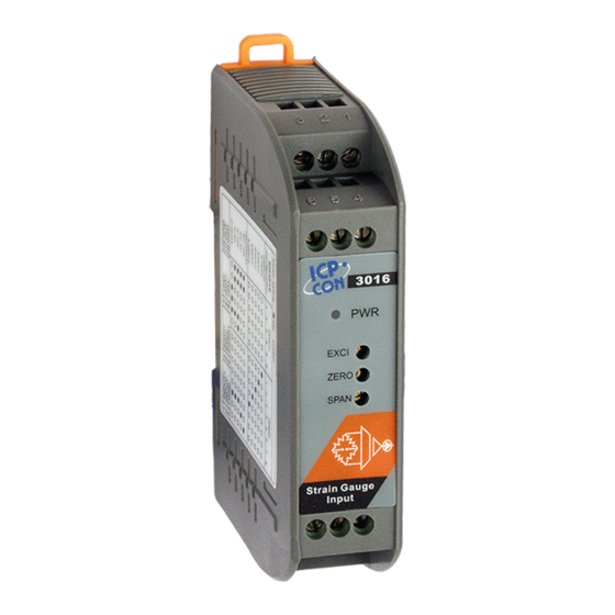
Introduction
The SG-3016 is a voltage input to voltage or current output signal conditioning module. It has
3000Vdc three-way isolation for input, output and power. And can change the input/output
range via internal configuration switches.
The SG-3016 has an LED display to show whether the SG-3016 is functioning correctly and
has three VRs (Zero, Span, Exci) to calibrate the input/output range accuracy.
The bandwidth of the SG-3016 is typically 600Hz. It's easy to mount the SG-3016 on a
standard DIN rail and can operate in environments with wide temperature range.
Specifications
Voltage Specifications:
Electrical input: ±10mV, ±20mV, ±30mV, ±50mV, ±100mV
Excitation voltage: 1 ~10Vdc (20mA max.)
Voltage output:
Bipolar: ±5V, ±10V
Unipolar: 0~5V, 0~10V
Output impedance: <50Ω
Current output:
Current: 0~20mA
Current load resistor:0~500Ω (Source)
General
Three-way isolation: 3000Vdc
Accuracy: ±0.1% of full range
Bandwidth: 600Hz (typical)@-3dB
Operation temperature range:-25°C~75°C
Storage temperature range:-30°C~85°C
Supply Voltage
Input Range: 10~30Vdc
Consumption: 1.44W (voltage output)
1.74W (current output)
configure
The terminal wiring for the SG-3016 is shown in Figure A. Positive power terminals pin's 7 and
9 are internally connected, as are negative pins 10 and 12. Power can be connected through
the adjacent modules, making wiring much easier. The SG-3016 uses a power input range of
10~30Vdc.
Table 1 and table 2 show the switch positions used to configure the input and output range.
The I/O configuration switches are located inside the module. And can be accessed by
removing the DIN-rail bracket covers by sliding them in the direction shown in Figure B.
SG-3016 Isolated Strain Gauge Input Module
User's Manual
Ver1.3,05/18/2005,~1~
Advertisement

Subscribe to Our Youtube Channel
Related Manuals for ICP DAS USA SG-3016


Summary of Contents for ICP DAS USA SG-3016
- Page 1 1.74W (current output) configure The terminal wiring for the SG-3016 is shown in Figure A. Positive power terminals pin’s 7 and 9 are internally connected, as are negative pins 10 and 12. Power can be connected through the adjacent modules, making wiring much easier. The SG-3016 uses a power input range of 10~30Vdc.
- Page 2 SG3016 Range (SW1) Range (SW2) Range (SW2) SG3016 Output Range Input Range ±10V ◆ ◆ ◆ * ±10mV ◆ ◆ ◆ ◆ ±5V * ±20mV ◆ ◆ ◆ ◆ ◆ ◆ 0~10V ±30mV ◆ ◆ ◆ ◆ ◆ 0~5V ±50mV ◆...
- Page 3 Configuration of SW1 Configuration of SW2 1 Input:±10mV Voltage Output 2 Input:±20mV 3 Input:±30mV Current Output 4 Input:±50mV 5 Input:±100mV ON Unipolar Output 6 Internal Gain1 :0.5 OFF Bipolar Output ON Internal Gain2 :2 7 Internal Gain1 :1 OFF Internal Gain2 :1 8 Internal Gain1 :2 Configuration of SW1 and SW2 Table 3:...
-
Page 4: Calibration Procedure
Calibration Procedure 1. Refer to figure C to adjust the offset value. (1) Connect pin7 to the +24Vdc and connect pin 10 to GND. (2) Connect pin8 and pin 11 to the meter. (3) Use wire to connect pins 1 and 2. (4) Changing the SW1 and SW2 depends on your input/output range. - Page 5 (4) Changing the SW1 and SW2 depends on your input/output range. Watch the value of the meter and adjust the VR3 (SPAN) value to the maximum value of this range. 3. Refer to figure E to adjust the excitation voltage value. (1) Connect pin7 to the +24Vdc and connect pin 10 to GND.
Need help?
Do you have a question about the SG-3016 and is the answer not in the manual?
Questions and answers