
Subscribe to Our Youtube Channel
Related Manuals for ICP DAS USA ET-7000/PET-7000 Series


Summary of Contents for ICP DAS USA ET-7000/PET-7000 Series
- Page 1 ET-7000/PET-7000 AIO series User Manual Service and usage information for ET-7005/PET-7005 ET-7015/PET-7015 ET-7017/PET-7017 ET-7017-10/PET-7017-10 ET-7018Z/PET-7018Z ET-7019/PET-7019...
- Page 2 Warranty All products manufactured by ICP DAS are under warranty regarding defective materials for a period of one year, beginning from the date of delivery to the original purchaser. Warning ICP DAS assumes no liability for any damage resulting from the use of this product.ICP DAS reserves the right to change this manual at any time without notice.
-
Page 3: Table Of Contents
Table of Contents Chapter 1. Introduction..............7 1.1. ET-7000/PET-7000 Family ..............8 1.1.1. PET-7000/ET-7000 Module Naming Convention ..........9 1.1.2. PET-7000/ET-7000 Comparison................ 10 1.2. Features...................12 1.3. Specification..................15 1.3.1. System Specification ..................15 1.3.2. I/O Specification....................17 1.3.2.1. PET-7005/ET-7005 ................17 1.3.2.2. - Page 4 2.3. Connecting to Network, PC and Power ........39 2.4. Installing the MiniOS7 Utility ............40 2.5. Using MiniOS7 Utility to Assign a New IP........41 2.6. Enabling Adobe Flash Player in Browser ........45 Chapter 3. Web Applications.............47 3.1.
- Page 5 3.4.1. Web HMI......................78 3.4.2. Web Edit ......................79 3.5. Pair Connection ................87 3.6. More Information ................88 Chapter 4. Modbus Applications ..........89 4.1. What is Modbus TCP/IP?..............90 4.2. Modbus Message Structure ............90 4.2.1. Address ......................91 4.2.2.
- Page 6 5.4. Uploading the ET-7000/PET-7000 Firmware .......139 Chapter 6. External Tools and Tasks........144 6.1. LabVIEW ..................144 6.2. OPC Server..................145 6.3. SCADA ...................146 6.3.1. InduSoft ......................147 6.3.2. Citect ....................... 148 6.3.3. iFix........................149 Appendix A. Node Information Area........150 ...
-
Page 7: Chapter 1. Introduction
Chapter 1. Introduction The PET-7000/ET-7000, a web-based Ethernet I/O module, features a built-in web server, which allows configuration, I/O monitoring and I/O control by simply using a regular web browser. Besides, with the web HMI function, no more programming or HTML skills are needed;... -
Page 8: 7000/Pet-7000 Family
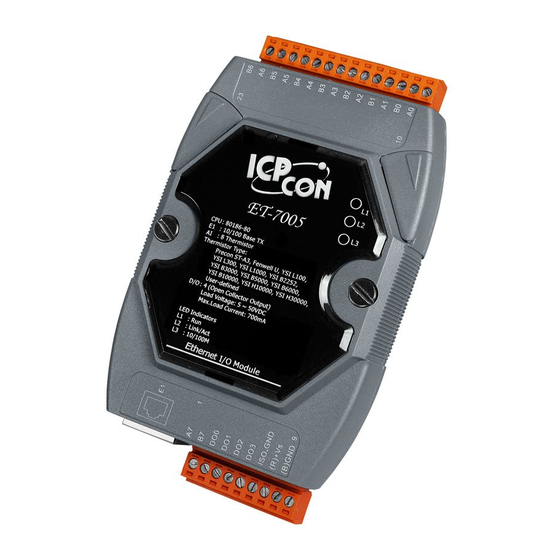
1.1. ET-7000/PET-7000 Family Either ET-7000 or PET-7000 has released three different types of analog series modules, which provides a variety of analog module choice, listed in the following table. Type Model Description PET-7005/ 8-channel Thermistor inputs and Thermistor ET-7005 4-channel digital outputs PET-7015/ 7-channel RTD Inputs with 3-wire RTD ET-7015... -
Page 9: Pet-7000/Et-7000 Module Naming Convention
1.1.1. PET-7000/ET-7000 Module Naming Convention As you examine this manual, you’ll notice there are many different products available. Sometimes it is difficult to remember the specifications for any given product. The figure below shows how the module naming conventions work for each PET-7000/ET-7000 product, you can take a few minutes to understand the module naming conventions, and it may save you sometime and confusion. -
Page 10: Pet-7000/Et-7000 Comparison
1.1.2. PET-7000/ET-7000 Comparison The features of the PET-7000 differ from the ET-7000 Power over Ethernet + ET-7000 = PET-7000 PET-7000 features “PoE” and many other advantages in ET-7000. Now, not only data but power is carried through an Ethernet cable. This feature makes installation of PET-7000 a piece of cake. - Page 11 More information about PET-7000 There are two ways for PET-7000 getting the power. One is through Ethernet by a PoE switch; the other is as usual through wiring by an external power. External power should range from +12 ~ 48 VDC. The reason we keep the second way is because it might be useful if someday or somehow you have different applications.
-
Page 12: Features
1.2. Features Built in Web Server Each PET-7000/ET-7000 module has a built-in web server that allows users to easily configure, monitor and control the module from a remote location using a regular web browser. Web HMI The Web HMI function allows the users to create dynamic and attractive web pages to monitor and control the I/O points. - Page 13 Communication Security Account and password are required when logging into the PET-7000/ET-7000 web server. An IP address filter is also included, which can be used to allow or deny connections with specific IP addresses. Modbus Protocol The Modbus/TCP slave function on the Ethernet port can be used to provide data to remote SCADA software.
- Page 14 Built-in Dual Watchdog The Dual Watchdog consists of a Module Watchdog and a Host Watchdog. Module Watchdog is a built-in hardware circuit that can be used to monitor the operation of the module and will reset the CPU module if a failure occurs in the hardware or the software.
-
Page 15: Specification
1.3. Specification 1.3.1. System Specification System 80186 CPU (80 MHz) 512 KB SRAM 512 KB Flash Memory 16 KB EEPROM Dual Watchdog Communication 10/100 Base-TX (With Link, Activity LED Indicator) Ethernet Port Automatic MDI/MDI-X Isolation Ethernet 2500 V LED Display PoE On (for PET-7000 series only) Run indicator... - Page 16 Power Requirements (for ET-7000 series only) Power reverse polarity protection Protection +10 V ~ +30 V (non-regulated) Required Supply Voltage 0.10 A @ 24 V Max. Power Consumption Power Requirements (for PET-7000 series only) Class 1 IEEE 802.3af Powered by Power-Over-Ethernet (PoE) or Required Supply Voltage external +12~ 48 V (non-regulated)
-
Page 17: I/O Specification
1.3.2. I/O Specification 1.3.2.1. PET-7005/ET-7005 ET-7000/PET-7000 AIO Series User Manual, version 1.0.1 beta3 Page: 17 Copyright © 2009 ICP DAS Co., Ltd. All Rights Reserved. E-mail: service@icpdas.com... - Page 18 Analog Input 8 (Differential) Input Channels Precon ST-A3, Fenwell U, YSI L100, Input Type YSI L300, YSI L1000, YSI B2252, YSI B3000, YSI B5000, YSI B6000, YSI B10000, YSI H10000, YSI H30000, User-defined 16-bit Resolution 8 Samples/second (Total) Sampling Rate +/- 0.01 % or better Accuracy +/- 10 μ...
-
Page 19: Pet-7015/Et-7015
1.3.2.2. PET-7015/ET-7015 ET-7000/PET-7000 AIO Series User Manual, version 1.0.1 beta3 Page: 19 Copyright © 2009 ICP DAS Co., Ltd. All Rights Reserved. E-mail: service@icpdas.com... - Page 20 Analog Input 7 (Differential) Input Channels Input Type 2/3 wire Wire Connection Pt100, Pt1000, Ni120, Cu100, RTD Type Cu1000 16-bit Resolution 12 Samples/second (Total) Sampling Rate +/- 0.05 % Accuracy 15.7 Hz -3dB Bandwidth +/- 0.5 μ V/°C Zero drift +/- 20 μ...
-
Page 21: Pet-7017/Et-7017
1.3.2.3. PET-7017/ET-7017 ET-7000/PET-7000 AIO Series User Manual, version 1.0.1 beta3 Page: 21 Copyright © 2009 ICP DAS Co., Ltd. All Rights Reserved. E-mail: service@icpdas.com... - Page 22 Analog Input 8 (Differential) Input Channels +/- 150 mV, +/- 500 mV, +/- 1 V, +/- 5V, Input Type +/- 10 V, +/- 20 mA, 0 ~ 20 mA, 4 ~ 20 mA (jumper selectable) 16-bit (Normal Mode) /12-bit (Fast Mode) Resolution 10 Samples/second (Normal Mode) / Sampling Rate...
-
Page 23: Pet-7017-10/Et-7017-10
1.3.2.4. PET-7017-10/ET-7017-10 ET-7000/PET-7000 AIO Series User Manual, version 1.0.1 beta3 Page: 23 Copyright © 2009 ICP DAS Co., Ltd. All Rights Reserved. E-mail: service@icpdas.com... - Page 24 Analog Input 10 differential or 20 single-ended (Note 1), Input Channels software selectable +/- 150 mV, +/- 500 mV, +/- 1 V, +/- 5 V, Input Type +/- 10 V, +/- 20 mA, 0 ~ 20 mA, 4 ~ 20 mA (jumper selectable) 16-bit (Normal Mode) /12-bit (Fast Mode) Resolution...
-
Page 25: Pet-7018Z/Et-7018Z
1.3.2.5. PET-7018Z/ET-7018Z ET-7000/PET-7000 AIO Series User Manual, version 1.0.1 beta3 Page: 25 Copyright © 2009 ICP DAS Co., Ltd. All Rights Reserved. E-mail: service@icpdas.com... - Page 26 Analog Input 10 (Differential) Input Channels +/- 15 mV, +/- 50 mV, +/- 100 mV, +/- 500 Input Type +/- 1 V, +/- 2.5 V, +/- 20 mA, 0 ~ 20 mA, 4 ~ 20 mA (Requires Optional External 125 Ohm Resistor) Thermocouple (J, K, T, E, R, S, B, N, C, L, M, LDIN43710)
-
Page 27: Pet-7019/Et-7019
1.3.2.6. PET-7019/ET-7019 ET-7000/PET-7000 AIO Series User Manual, version 1.0.1 beta3 Page: 27 Copyright © 2009 ICP DAS Co., Ltd. All Rights Reserved. E-mail: service@icpdas.com... - Page 28 Analog Input 8 (Differential) Input Channels +/- 15 mV, +/- 50 mV, +/- 100 mV, +/- 500 Input Type +/- 1 V, +/- 5 V, +/- 10V, +/- 20 mA, 0 ~ 20 4 ~ 20 mA (Jumper selectable) Thermocouple (J, K, T, E, R, S, B, N, C, L, M, LDIN43710) 16-bit Resolution...
-
Page 29: Overview
1.4. Overview Here is a brief overview of the components and its descriptions for module status. 1.4.1. Front Panel The PET-7000/ET-7000 front panel contains the Ethernet port, connectors and LEDs. J1 Connector (Pin 1 ~ 9) LED Indicators PoE LED Indicator (for PoE series only) J2 Connector (Pin 10 ~ 23) - Page 30 J1 Connector Depending on the types of the PET-7000/ET-7000 modules. For more detailed information regarding the pin assignments of the J1 Connector, please refer to “1.3.2. I/O Specification” J2 Connector Depending on the types of the PET-7000/ET-7000 modules. For more detailed information regarding the pin assignments of the J2 Connector, please refer to “1.3.2.
- Page 31 LED Indicators Name LED Action Function Flashing Firmware is running Ethernet link detected Link/ACT No Ethernet link detected Flashing Green Ethernet packet received Speed 10 Mbps 10/100M Orange Speed 100 Mbps Tips & Warnings If the Run LED does not display the information as above, the following steps should be taken: Step 1: Switch the power off Step 2: Check that the Init/Normal switch is in the Normal position...
-
Page 32: Back Panel
1.4.2. Back Panel The PET-7000/ET-7000 back panel contains the frame ground and operating mode selector switch. Operating Mode Frame Ground S it h ET-7000/PET-7000 AIO Series User Manual, version 1.0.1 beta3 Page: 32 Copyright © 2009 ICP DAS Co., Ltd. All Rights Reserved. E-mail: service@icpdas.com... - Page 33 Operating Mode Selector Switch Init mode: MiniOS7 configuration mode Normal mode: Firmware running mode In the PET-7000/ET-7000 series, the Switch is always in the Normal position. Only when updating the PET-7000/ET-7000 firmware or OS, the switch can be moved from the Normal position to the Init position.
-
Page 34: Dimensions
1.5. Dimensions All dimensions are in millimeters. ET-7000/PET-7000 AIO Series User Manual, version 1.0.1 beta3 Page: 34 Copyright © 2009 ICP DAS Co., Ltd. All Rights Reserved. E-mail: service@icpdas.com... -
Page 35: Companion Cd
1.6. Companion CD This package comes with a CD that provides drivers, software utility, all of the required documentations…, etc. All of them are listed below. ET-7000/PET-7000 AIO Series User Manual, version 1.0.1 beta3 Page: 35 Copyright © 2009 ICP DAS Co., Ltd. All Rights Reserved. E-mail: service@icpdas.com... -
Page 36: Chapter 2. Getting Started
Chapter 2. Getting Started If you are a new user, begin with this chapter, it includes a guided tour that provides a basic overview of installing, configuring and using the ET-7000/PET-7000. 2.1. Mounting the Hardware The ET-7000/PET-7000 can be mounted with the bottom of the chassis on the DIN rail, the wall or piggyback. - Page 37 Din Rail Mountable Model Three Din rail mountable models are available to mount a variety of ICP DAS devices. Each is made of stainless steel and has a ground wire at the end. Part number Maximum number of Dimensions modules 125 mm x 35 mm DRS-125 240 mm x 35 mm...
-
Page 38: Configuring The Boot Mode
2.2. Configuring the Boot Mode The ET-7000/PET-7000 has two operating modes that can be determined by the switch mechanism on the chassis. Init Mode Init mode is a way to use MiniOS7 configuration mode. Init Normal Normal Mode Normal mode is the default mode of operation and the one you will use most of the time. -
Page 39: Connecting To Network, Pc And Power
2.3. Connecting to Network, PC and Power The ET-7000/PET-7000 is equipped with an RJ-45 Ethernet port for connection to an Ethernet hub/switch and PC Non-PoE ET-7000/PET-7000 AIO Series User Manual, version 1.0.1 beta3 Page: 39 Copyright © 2009 ICP DAS Co., Ltd. All Rights Reserved. E-mail: service@icpdas.com... -
Page 40: Installing The Minios7 Utility
2.4. Installing the MiniOS7 Utility The MiniOS7 Utility is a useful tool that provides a quick and easy way to update OS image or firmware, configure Ethernet settings, and download files to ET-7000/PET-7000 from PC. Step 1: Get the MiniOS7 Utility tool The MiniOS7 Utility can be obtained from companion CD or our FTP site: CD:\Napdos\minios7\utility\minios7_utility\ ftp://ftp.icpdas.com/pub/cd/8000cd/napdos/minios7/utility/minios7_utility/... -
Page 41: Using Minios7 Utility To Assign A New Ip
2.5. Using MiniOS7 Utility to Assign a New IP The ET-7000/PET-7000 are web-based devices, which comes with a default IP address, therefore, you must first assign a new IP address to the ET-7000/PET-7000. The factory default IP settings are as follows: Item Default 192.168.255.1... - Page 42 Step 2: Press “F12” or choose “Search” from the “Connection” menu After pressing F12 or choosing Search from Connection menu, that will search all of the MiniOS7 modules on your network. See the status tip, waiting for the search to be done. Step 3: Choose the field “192.168.255.1”...
- Page 43 Step 4: Assign a new IP address and then choose “Set” button You can manually assign an IP address or use DHCP to dynamically assign IP addresses Step 5: Choose “Yes” button After completing the settings, the Confirm dialog box will appear, and then choose the Yes button to exit the procedure.
- Page 44 Step 6: Reboot the module and then press “F12” or choose “Search” from the “Connection” menu to check the IP setting After completing the settings, you can reboot the module and then using MiniOS7 to search module again for making sure that your IP settings are correct.
-
Page 45: Enabling Adobe Flash Player In Browser
2.6. Enabling Adobe Flash Player in Browser Your browser must support the Adobe Flash Player in order to view the ET-7000/PET-7000 web site. If you do not have it installed, please follow the instructions below. Step 1: Go to the Adobe Flash Player Download Center The Adobe Flash Player Download Center: http://get.adobe.com/flashplayer/ Step 2: Follow the prompts to download the installation file... - Page 46 Step 3: Verify that the Adobe Flash Player has been installed You can verify that it has been installed correctly by clicking the link below. http://get.adobe.com/flashplayer/completion/dlm/ ET-7000/PET-7000 AIO Series User Manual, version 1.0.1 beta3 Page: 46 Copyright © 2009 ICP DAS Co., Ltd. All Rights Reserved. E-mail: service@icpdas.com...
-
Page 47: Chapter 3. Web Applications
Chapter 3. Web Applications The ET-7000/PET-7000 contains an advanced web configuration system that provides users with access ET-7000/PET-7000 applications through a standard web browser. Logging in to the ET-7000/PET-7000 Web site You can log in to the ET-7000/PET-7000 web site from any computer that has Internet access. - Page 48 Step 3: Fill out the User name and Password After entering the IP address, the login dialog box will appear and prompt you to enter your username and password. The factory default user name and password are as follows: Item Default User name Admin...
- Page 49 Step 4: Welcome to ET-7000/PET-7000 web site After logging into the ET-7000/PET-7000 web site, the welcome page will appear. This site serves several functions. You can easily access these functions through the menu on the left side. The Overview of the Main menu provides a brief introduction and explanation of this site.
-
Page 50: Overview
3.1. Overview The Overview links to the welcome page that determines two message body parts. ET-7000/PET-7000 AIO Series User Manual, version 1.0.1 beta3 Page: 50 Copyright © 2009 ICP DAS Co., Ltd. All Rights Reserved. E-mail: service@icpdas.com... - Page 51 The first part of this page provides basic information about the ET-7000/PET-7000 hardware and software. The second part of this page provides a brief introduction of this web site. ET-7000/PET-7000 AIO Series User Manual, version 1.0.1 beta3 Page: 51 Copyright © 2009 ICP DAS Co., Ltd. All Rights Reserved. E-mail: service@icpdas.com...
-
Page 52: Configuration
3.2. Configuration All items below are located under the Configuration menu: Network Settings: Links to the Ethernet Settings page that allows you to access th e IP settings and check the software version. asic Settings: Links to the Basic Settings page that allows you to configure the basic information of this site. -
Page 53: Network Settings
3.2.1. Network Settings The Ethernet Settings page provides the following functions: Configure the network settings Check the software information ET-7000/PET-7000 AIO Series User Manual, version 1.0.1 beta3 Page: 53 Copyright © 2009 ICP DAS Co., Ltd. All Rights Reserved. E-mail: service@icpdas.com... -
Page 54: Configure The Network Settings
3.2.1.1. Configure the Network Settings A generally network setting includes the following parameters: IP address: Each device including PET-7000/ET-7000 on the network must have a unique IP address. It is used to assign the unique IP address. Gateway address: The address of the gateway server on the network. ... - Page 55 Manually Configuration In manual configuration, you have to assign all the network settings manually. To configure network settings manually, follow the following steps: Step 1: Disable the DHCP Step 2: Enter the network settings Step 3: Click MODIFY_SETTING to save the network settings ET-7000/PET-7000 AIO Series User Manual, version 1.0.1 beta3 Page: 55 Copyright ©...
-
Page 56: Check The Software Information
3.2.1.2. Check the software information The software information includes the following data items: Web Server Lib Ver.: The version of the web server library. The web server library is a collection of web development solutions. MiniOS7 Ver.: The version of the MiniOS7 OS image. The MiniOS7 is an ... -
Page 57: Basic Settings
3.2.2. Basic Settings The Basic Settings page provides the following functions: Configure the module information Configure the web site information Reset all settings to default ET-7000/PET-7000 AIO Series User Manual, version 1.0.1 beta3 Page: 57 Copyright © 2009 ICP DAS Co., Ltd. All Rights Reserved. E-mail: service@icpdas.com... -
Page 58: Configure The Module Information
3.2.2.1. Configure the Module Information The module information includes the following data items: Module Name: The name of the module that can be modified. It has an initial value depending on the name of the module. Module Information: The module information indicates the name of the alias that ... -
Page 59: Configure The Web Site Information
3.2.2.2. Configure the Web site Information The module information includes the following data items: Top page Information (First line) and Top page Information (Second line): The title of the website that can be modified, you can view the title information in the top-left corner. - Page 60 Web Server TCP Port: A port number of the TCP/IP port. A port number is a 16-bit unsigned integer. By default, TCP/IP uses port 80. To configure the web site information, follow the following steps: Step 1: Enter the web site information Step 2: Click Submit to save the module information ET-7000/PET-7000 AIO Series User Manual, version 1.0.1 beta3 Page: 60...
-
Page 61: Reset All Settings To Default
3.2.2.3. Reset All Settings to Default According to the menu selection of this web, the reset function can be divided into the following categories. You can use this function to reset the settings to their factory default. Configuration Authentication ... -
Page 62: Factory Default Settings For Configuration Menu Service
3.2.2.3.1. Factory Default Settings for Configuration Menu Service The table below lists the factory default settings of the configuration menu. Network Settings Data Item Factory Default Settings 192.168.255.1 192.168.0.1 Gateway 255.255.0.0 Mask Disable DHCP Basic Settings Data Item Factory Default Settings Depending on the module name Module Name Empty... - Page 63 Module I/O Settings PET-7017/ET-7017 and the ET-7017-10 Modbus Settings (Common Functions) CPU reset events Set Host Watchdog Timer CPU reset status CPU reset events Set Host Watchdog Timer Host WDT events Modbus Address Modbus NetID Digital Output Power Value Safe Value Modbus Settings (AI Basic Setting) Type 60, PreCon Type III, -30°F to 240...
- Page 64 Value of All AI Channels Low Alarm Value for Average Value of All AI Channels PET-7015/ET-7015 Modbus Address Modbus NetID Modbus Settings (AI Basic Setting) 20, +/- 100 ˚C, Pt 100, α=0.00385 Analog Input Range Enable OFF (60 Hz rejection) 50/60 Hz rejection for AI OFF (Hex) AI Data Format...
- Page 65 PET-7017/ET-7017 and the ET-7017-10 Modbus Address Modbus NetID Digital Output Power Value Safe Value Modbus Settings (AI Basic Setting) 08 (+/- 10 V) Analog Input Range Enable OFF (60 Hz rejection) 50/60 Hz rejection for AI OFF (Hex) AI Data Format Normal Input Mode Modbus Settings (AI High/Low Alarm Setting)
- Page 66 PET-7018Z/ET-7018Z Modbus Address Modbus NetID Digital Output Power Value Safe Value Modbus Settings (AI Basic Setting) 05 (+/- 2.5 V) Analog Input Range Enable OFF (60 Hz rejection) 50/60 Hz rejection for AI OFF (Hex) AI Data Format CJC Total Offset Start CJC Update Setting CJC Offset...
- Page 67 ET-7019/PET-7019 Modbus Address Modbus NetID Digital Output Power Value Safe Value Modbus Settings (AI Basic Setting) 05 (+/- 2.5 V) Analog Input Range Enable OFF (60 Hz rejection) 50/60 Hz rejection for AI OFF (Hex) AI Data Format CJC Total Offset Start CJC Update Setting CJC Offset...
-
Page 68: Factory Default Settings For Authentication Menu Service
3.2.2.3.2. Factory Default Settings for Authentication Menu Service Account Management Factory Default Setting A default user account consists of a account name “Admin” and a password “Admin”. Accessible IP Settings Factory Default Setting Empty, there is no IP limit on incoming terminals. 3.2.2.3.3. -
Page 69: Module I/O Settings
3.2.3. Module I/O Settings Module I/O settings page includes Common Functions settings and particular I/O settings such as Power-on, safe value, enable/disable I/O channels. On the page the Modbus address mapping of each function is also listed for easy checking and using. The illustration below shows the Modbus settings for the ET-7019 module This page display different contents depending on the Modbus function of the ET-7000/PET-7000 module. -
Page 70: Authentication
3.3. Authentication All items below are located under the Authentication menu: Account Management: Links to the Privilege management page that allows you to manage the user accounts and their privileges. Accessible IP Settings: Links to the IP filter Settings page that allow you to control access privileges by filtering IP address. -
Page 71: Account Management
3.3.1. Account Management The Basic Settings page provides the following functions: Configure the user accounts Load the factory default user account ET-7000/PET-7000 AIO Series User Manual, version 1.0.1 beta3 Page: 71 Copyright © 2009 ICP DAS Co., Ltd. All Rights Reserved. E-mail: service@icpdas.com... -
Page 72: Configure The User Accounts
3.3.1.1. Configure the user accounts The PET-7000/ET-7000 web site supports up to 5 user accounts. A built-in administrator account The built-in Administrator is basically a setup and disaster recovery account that can be deleted. You can change the administrator account’s password. Four user-defined account ... -
Page 73: Load The Factory Default User Accounts
3.3.1.2. Load the factory default user accounts The PET-7000/ET-7000 has a built-in administrator account named Admin which is created when it is installed by default. The default account cannot be deleted. Step 1: Select the Load Setup Default checkbox Step 2: Click Submit to finished configuring the user accounts ET-7000/PET-7000 AIO Series User Manual, version 1.0.1 beta3 Page: 73 Copyright ©... -
Page 74: Accessible Ip Settings
3.3.2. Accessible IP Settings The IP filter Settings page provides the following functions: Configure connection filtering ET-7000/PET-7000 AIO Series User Manual, version 1.0.1 beta3 Page: 74 Copyright © 2009 ICP DAS Co., Ltd. All Rights Reserved. E-mail: service@icpdas.com... -
Page 75: Configuring Ip Filter
3.3.2.1. Configuring IP filter The PET-7000/ET-7000 with an IP filter that enables you to restrict or grant user access based an IP filter list you create. The filter can be enabled or disable by selecting the Enable the IP filter table checkbox Tips &... - Page 76 Method 1: Allows access from a single IP address Step 1: Select the Enable the IP filter table checkbox Step 2: Enter the same IP address in the From (IP Address) and To (IP Address) Step 3: Select the Active the rule checkbox Step 4: Click Submit to finished configuring the IP filter list Method 2: Allow access from a group of IP addresses Step 1: Select the Enable the IP filter table checkbox...
-
Page 77: Web Hmi
3.4. Web HMI All items below are located under the Web HMI menu: Web HMI: Links to the I/O monitor page that allows you to monitor the Web Edit: Links to the Web Page Configuration page that allows you to ET-7000/PET-7000 AIO Series User Manual, version 1.0.1 beta3 Page: 77 Copyright ©... -
Page 78: Web Hmi
3.4.1. Web HMI By default, this page displays summary information about I/O channels which are classified according to the module type. Here you can add more tabs and set the starting tab by editing the web edit page, for more details, please refer to 3.4.2. Web Edit. ET-7000/PET-7000 AIO Series User Manual, version 1.0.1 beta3 Page: 78 Copyright ©... -
Page 79: Web Edit
3.4.2. Web Edit The Web Editing page provides functions to create the user-defined web pages which are displayed on the Web HMI page. Web HMI page By default, there are no pages to be listed in the Web Page Configuration form. ET-7000/PET-7000 AIO Series User Manual, version 1.0.1 beta3 Page: 79 Copyright ©... - Page 80 The ET-7000/PET-7000 supports up to 10 user-defined web pages A maximum of 10 pages can be created. Below is an example of how to create your own page. ET-7000/PET-7000 AIO Series User Manual, version 1.0.1 beta3 Page: 80 Copyright © 2009 ICP DAS Co., Ltd. All Rights Reserved. E-mail: service@icpdas.com...
- Page 81 Example: Create a Web page to monitor the I/O of the conveyer system shown below. The I/O system contains a sensor that are used to detect the products, and a switch that are used to turn the conveyer motor on and off. Step 1: Add a new page Click Add new Page Step 2: Upload a diagram...
- Page 82 Click Browse… to select an image, and then click Upload to upload images to the ET-7000/PET-7000 module. 1. Click Browse… to select an image 2. Click Upload to upload the image Tips & Warnings The file type of images can be either of .jpg, .gif, or .bmp. The recommended resolution for the image to be displayed on the editing Web page is 340 * 250 pixels.
- Page 83 Type the page name in the Page Name field and then select the diagram from the Image list box. (After selecting the diagram, the diagram will be shown in the Preview window) Step 4: Add the register item for reading selected sensor input Click Edit in the first row of the Group table and then the Edit Group Register window will be displayed.
- Page 84 Step 5: Add a DI for reading PHS1 input Set PHS1 to be an input, you can using the Modbus Register 1, then select Discrete Input as the Register Type and type PHS as the Alias. Step 6: Save selected sensor settings Click Save button to complete set up Step 7: Add the register item for writing selected motor output to turn/ After save the register settings, the new register item will be displayed in the Group table.
- Page 85 Step 8: Add a DO for writing Motor1 output to turn the conveyer motor on and off Set Motor to be an output, you can using the Modbus Register 1, then select Coil as the Register Type and type Motor as the Alias. Step 9: Save selected sensor settings Click Save button to complete set up Step 10: Save the editing page.
- Page 86 Step 11: Browse the Conveyer web page. After saving the editing page, the editing page named as Conveyer has been added to the list box on the top-left hand side of the Web Page Configuration window. Then select the Conveyer item and click Go to browse to the Conveyer web page.
-
Page 87: Pair Connection
3.5. Pair Connection The Pair Connection links to the configuration page of the pair connection function. This pair connection function is a particular feature of ET-7000/PET-7000 that can enable a pair of DI-to-DO via Modbus/TCP (Ethernet). ET-7000/PET-7000 AIO Series User Manual, version 1.0.1 beta3 Page: 87 Copyright ©... -
Page 88: More Information
3.6. More Information The More Information links to the ET-7000/PET-7000 web site that provides more detailed information related to ET-7000/PET-7000 series products. You can change the URL of this link by simply editing the URL, for more details, please refer to section “3.2.2.2. -
Page 89: Chapter 4. Modbus Applications
Chapter 4. Modbus Applications The ET-7000/PET-7000 is a Modbus device that allows you to access terminals data via Ethernet and communicates using a master-slave technique in which only one device (the master) can initiate transactions (called queries). The other devices (slaves) respond by supplying the requested data to the master, or by taking the action requested in the query. -
Page 90: What Is Modbus Tcp/Ip
4.1. What is Modbus TCP/IP? Modbus is a communication protocol developed by Modicon in 1979. Different versions of Modbus used today include Modbus RTU (based on serial communication like RS485 and RS232), Modbus ASCII and Modbus TCP, which is the Modbus RTU protocol embedded into TCP packets. -
Page 91: Address
4.2.1. Address The first byte of information in the message structure of Modbus is the receiver’s address. The valid addresses are in the range of 0 to 247. Addresses from 1 to 247 are given to individual Modbus devices and 0 is used for broadcast. Reference Description Read/Write Discrete Outputs or Coils. -
Page 92: Function Codes
4.2.2. Function Codes The second byte in the frame structure is the function code. The function code describes what the slave is required to do. Valid function codes are between 1 and 255. The slave uses the same function code as the request to answer it. Only when error occurs in the system, the highest bit of the function code will be made ‘1’. -
Page 93: Modbus Register Map
4.3. Modbus Register Map 4.3.1. Common Function (0xxxx) DO address Begin Registers Access Points Description Range address per Point Type Recover all I/O default 1=recover settings (Pulse) Reboot 1=reboot ET-7000/PET-7000 (Pulse) (3xxxx) AI address Begin Registers Access Points Description Range address... - Page 94 (4xxxx) AO address Begin Registers Access Points Description Range address per Point Type 1= by power on 2= by 0.8 second WDT CPU reset status 3= by Reset command How many CPU reset events has happened? When CPU is reset by one CPU reset events R/W/E of the situations described...
-
Page 95: Particular Function
4.3.2. Particular Function ET-7000/PET-7000 AIO Series User Manual, version 1.0.1 beta3 Page: 95 Copyright © 2009 ICP DAS Co., Ltd. All Rights Reserved. E-mail: service@icpdas.com... -
Page 96: Pet-7005/Et-7005 I/O Address Mapping
4.3.2.1. PET-7005/ET-7005 I/O Address Mapping Modbus Address (Base 0) 30000 30001 30002 AI Channel (Base 0) 30003 30004 30005 30006 30007 00000 00001 DO Channel (Base 0) 00002 00003 ET-7000/PET-7000 AIO Series User Manual, version 1.0.1 beta3 Page: 96 Copyright © 2009 ICP DAS Co., Ltd. All Rights Reserved. E-mail: service@icpdas.com... - Page 97 Detailed Modbus Address Table for ET-7005/PET-7005 (D) (0xxxx) DO address Begin Point Registers Access Description Range address per Point Type 0~31 0=off Digital Out (32) 1=on 32~161 Reserved 0~31 Clear AI Latch High (single) 1=clear (32) (Pulse) 0~31 Clear AI Latch Low (single) 1=clear (32) (Pulse)
- Page 98 (80) 1=on (Default=0) 0=disable 0~31 Enable/Disable AI channel 1=enable R/W/E (32) (Default=1) 0: F Temperature Scale 1: C R/W/E (Default=0) Reserved 1=50Hz 50/60Hz rejection for AI 0=60Hz R/W/E (Default=0) Reserved 0=hex AI data format 1=engineering R/W/E (Default=0) Return the factory calibration (All) 1=clear (Pulse) Reserved...
- Page 99 0=OK High Alarm of Average value of all 1=alarm AI channel (Pulse) (Clear) 0=OK Low Alarm of Average value of all 1=alarm AI channel (Pulse) (Clear) 0=disabled Enable/Disable Calibration 1=enabled Zero calibration channel 0 1=write (Pulse) Span calibration channel 0 1=write (Pulse) ...
- Page 100 (3xxxx) AI address Begin Registers Access Points Description Range address per Point Type 0~31 -32768 ~ Analog Input word (32) +32767 32~143 Reserved 0~65535 or 0~31 Average value of one channel word -32768 ~ (32) +32767 0~65535 or Average value of all enabled AI word -32768 ~ channel...
- Page 101 313~319 Reserved AI (channel number) word 0 ~ 16 321~349 Reserved 123 (hex) means OS image version word version=1.2.3 123 (hex) means Total firmware version word version=1.2.3 123 (hex) means CPU lib version word version=1.2.3 123 (hex) means I/O firmware version word version=1.2.3 123 (hex) means...
- Page 102 (4xxxx) AO address Begin Registers Access Points Description Range address per Point Type 0~58 Reserved Average times for every channel word 0 ~ 40 R/W/E 0~49 AO mapping address for external word 0x0000 ~ 0xffff R/W/E (50) Modbus devices 0~31 110~141 Temperature offset of channel...
- Page 103 the situations described in register 555, the event increases one count <5: Disable 5 ~ 65535: Set host watch dog timer word R/W/E Enable (Unit: second) Host watch dog events word 0 ~ 32767 16 ASCII Module name 4 word characters 16 ASCII Module nick name...
-
Page 104: Pet-7015/Et-7015 I/O Address Mapping
4.3.2.2. PET-7015/ET-7015 I/O Address Mapping Modbus Address (Base 0) 30000 30001 30002 AI Channel (Base 0) 30003 30004 30005 30006 ET-7000/PET-7000 AIO Series User Manual, version 1.0.1 beta3 Page: 104 Copyright © 2009 ICP DAS Co., Ltd. All Rights Reserved. E-mail: service@icpdas.com... - Page 105 Detailed Modbus Address Table for ET-7015/PET-7015 (D) (0xxxx) DO address Begin Registers Access Points Description Range address per Point Type 0=disable Enable/Disable AI channel 1=enable R/W/E (Default=1) 0=50Hz 50/60Hz rejection for AI 1=60Hz R/W/E (Default=1) 1=engineering AI data format 0=hex R/W/E (Default=0)
- Page 106 (3xxxx) AI address Begin Registers Access Points Description Range address per Point Type -32768 ~ Analog Input word +32767 (4xxxx) AO address Begin Registers Access Points Description Range address per Point Type Temperature offset word -128 ~ 127 R/W/E Modbus NetID word...
-
Page 107: Pet-7017/Et-7017 I/O Address Mapping
4.3.2.3. PET-7017/ET-7017 I/O Address Mapping Modbus Address (Base 0) 30000 30001 30002 AI Channel (Base 0) 30003 30004 30005 30006 30007 00000 00001 DO Channel (Base 0) 00002 00003 ET-7000/PET-7000 AIO Series User Manual, version 1.0.1 beta3 Page: 107 Copyright © 2009 ICP DAS Co., Ltd. All Rights Reserved. E-mail: service@icpdas.com... - Page 108 Detailed Modbus Address Table for ET-7017/PET-7017 (D) (0xxxx) DO address Begin Registers Access Points Description Range address per Point Type 0=off Digital Out 1=on Clear AI Latch High 1=clear (Pulse) Clear AI Latch Low 1=clear (Pulse) Enable the average value of the 0=disable previous AI values of one channel 1=enable...
- Page 109 (Default=0) 1=engineering AI data format 0=hex R/W/E (Default=0) Return the factory calibration (All) 1=clear R/W/E Clear AI Latch High (All) 1=clear (Pulse) Clear AI Latch Low (All) 1=clear (Pulse) 0=disabled AI Alarm High switch R/W/E 1=enabled 0=disabled AI Alarm Low switch R/W/E 1=enabled 0=Moment...
- Page 110 (3xxxx) AI address Begin Registers Access Points Description Range address per Point Type -32768 ~ Analog Input word +32767 -32768 ~ Average value of one channel word +32767 -32768 ~ Average value of all enabled AI channel word +32767 Average value of all maximum latched -32768 ~ word...
- Page 111 (4xxxx) AO address Begin Registers Access Points Description Range address per Point Type Average times for every channel word 0 ~ 40 R/W/E Enable/Disable AI channel word 0 ~ 65535 High alarm value for average 0 ~ 65535 or word R/W/E value of all AI channel...
-
Page 112: 7017-10 I/O Address Mapping
4.3.2.4. ET-7017-10 I/O Address Mapping Modbus Address (Base 0) 30000 30001 30002 AI Channel (Base 0) 30003 30004 30005 30006 30007 30008 30009 ET-7000/PET-7000 AIO Series User Manual, version 1.0.1 beta3 Page: 112 Copyright © 2009 ICP DAS Co., Ltd. All Rights Reserved. E-mail: service@icpdas.com... - Page 113 Detailed Modbus Address Table for ET-7017/PET-7017 (D) (0xxxx) DO address Begin Registers Access Points Description Range address per Point Type Clear AI Latch High 1=clear (Pulse) Clear AI Latch Low 1=clear (Pulse) Enable the average value of the 0=disable previous AI values of one 1=enable R/W/E...
- Page 114 0=Moment AI Alarm High mode R/W/E 1=Latched 0=Moment AI Alarm Low mode R/W/E 1=Latched 0=OK AI High Alarm 1=alarm (Clear) (Pulse) 0=OK AI Low Alarm 1=alarm (Clear) (Pulse) High Alarm of Average value of 0=OK all AI channel 1=alarm (Clear) (Pulse) Low Alarm of Average value of all 0=OK...
- Page 115 (4xxxx) AO address Begin Registers Access Points Description Range address per Point Type Average times for every channel word 0 ~ 40 R/W/E Enable/Disable AI channel word 0 ~ 65535 High alarm value for average 0 ~ 65535 or word R/W/E value of all AI channel...
-
Page 116: Pet-7018Z/Et-7018Z I/O Address Mapping
4.3.2.5. PET-7018Z/ET-7018Z I/O Address Mapping AI Channel Modbus address 30000 30001 30002 30003 30004 30005 30006 30007 30008 30009 DO Channel Modbus Address 00000 00001 00002 00003 00004 00005 ET-7000/PET-7000 AIO Series User Manual, version 1.0.1 beta3 Page: 116 Copyright © 2009 ICP DAS Co., Ltd. All Rights Reserved. E-mail: service@icpdas.com... - Page 117 Detailed Modbus Address Table for ET-7018Z/PET-7018Z (0xxxx) DO address Begin Registers Access Points Description Range address per Point Type 0=off Digital Out 1=on Clear AI Latch High 1=clear (Pulse) Clear AI Latch Low 1=clear (Pulse) Enable the average value of the 0=disable previous AI values of one channel 1=enable...
- Page 118 1=60Hz (default=1) 1=engineering AI data format 0=hex R/W/E (default=0) Return the factory calibration (all) 1=clear (Pulse) Clear AI Latch High (all) 1=clear (Pulse) Clear AI Latch Low (all) 1=clear (Pulse) 0=disabled high alarm AI Alarm High switch R/W/E 1=enabled high alarm 0=disabled low alarm AI Alarm Low switch...
- Page 119 Zero calibration channel 0 1 = write (Pulse) Span calibration channel 0 1=write (Pulse) (1xxxx) DI Address Begin Registers Access Points Description Range address per Point Type High alarm for the average value of 0=ok all AI registers 1=alarm Low alarm for the average value of 0=ok all AI registers...
- Page 120 (3xxxx) AI address Begin Registers Access Points Description Range address per Point Type -32768 ~ Analog Input word +32767 -32768 ~ CJC temperature word +32767 0 ~ 65535 or Average value of one channel word -32768 ~ +32767 0 ~ 65535 or Average value of all enabled AI channel word -32768 ~...
- Page 121 means version=1.2.3 123 (hex) I/O firmware version word means version=1.2.3 123 (hex) Xserver lib version word means version=1.2.3 123 (hex) TCP/IP lib version word means version=1.2.3 123 (hex) Modbus lib version word means version=1.2.3 123 (hex) Web lib version word means version=1.2.3 0= no error...
- Page 122 (4xxxx) AO address Begin Points Description Registers Range Access address per Point Type Average times for every word 0 ~ 40 R/W/E channel Enable/Disable AI channel word 0 ~ 65535 High alarm value for word 0 ~ 65535 or R/W/E average value of all AI -32768 ~ +32767...
-
Page 123: 7019 I/O Address Mapping
4.3.2.6. ET-7019 I/O Address Mapping Modbus Address (Base 0) 30000 30001 30002 AI Channel (Base 0) 30003 30004 30005 30006 30007 00000 00001 DO Channel (Base 0) 00002 00003 ET-7000/PET-7000 AIO Series User Manual, version 1.0.1 beta3 Page: 123 Copyright © 2009 ICP DAS Co., Ltd. All Rights Reserved. E-mail: service@icpdas.com... - Page 124 Detailed Modbus Address Table for ET-7019 (0xxxx) DO address Begin Registers Access Points Description Range address per Point Type 0=off Digital Out 1=on Clear AI Latch High 1=clear (Pulse) Clear AI Latch Low 1=clear (Pulse) Recover all I/O default settings 1=clear (Pulse) Reboot ET-7000...
- Page 125 1=fast (12 bit) (Default=0) 1=50Hz 50/60Hz rejection for AI 0=60Hz R/W/E (Default=0) 1=engineering AI data format 0=hex R/W/E (Default=0) Return the factory calibration (All) 1=clear R/W/E Clear AI Latch High (All) 1=clear (Pulse) Clear AI Latch Low (All) 1=clear (Pulse) 0=disabled AI Alarm High switch R/W/E...
- Page 126 (Pulse) Span calibration channel 0 1=Write (Pulse) (1xxxx) DI Address Begin Registers Access Points Description Range address per Point Type 0=Normal AI alarm high 1=Alarm 0=Normal AI alarm low 1=Alarm High alarm for the average value of 0=Normal all AI registers 1=Alarm Low alarm for the average value of 0=Normal...
- Page 127 (3xxxx) AI address Begin Registers Access Points Description Range address per Point Type Analog Input word -32768 ~ +32767 CJC data word -32768 ~ +32767 0 ~ 65535 or Average value of one channel word -32768 ~ +32767 Average value of all enabled AI 0 ~ 65535 or word channel...
- Page 128 (4xxxx) AO address Begin Registers Access Points Description Range address per Point Type Average times for every word 0 ~ 40 R/W/E channel Enable/Disable AI channel word 0 ~ 65535 High alarm value for average 0 ~ 65535 or word R/W/E value of all AI channel...
-
Page 129: Chapter 5. Minios7 Utility Tool
Chapter 5. MiniOS7 Utility Tool MiniOS7 Utility is a tool for uploading firmware to flash memory and updating the OS to ET-7000/PET-7000 module embedded with ICP DAS MiniOS7 with easiness and quickness. If you don’t have the MiniOS7 Utility installed on your system, installation of the MiniOS7 Utility should be the first step. - Page 130 Step 2: Press “F12” or choose “Search” from the “Connection” menu After pressing F12 or choosing Search from Connection menu, that will search all of the MiniOS7 modules on your network. See the status tip, waiting for the search to be done. Step 3: Double-Click the field of your ET-7000/PET-7000 module Double-Click the field of your ET-7000/PET-7000 module in...
- Page 131 Step 4: The connection has ready been established Check the connection status in the top right side to make sure the connection has been established Connection Status Disconnected Connected ET-7000/PET-7000 AIO Series User Manual, version 1.0.1 beta3 Page: 131 Copyright © 2009 ICP DAS Co., Ltd. All Rights Reserved. E-mail: service@icpdas.com...
-
Page 132: Exchanging The Protocol (Tcp/Ip To Udp)
5.2. Exchanging the Protocol (TCP/IP to UDP) MiniOS7 Utility supports both UDP and TCP protocols. For MiniOS7 Utility, the TCP/IP is the default protocol for communicating with ET-7000/PET-7000, and the UDP is used to update the OS. Therefore, if you want to update the OS, you might need to change protocols to support them. - Page 133 Step 3: Click “Yes” to continue After executing the Quick Firmware command, the Confirm dialog will appear, and then click Yes button to continue and stop the firmware running. Step 4: Click “Yes” to continue After confirming the command, the Confirm dialog will appear, and then click Yes button to exchange UDP protocol for TCP protocol.
-
Page 134: Updating The Et-7000/Pet-7000 Os
5.3. Updating the ET-7000/PET-7000 OS ICP DAS will continue to add additional features to ET-7000/PET-7000 OS in the future, so we advise you to periodically check the ICP DAS web site for the latest updates. Step 1: Get the latest version of the MiniOS7 OS image The latest version of the MiniOS7 OS image can be obtained from: CD:\NAPDOS\ET7000\OS_image\ http://ftp.icpdas.com/pub/cd/6000cd/napdos/et7000/os_image/... - Page 135 Step 2: Turn the switch to “Init” position Turn the Init/Normal switch to Init position. Init Step 3: Establish a connection to ET-7000/PET-7000 For more detailed about this process, please refer to section “5.1. Establishing a Connection” to establish a connection. Step 4: Exchange the protocol For more detailed about this process, please refer to section “5.2.
- Page 136 Step 5: Choose “Update MiniOS7 Image” from the “File” menu After exchanging the protocol, then choose Update MiniOS7 Image from File menu to start the update procedure. ET-7000/PET-7000 AIO Series User Manual, version 1.0.1 beta3 Page: 136 Copyright © 2009 ICP DAS Co., Ltd. All Rights Reserved. E-mail: service@icpdas.com...
- Page 137 Step 6: Select the latest version of the MiniOS7 OS image After choosing the update MiniOS7 Image command, the Select MiniOS7 Image file will appear, and then select the latest version of the MiniOS7 OS image. Step 7: Click “OK” to finish the procedure After confirming the command, you just need to wait awhile until the following dialog appear, and then click OK button to finish the procedure.
- Page 138 Step 8: Restart the MiniOS7 Utility, and then exchange the protocol to You may need to restart the MiniOS7 Utility for refreshing the settings, and then exchanging the protocol to UPD For more detailed about this process, please refer to section “5.2. Exchanging the Protocol (TCP/IP to UDP)”...
-
Page 139: Uploading The Et-7000/Pet-7000 Firmware
5.4. Uploading the ET-7000/PET-7000 Firmware The firmware is stored in flash memory and can be updated to fix functionality issues or add additional features, so we advise you to periodically check the ICP DAS web site for the latest updates. Step 1: Get the latest version of the MiniOS7 firmware and the autoexec.bat file The latest version of the MiniOS7 firmware and autoexec.bat file can be... - Page 140 Step 2: Turn the switch to “Init” position Turn the Init/Normal switch to Init position. Init Step 3: Establish a connection to ET-7000/PET-7000 For more detailed about this process, please refer to section “5.1. Establishing a Connection” to establish a connection. ET-7000/PET-7000 AIO Series User Manual, version 1.0.1 beta3 Page: 140 Copyright ©...
- Page 141 Step 4: Choose “Erase Disk” from the “Command” menu After establishing a connection, then choose Erase Disk from Command menu to erase the contents of the flash memory. Tips & Warnings You have to delete all files existed on the ET-7000/PET-7000 before uploading the firmware.
- Page 142 Step 5: Click “Yes” to continue After executing the Erase Disk command, the Confirm dialog will appear, and then click Yes button to continue erasing the memory contents. Step 6: Select the latest version of the MiniOS7 firmware and autoexec.bat file After confirming the command, all files of the ET-7000/PET-7000 will be deleted Select MiniOS7 Image file will appear, and then select the latest version of the MiniOS7 OS image.
- Page 143 Step 7: Click OK to finish and restart the MiniOS7 Utility After confirming the command, you just need to wait awhile until the following dialog appear, and then click OK button to finish the procedure. ET-7000/PET-7000 AIO Series User Manual, version 1.0.1 beta3 Page: 143 Copyright ©...
-
Page 144: Chapter 6. External Tools And Tasks
Chapter 6. External Tools and Tasks 6.1. LabVIEW LabVIEW is the best way to acquire, analyze, and present data. LabVIEW delivers a graphical development environment that can be used to quickly build data acquisition quickly, instrumentation and control systems, boosting productivity and saving development time. -
Page 145: Opc Server
6.2. OPC Server OPC (OLE for Process Control) is the first standard resulting from the collaboration of a number of leading worldwide automation suppliers working in cooperation with Microsoft. Originally based on Microsoft's OLE COM (Component Object Model) and DCOM (Distributed Component Object Model) technologies, the specification defines a standard set of objects, interfaces and methods for use in process control and manufacturing automation applications to facilitate interoperability. -
Page 146: Scada
In the following sections 3 popular brands of SCADA software are introduced together with the detailed instructions in how use them to communicate with ET-7000/PET-7000 series module using the Modbus/TCP protocol. ET-7000/PET-7000 AIO Series User Manual, version 1.0.1 beta3 Page: 146... -
Page 147: Indusoft
6.3.1. InduSoft InduSoft Web Studio is a powerful, integrated collection of automation tools that includes all the building blocks needed to develop modern Human Machine Interfaces (HMI), Supervisory Control and Data Acquisition (SCADA) systems, and embedded instrumentation and control applications. InduSoft Web Studio’s application runs in native Windows NT, 2000, XP, CE and CE .NET environments and conforms to... -
Page 148: Citect
6.3.2. Citect CitectSCADA is a fully integrated Human Machine Interface (HMI) / SCADA solution that enables users to increase return on assets by delivering a highly scalable, reliable control and monitoring system. Easy-to-use configuration tools and powerful features enable rapid development and deployment of solutions for any size application. -
Page 149: Ifix
6.3.3. iFix The document containing detailed instructions for linking to the ET-7000/PET-7000 module using the Modbus protocol is located on the shipped CD:\NAPDOS\PET7000_ET7000\Document\Application\iFix\ ftp://ftp.icpdas.com/pub/cd/6000cd/napdos/pet7000_et7000/do cument/application/ifix/ ET-7000/PET-7000 AIO Series User Manual, version 1.0.1 beta3 Page: 149 Copyright © 2009 ICP DAS Co., Ltd. All Rights Reserved. E-mail: service@icpdas.com... -
Page 150: Appendix A. Node Information Area
Appendix A. Node Information Area Each ET-7000/PET-7000 module has a built-in EEPROM to store configuration information such as IP address, type code, etc. One minor drawback is that ther e are no visual indications of the configuration of the module. New ET-7000/PET-7000 modules include node information areas that are protected by a cover, as shown below, and can be used to make a written record of the node information, such as IP address, etc. -
Page 151: Appendix B. Modbus Application Notes
(Refer to the Safe Value application note), which can prevent the controlled target from unexpected situation. AO address 40557 of the ET-7000/PET-7000 series Modbus register is the address of the Host Watchdog timer, and will be stored into EEPROM. The WDT function will be disabled if the value is set to less than 5 seconds. -
Page 152: Power On Value
B.2. Power ON Value If the ET-7000/PET-7000 series module is reset, the output of the module is set to the predefined Power ON Value for the DO and AO channels. DO address 00435 of the ET-7000/PET-7000 series Modbus register is the first address of the Power ON value and the total number of channels depend on the type of module. -
Page 153: Safe Value
B.3. Safe Value If the time of the Host PC losing Modbus/TCP communication with the module is greater than the host WatchDog timer setting (called WDT timeout), the output of the Digital and Analog channels is set to the Safe Value, and the count of the host WDT events is increased by one. -
Page 154: Ai High/Low Alarm
B.4. AI High/Low Alarm ET-7017/PET-7017 and ET-7017-10 module equip with the High/Low Alarm function. When the alarm function is enabled, the specified registers are the alarm indicator. The alarm function is to compare the analog input value with given high alarm value and lo alarm value. - Page 155 Address 40296 to 40327 records the High Alarm value. Address 40328 to 40359 records e Low Alarm value. By the default, the High Alarm value is 32767 and the Low Alarm value is -32768. ET-7017/PET-7 017 AI High/Low Alarm Value Table Channel High Alarm Value of AI Low Alarm Value of AI...
- Page 156 The analog input High/Low Alarm contains two alarm types, Momentary Alarm and Latch larm. Address 00700 of Modbus register can be used to set the High Alarm type of channel 0 and the total number of channels depends on the type of module. Address 00732 of Modbus register can be used to set the Low Alarm type of channel 0.
- Page 157 The following are the descriptions for two alarm types. Momentary Alarm The alarm status is cleared while the analog input is not exceeding the alarm value. For example: If analog input value of channel 0 (30001) > High Alarm value (40296), the address 00764 is 1, els e it is 0.
- Page 158 Configuration via Web page rowse to the homepage of the ET-7000/PET-7000, and click the “Modbus I/O Settings” link in the Configuration Section of th e Main Menu tree. iew the Power ON/Safe Value via Web page lick the “Web HMI” link in the Web HMI Section of the Main Menu tree. ET-7000/PET-7000 AIO Series User Manual, version 1.0.1 beta3 Page: 158 Copyright ©...
-
Page 159: Ai High/Low Latch
B.5. AI High/Low Latch The address 30236 to 30267 records the maximum value of analog inputs and stays the value until another maximum input enters. The address 30268 to 30299 records the minimum value of analog inputs and stays the value until another minimum input enters. iew the Power ON/Safe Value via Web page lick the “Web HMI”... - Page 160 Register Description Enable the moving value of the AI channels 0=Disabled 00347 1=Enabled (Default=0) Average times for each AI channel 40059 0 ~ 40 Addre ss 3014 4 to 3 0153 recodes the average value of each AI channel. ET-7017/PET-7017 Average value of one channel Table Channel Register Description...
- Page 161 Average value of all AI channel he value of all AI channel is obtained on a regular interval. The average of AI channels an be reached and then stored in the specified registers. Register Description Enable the average value of all enabled channels, High/Low Alarm value of all AI average value and Average Latched values.
- Page 162 High/Low Ala rm of the average value of all AI channels he average value of all AI channels also can equip with the alarm function like the AI igh/Low Alarm. For the detailed description, please refer the AI High/Low Alarm. Register Description High alarm for the average value of all AI registers...
-
Page 163: Appendix C. Troubleshooting
Appendix C. Troubleshooting A number of common problems are easy to diagnose and fix if you know the cause. Symptom/Problem Possible cause Solution The Run LED doesn’t light Internal power has failed Return the module for repair. The Run LED indicator is ON The module has possibly Reboot the module (light), but not flashing.
Need help?
Do you have a question about the ET-7000/PET-7000 Series and is the answer not in the manual?
Questions and answers