ICP DAS USA WF-2000 Series User Manual
Wi-fi i/o module
Hide thumbs
Also See for WF-2000 Series:
- User manual (53 pages) ,
- Faq (8 pages) ,
- User manual (61 pages)

Related Manuals for ICP DAS USA WF-2000 Series


Summary of Contents for ICP DAS USA WF-2000 Series
- Page 1 WF-2000 Series Wi-Fi I/O Module DIO User’s Manual www.icpdas.com WF-2000 Series DIO User’s Manual (RevB1.0, Oct./2016) ------------- 1...
- Page 2 Copyright 2016 by ICP DAS. All rights are reserved. Trademark The names used for identification only may be registered trademarks of their respective companies. Document Revision Version Date Description of changes RevB1.0 2016-10-20 First Release for "WF-2000 RevB" series WF-2000 Series DIO User’s Manual (RevB1.0, Oct./2016) ------------- 2...
-
Page 3: Table Of Contents
3.1.3 Data Acquisition Screen ..............28 4. Application Notes................32 Hardware Installation ............... 32 WF-2000 series Configuration ............33 4.2.1 WF-2000 Series Wireless Network Configuration ......33 4.2.2 PC Connection Configuration............34 4.2.3 Access I/O data................36 5. Modbus Applications ..............39 What is Modbus TCP/IP?.............. - Page 4 Address Mapping ................43 5.3.1 WF-2042 I/O Address Mapping ............43 5.3.2 WF-2051 I/O Address Mapping ............44 5.3.3 WF-2055 I/O Address Mapping ............45 5.3.4 WF-2060 I/O Address Mapping ............46 6. Troubleshooting................47 WF-2000 Series DIO User’s Manual (RevB1.0, Oct./2016) ------------- 4...
-
Page 5: Introduction
• Support Infrastructure and ad Limited-AP modes for wireless networks • Support WEP, WPA and WPA2 wireless encryption • Support Modbus/TCP and UDP protocols • Support DHCP network configuration • Wide operating temperature range • Built-in Watchdog WF-2000 Series DIO User’s Manual (RevB1.0, Oct./2016) ------------- 5... -
Page 6: Features Description
HMI/SCADA software built with Modbus/TCP driver. ICP DAS also provides NAPOPC_ST DA Server for Modbus/TCP to integrate WF-2000 I/O series real-time data value with OPC client enabled software. WF-2000 Series DIO User’s Manual (RevB1.0, Oct./2016) ------------- 6... -
Page 7: Specifications
1.6W Mechanism Installation DIN-Rail Dimensions (W x L x H) 33mm x 106mm x 120mm Environment ℃ ℃ Operating Temperature ~ +75 Storage Temperature -30℃ ~ +80℃ Humidity 10% ~ 90% WF-2000 Series DIO User’s Manual (RevB1.0, Oct./2016) ------------- 7... - Page 8 Relay Output Channels Form A Output Type (SPST-NO) 5A 250VAC Contact Rating (Resistive Load) 5A 30VDC Operate Time 10ms (max.) Release Time 5ms (max.) 2 × 10 ops. Mechanical Endurance ops. Electrical WF-2000 Series DIO User’s Manual (RevB1.0, Oct./2016) ------------- 8...
-
Page 9: Hardware
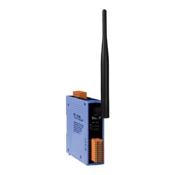
The WF-2000 DIO modules front panel contains the antenna, I/O connectors and LEDs. RP SMA Connector Signal strength System Status I/O Status I/O Connector Figure 2-1: Front Panel of the WF-2000 DIO modules WF-2000 Series DIO User’s Manual (RevB1.0, Oct./2016) ------------- 9... -
Page 10: Led Indicator
Table 2-2: Signal Strength LED Indicator Signal Strength LED Indicator LED Status Signal strength High Medium Bad or No Signal 2.1.2 I/O Connector 2.1.2.1 WF-2042 Figure 2-2: I/O Connector of WF-2042 WF-2000 Series DIO User’s Manual (RevB1.0, Oct./2016) ------------- 10... - Page 11 2.1.2.2 WF-2051 Figure 2-3: I/O Connector of WF-2051 2.1.2.3 WF-2055 Figure 2-4: I/O Connector of WF-2055 2.1.2.4 WF-2060 Figure 2-5: I/O Connector of WF-2060 WF-2000 Series DIO User’s Manual (RevB1.0, Oct./2016) ------------- 11...
-
Page 12: Top Panel
2000 firmware, the switch can be moved from the OP position to the FW position. Table 2-3: Power/Signal Connector Power/Signal connector Pin Assignment Description Frame Ground +10 ~ +30 VDC Power / RS-232 GND RS-232 RxD RS-232 TxD WF-2000 Series DIO User’s Manual (RevB1.0, Oct./2016) ------------- 12... -
Page 13: Dimensions
The diagrams below provide the dimensions of the WF-2000 to use in defining your enclosure specifications. All dimensions are in millimeters. Figure 2-7: Front / Left Side dimension of the WF-2000 Figure 2-8: Top / Bottom dimension of the WF-2000 WF-2000 Series DIO User’s Manual (RevB1.0, Oct./2016) ------------- 13... -
Page 14: Hardware Connection
The following figures describe the Power and the COM port to a serial device via serial network. Figure 2-9: Power and Serial port wire connection 2.4.2 I/O connection 2.4.2.1 WF-2042 Figure 2-10: DO wire connection of WF-2042 WF-2000 Series DIO User’s Manual (RevB1.0, Oct./2016) ------------- 14... - Page 15 2.4.2.2 WF-2051 Figure 2-11: DI Dry contact wire connection of WF-2051 Figure 2-12: DI Wet contact wire connection of WF-2051 WF-2000 Series DIO User’s Manual (RevB1.0, Oct./2016) ------------- 15...
- Page 16 2.4.2.3 WF-2055 Figure 2-13: DI Dry contact wire connection of WF-2055 Figure 2-14: DI Wet contact wire connection of WF-2055 WF-2000 Series DIO User’s Manual (RevB1.0, Oct./2016) ------------- 16...
- Page 17 Figure 2-15: DO wire connection of WF-2055 2.4.2.4 WF-2060 I/O Wire Connection Figure 2-16: DI Dry contact wire connection of WF-2060 WF-2000 Series DIO User’s Manual (RevB1.0, Oct./2016) ------------- 17...
- Page 18 Figure 2-17: DI Wet contact wire connection of WF-2060 Figure 2-18: DO wire connection of WF-2060 WF-2000 Series DIO User’s Manual (RevB1.0, Oct./2016) ------------- 18...
-
Page 19: Jumper Settings
Figure 2-19: Watchdog timer Jumper Position FW / OP Dip-switch On the top of the WF-2000 series module, there is a dip-switch used for firmware operation or firmware update of the module. The following steps show how to use this dip-switch. - Page 20 Figure 2-20: FW Position of Dip-Switch Figure 2-21: CA-0910 Cable Figure 2-22: Downloads cable connection WF-2000 Series DIO User’s Manual (RevB1.0, Oct./2016) ------------- 20...
- Page 21 The result will be shown in “Firmware Update” field. Figure 2-23: WF-2000 firmware update process The WF-2000 firmware can be downloaded from ftp://ftp.icpdas.com/pub/cd/usbcd/napdos/wifi/io/wf-20xx/firmware The Firmware_Update_Tool program can be downloaded from ftp://ftp.icpdas.com/pub/cd/usbcd/napdos/wifi/io/wf- 20xx/software/tool/ WF-2000 Series DIO User’s Manual (RevB1.0, Oct./2016) ------------- 21...
-
Page 22: Firmware Operation Mode
In the operation mode, users need to set the dip-switch to the “OP” position as Figure 2-24 and reset the power, and the WF-2000 can run in the operation mode. In this mode, user can use the WF-2000 series with a computer or with another WF-2000 series module for wireless connection. -
Page 23: Software
"Device List", and then you will see the I/O page come out. In the I/O page, it is used to access I/O data and configure parameters. WF-2000 Series DIO User’s Manual (RevB1.0, Oct./2016) ------------- 23... -
Page 24: Main Screen
This function can enter the basic Pair Connection configuration interface, as shown in Figure 3-5. [3] Search List Search list provides each item that scans from UDP and display the related information about the device, includes host name, alias WF-2000 Series DIO User’s Manual (RevB1.0, Oct./2016) ------------- 24... -
Page 25: Configuration Screen
DHCP server when the DHCP function is enabled. (Limited AP mode don't support DHCP configuration) IP Address WF-2000 IP setting (Default:192.168.255.1) Subnet Mask WF-2000 Net Mask setting (Default: 255.255.0.0) WF-2000 Series DIO User’s Manual (RevB1.0, Oct./2016) ------------- 25... - Page 26 Auto search the broadcast SSID in the air, and list SSID names in the drop-down menu. (It must establish a Wi-Fi connection first, and communicate with Wi-Fi Interface) Figure 3-3: Auto search SSID list WF-2000 Series DIO User’s Manual (RevB1.0, Oct./2016) ------------- 26...
- Page 27 Characters of key should be in range of: [0 ~ 9] or [A ~ F] or [a ~ f]. [3] General F/W Version Display the firmware version of the WF-2000 Date created Display the date created of the WF-2000 WF-2000 Series DIO User’s Manual (RevB1.0, Oct./2016) ------------- 27...
-
Page 28: Data Acquisition Screen
Parameter Transmission Interface The parameter transmission interface, that provides Wi-Fi and RS-232 interface for connection. Write Parameter It allows users to upload the parameters to WF-2000 series Read Parameter It allows users to download the parameters form WF-2000 series. 3.1.3 Data Acquisition Screen In the I/O page of the DI and DO, the real-time value and module configuration can be read or written in this page. - Page 29 Active Time (ms): This function is active when the communication timeout reach this setting. Polling Interval This value is the period to poll data to the WF-2000 I/O module. Note: The valid value is 100 ~ 5000 ms. WF-2000 Series DIO User’s Manual (RevB1.0, Oct./2016) ------------- 29...
- Page 30 Figure 3-5: Pair connection configuration screen Enable I/O Pair Connection: Enable/Disable I/O pair connection. Remote Net ID: Modbus Net ID of remote device. Remote IP Address: IP address of remote input device. WF-2000 Series DIO User’s Manual (RevB1.0, Oct./2016) ------------- 30...
- Page 31 Communication Timeout (sec): The period of which the WF-2000 series is waiting for a response from the remote DI device. Local DO Base Address: DO base address of local DO register will be mapped to remote DI device. Remote DI Base Address: DI base address of Remote DI device that will be mapped to local DO register.
-
Page 32: Application Notes
Step 1: Checking the WF-2000 series firmware operation mode It needs to set the DIP switch to the "OP" position (operating mode), as resetting the power, WF-2000 series will be in the operation mode. Step 2: Serial port connection WF-2000 series supports RS-232 serial communication. The circuit configuration is as shown in Figure 2-9. -
Page 33: Wf-2000 Series Configuration
01、Net ID : The Unit Identifier in Modbus TCP/IP application data unit. This case is set as "1" in Figure 4-3. 02、IP Address : Set the local WF-2000 series' IP. Here set to "192.168.255.1". 03、Subnet Mask : Net Mask settings. Here set to "255.255.0.0". -
Page 34: Pc Connection Configuration
Open Network connections and entry the properties setting of wireless network connections. Figure 4-4: Properties setting of wireless network connections b. Select the Internet Protocol (TCP/IP) and press the "Properties" button. Figure 4-5: Properties setting of Internet Protocol (TCP/IP) WF-2000 Series DIO User’s Manual (RevB1.0, Oct./2016) ------------- 34... - Page 35 View available wireless networks and you can see the "WF- 20xx" wireless network in the list. b. Select the "WF-20xx" and press the "Connect" button. Figure 4-7: Wireless network connection WF-2000 Series DIO User’s Manual (RevB1.0, Oct./2016) ------------- 35...
-
Page 36: Access I/O Data
Open WF I/O utility and click the "Search" button, choose the network interface that connect with the WF-2000 device, search list will provide each item that scan from UDP Port. Figure 4-10 Choose Network Interface WF-2000 Series DIO User’s Manual (RevB1.0, Oct./2016) ------------- 36... - Page 37 If the network settings are correct, this will immediately establish a connection. c. Use the function code "0x02", and set the Reference Number as "0x00", Bit Count as "0x10" to get the 16 CHs DI value. WF-2000 Series DIO User’s Manual (RevB1.0, Oct./2016) ------------- 37...
- Page 38 Use the function code "0x04", and set the Reference Number as "0x32", Word Count as "0x10" to get the 8 CHs Counter value (4 bytes each counter). Figure 4-14: Counter reading screen WF-2000 Series DIO User’s Manual (RevB1.0, Oct./2016) ------------- 38...
-
Page 39: Modbus Applications
The Modbus protocol defines a simple protocol data unit independent of the underlying communication layers. The mapping of Modbus protocol on network can introduce some additional fields on the application data unit. WF-2000 Series DIO User’s Manual (RevB1.0, Oct./2016) ------------- 39... -
Page 40: Mbap
Modbus Client to a Server device the function code field tells the Server what kind of action to perform. The Modbus/TCP feature of WF-2000 series module supports 7 function codes, which allows the reading and writing of data contents of WF-2000 Series DIO User’s Manual (RevB1.0, Oct./2016) ------------- 40... -
Page 41: Data
Table 5-2: Supports Function Codes of WF-2000 series Function Code Descriptions 01 (0x01) Read Coil Status 02 (0x02) Read Input Status 03 (0x03) Read Holding Registers 04 (0x04) Read Input Registers 05 (0x05) Force Single Coil 15 (0x0F) Force Multiple Coils... -
Page 42: Data Encoding
01 and 02. Therefore, a single register contains 16 bits of binary data, each having a specific meaning. Table 5-3: A single register contains 16 bits of binary data Value 0xAA55 0xAA 0x55 (1010101001010101) (10101010) (01010101) WF-2000 Series DIO User’s Manual (RevB1.0, Oct./2016) ------------- 42... -
Page 43: Address Mapping
Access Type 00001 1~16 Digital Output 0=OFF, 1=ON Table 5-6: (4xxxx) AO address Begin Address Points Descriptions Range Access Type 1= Reset System 247= Restore to 40248 Reset System Factory Default Settings WF-2000 Series DIO User’s Manual (RevB1.0, Oct./2016) ------------- 43... -
Page 44: Wf-2051 I/O Address Mapping
30071 0~4294967295 (2 points/ Each Counter Channel) Table 5-10: (4xxxx) AO address Begin Address Points Descriptions Range Access Type 1= Reset System 247= Restore to 40248 Reset System Factory Default Settings WF-2000 Series DIO User’s Manual (RevB1.0, Oct./2016) ------------- 44... -
Page 45: Wf-2055 I/O Address Mapping
30071 0~4294967295 (2 points/ Each Counter Channel) Table 5-14: (4xxxx) AO address Begin Address Points Descriptions Range Access Type 1= Reset System 247= Restore to 40248 Reset System Factory Default Settings WF-2000 Series DIO User’s Manual (RevB1.0, Oct./2016) ------------- 45... -
Page 46: Wf-2060 I/O Address Mapping
30071 0~4294967295 (2 points/ Each Counter Channel) Table 5-18: (4xxxx) AO address Begin Address Points Descriptions Range Access Type 1= Reset System 247= Restore to 40248 Reset System Factory Default Settings WF-2000 Series DIO User’s Manual (RevB1.0, Oct./2016) ------------- 46... -
Page 47: Troubleshooting
3. When the correct implementation of the above steps, the Signal Strength LEDs and PWR/Wi-Fi Step4 LEDS of the WF-2000 series should be turn on, and that should be turn off after 500 ms later. 4. Reset the power the WF-2000 series would back to factory defaults. - Page 48 Microsoft .NET Framework 4 (Standalone Installer) http://www.microsoft.com/en- us/download/details.aspx?id=17718 Figure 6-1: .NET Framework Initialization Error Technical Support If you have problems about using the WF-2000 series I/O module, please contact ICP DAS Product Support. Email: service@icpdas.com WF-2000 Series DIO User’s Manual (RevB1.0, Oct./2016) ------------- 48...
Need help?
Do you have a question about the WF-2000 Series and is the answer not in the manual?
Questions and answers