Table of Contents
Advertisement
Quick Links
Advertisement
Table of Contents

Related Manuals for Bdcom S5864


Summary of Contents for Bdcom S5864
- Page 1 S5864 Hardware Installation Manual...
-
Page 2: Table Of Contents
Table of Contents Table of Contents Chapter 1 S5864 Introduction........................1 1.1 Appearance Description for Standard Configuration..............1 1.2 S5864 Systematic Characteristic Parameters................2 1.3 ROHS Description..........................4 Chapter 2 Installation Preparation........................ 5 2.1 Caution of Usage..........................5 2.2 Safety Advice.............................5 2.2.1 Safety Principles........................5... - Page 3 3.3.3 Connecting Ethernet Management Ports................ 12 3.3.4 Connecting 40GE Ethernet QSFP+ Ports...............14 Table of Contents 1.3.1 USB Interface........................15 3.4 Checking After Installation......................15 Chapter 4 Maintaining Switch........................17 4.1 Opening the Machine Box......................17 4.2 Closing Machine Box........................18 Chapter 5 Hardware Fault Analysis......................19 5.1 Fault Separation..........................
- Page 4 5.2 Indicator Description........................19...
-
Page 5: Chapter 1 S5864 Introduction
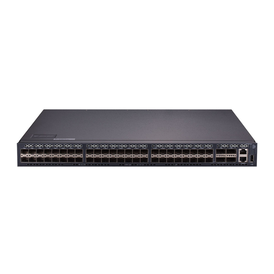
The section describes the characteristics and parameters of S5864 and gives an overview of S5864. Appearance Description for Standard Configuration The built-in ports of S5864 are: 48 10GE SFP+ ports, 4 40GE QSFP+ ports, 1 console See table 1-1. port, 1 gigabit management port and 1 USB interface. -
Page 6: S5864 Systematic Characteristic Parameters
S5864 Hardware Installation Manual LED indicators System/power supply indicators Figure 1- 2 Back template of the S5864 switch Table 1-3 Parts at the back template of the S5864 switch Abbrev. Name Description 1,3,5,7 Grounding column The grounding must be fine. - Page 7 S5864 Hardware Installation Manual 48 SFP+ 10GE optical ports 4 10GE QSFP+ ports 1 Console port Standard configuration 1 USB interface 1 gigabit management interface Dimensions mm 442.5×404×44 (W×D×H) Operating 0℃ ~40℃ ; 10%~85% non-condensing temperature/ humidity Storage temperature/ -40℃ ~80℃ ; 5%~95% non-condensing humidity Input voltage: AC100~240V,...
-
Page 8: Rohs Description
Similar to other electronic products, the semiconductor chip easily gets damaged if you power on or off abruptly and frequently. To restart up the switch of S5864, you have to open the power on-off after the power is cut down for three to five seconds. -
Page 9: Safety Advice
S5864 Hardware Installation Manual Use correct outside ports to connect the switch of S5864. Do not put the Ethernet plug into the console port (RJ45 8-line socket). Similarly, do not put the console cable into the console port (RJ45 8-line socket). -
Page 10: Electrostatic Discharge Damage Prevention
S5864 Hardware Installation Manual Pull out the AC power socket and close the direct-current power before operating on the machine box or working beside the power source. When the power is on, do not touch the power. ... -
Page 11: Environment
S5864 Hardware Installation Manual 2.3.1 Environment The switch can be installed on the desk or the cabinet. The location of the machine box, cabinet planning and indoor cabling are very important for normal system’s function. Short distance between devices, bad ventilation and untouchable control plate will cause maintenance problems, systematic faulty and breakdown. -
Page 12: Installation Tools And Device
2.4 Installation Tools and Device The tools and devices to install the S5864 switch are not provided by the S5864 switch. You yourself need to prepare them. The following are the tools and devices needed for the typical installation of the S5864 switch: ... -
Page 13: Installing The Machine Box Of The Switch
Installing the machine box on the cabinet 3.2.1 Installing the Machine Box on the Desk The S5864 switch can be directly put on the smooth and safe desk. Note: Do not put things weighing 4.5 kg or over 4.5 kg on the top of the switch. -
Page 14: Connecting The Port
STAR-510G+ or PC through a console cable, you can configure and monitor the switch of S5864 by running a terminal emulation software, such as super Windows terminal. The cable is provided according to the host. -
Page 15: Connecting 10Ge Ethernet Sfp+ Ports
One end is RJ45 8-core plug, and the other end of the console cable is DB9. The RJ45 plug is put into the socket of the console port on the S5864 switch. The inner line connection in the cable is shown in figure 3-1. The console cable is numbered as RLC0301. -
Page 16: Connecting Ethernet Management Ports
S5864 Hardware Installation Manual Figure 3-6 Connecting the 10GE SFP+ port and other Ethernet terminals Caution: The switch shown in figure 3-5 does not represent the material S5864. 3.3.3 Connecting Ethernet Management Ports S5864 provides 1 10/100/1000Base-T port. Each port has its corresponding MNG indicator. -
Page 17: Connecting 40Ge Ethernet Qsfp+ Ports
Sending/receiving the paraphase of the data 3 TP3- 3.3.4 Connecting 40GE Ethernet QSFP+ Ports S5864 provides with 4 40GE QSFP+ ports. Each port has its corresponding indicator: 1~4. The four ports can be configured into 2 modes: Set the rate of the port to 40Gbps... - Page 18 S5864 Hardware Installation Manual Figure 3-9 Connecting the 40GE QSF+ port and other Ethernet terminals Set the ports to 4 10GE ports You can connect the QSFP+ optical module to the optical port and then you can connect other Ethernet terminal devices with 10GE optical ports through the MPO-4*LC optical cable.
-
Page 19: Usb Interface
S5864 Hardware Installation Manual Figure 3-10 Connecting the 40GE QSF+ port and other Ethernet terminals Caution: The switch shown in figure 3-10 does not represent the material S5864. 1.3.1 USB Interface S5864 provides with 1 USB2.0 interface. Figure 3-11 Connecting USB2.0 interface 3.4 Checking After Installation... - Page 20 S5864 Hardware Installation Manual If the switch is installed on the cabinet, check whether the installation point between the cabinet and the switch is strong. If the switch is installed on the desk, check whether there is enough space for the switch to discharge its heat and whether the desk is stable.
-
Page 21: Chapter 4 Maintaining Switch
Open the cover by holding two sides of the cover towards the direction of the arrow key shown in the following figure: Caution: The switch shown in the above figure does not represent the material S5864. When the cover is opened, put it aside. The mainboard of the system appears. -
Page 22: Closing Machine Box
S5864 Hardware Installation Manual After taking off the cover, put it horizontally and avoid it to be crushed or collided. Otherwise, the machine box is hard to install. 4.2 Closing Machine Box The section mainly describes how to put the cover and close the machine box. Do as follows: Put them well according to their locations and joint them together along their sides. -
Page 23: Faults Relative With Port, Cable And Connection
9600 bps, eight data bits, no sum check bit, one stop bit and no traffic control. 5.2 Indicator Description The LED indicator shows that the switch is running. The following table shows the indicators of the S5864 switch and their description: Abbrev. Name Description... - Page 24 S5864 Hardware Installation Manual 1. work in the mode of 40GE If the indicator is always on, the system is normally linked. If the indicator is off, the port is not linked. indicator flickers, there data transmission. QSFP+ port indicator 2 ....
- Page 25 S5864 Hardware Installation Manual Figure 5-2 40GE BREAKOUT indicator Figure 5-3 QSFP+ port indicator Copyright Claims Without the written approval of the company , any person or group cannot transcribe, copy or change partial or all contents of this manual, and must not broadcast it in any manner.
Need help?
Do you have a question about the S5864 and is the answer not in the manual?
Questions and answers