Otto Bock Dino 3 Instructions For Use Manual
Hide thumbs
Also See for Dino 3:
- Instructions for use manual (152 pages) ,
- Service manual (34 pages) ,
- User manual (20 pages)

Related Manuals for Otto Bock Dino 3


Summary of Contents for Otto Bock Dino 3
- Page 1 Dino 3 Instructions for use (user) ..................
- Page 2 Dino 3...
-
Page 3: Table Of Contents
Approach in case of stiffness ........................ Wheel locks ............................7.5.1 Using the drum brake as a wheel lock ....................7.5.2 Using the knee lever wheel lock for parking (option) ................7.5.3 Readjusting the knee lever wheel lock ....................Dino 3... - Page 4 Special features for wheels with PU tyres ....................Disposal ................................Disposal information ..........................Legal information .............................. 10.1 Liability .............................. 10.2 Warranty ............................10.3 Service life ............................Technical data ..............................Appendices ................................ 12.1 Threshold values for wheelchairs transportable by train ................12.2 Required tools ............................ Dino 3...
-
Page 5: Foreword
The manufacturer reserves the right to make technical changes to the model described in these instructions for use. 2 Product description 2.1 Function The product is intended exclusively for holding modular orthopaedic seating solutions to transport one person on the seat. The product can be used on solid ground both indoors and outdoors. Dino 3... -
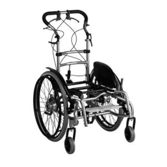
Page 6: Product Overview
Clamping lever (push bar height adjustment) Knee lever wheel lock (optional) Clamping lever (push bar angle adjustment, optional) Leg support (optional) Release lever/Bowden cable for seat tilt Main frame Brake lever/Bowden cable for drum brake Caster fork Push bar Caster wheel Dino 3... -
Page 7: Transport Chair
The product is intended for everyday indoor and outdoor use, by an attendant, of people with temporary or perman ent limitations of the ability to walk, inability to walk or difficulty standing up. Special feature for versions with 22"/24" drive wheels: The product can be operated independently by the user. Dino 3... -
Page 8: Indications
► Users with the necessary physical and psychological preconditions can be supplied with such versions/set tings. If the physical/psychological preconditions change, the product may no longer be used with these set tings. Inform the responsible qualified personnel immediately in this case. Dino 3... - Page 9 Tipping over, rolling over of the user due to failure to observe specifications ► Using the rehab buggy beyond normal conditions can be dangerous. ► Please note that this product is not suitable for jogging, running, skating, etc. ► Do not exceed the max. load capacity (see Page 43). Dino 3...
- Page 10 User may fall or tip over due to driving error ► Only cross railway systems and railway tracks in the designated areas. ► Negotiate level crossings so the caster wheels of the product cannot get caught in the gap between the rail and the road surface. Dino 3...
- Page 11 Activate the anti-tipper again afterwards. ► The anti-tipper has to engage audibly prior to use. Verify a firm fit. ► If you believe the anti-tipper needs to be adjusted, please contact the qualified personnel that adapted the product. Dino 3...
- Page 12 Use of the product during diagnostic examinations and therapeutic treatment Impairment of the examination results or the effectiveness of treatment due to interactions of the product with devices that are used ► Make sure that examinations and treatments are carried out exclusively under the prescribed conditions. Dino 3...
-
Page 13: Side Effects
The serial number required for enquiries and orders can be found on the nameplate. For explanations of the nameplate, see the section "Nameplate" (see Page 14). 4.5 Nameplate and warning labels 4.5.1 Signage on the product The warning signs and nameplates are attached to the product at the following mounting points: Dino 3... -
Page 14: Nameplate
UDI-DI to GS1 standard; UDI = Unique Device Identifier, DI = Device Identifier 4.5.3 Warning labels Label Meaning (Only in case of installation of ISO sets according to ISO 7176-19) Fixation point/eyebolt to attach the product in vehicles for trans porting persons with reduced mobility Dino 3... -
Page 15: Delivery
The qualified personnel must complete these tasks according to the manufacturer’s specifications. ► Have yourself instructed in the safe adaptation of the seating solution from another manufacturer. ► Ottobock assumes no liability in case of problems with seating solutions from other manufacturers. Dino 3... -
Page 16: Use
The recommended overall width for manual wheelchairs or comparable products in an operational state is 700 mm. This specification should ensure unhindered use of escape routes, for example. Please note that the product dimensions can exceed the recommended value in versions with very large seat widths (for more information see see Page 43 ff.). Dino 3... -
Page 17: Getting In And Transferring
→ If the user does not meet the physical prerequisites due to their disability, support should be provided by an attendant. → After gripping frame components or the arm support, the user may be able to pull him or herself onto the seat independently or support the transfer. Dino 3... -
Page 18: Seat (Option)
All seat settings have already been adapted to the needs of the user by the qualified personnel when the product was delivered. When the product is handed over to the user, the qualified personnel instructs the user in the use of the chosen seating solution. Dino 3... -
Page 19: Using Interface Adapters
→ The locking mechanism is released. 3) Bring the seat to the desired angle by moving the push handles/push bar (see fig. 11). 4) Let go of the release lever. → The seat is secured at the desired angle. Dino 3... -
Page 20: Adjusting The Back Support Angle
5) Engage the threaded bar in the fixture on the rear cross tube (see fig. 13, item 2). → The back support frame is secured at the desired angle. 7.3.4.2 Adjustment with release lever (option) 1) Hold the push handles/push bar firmly. Dino 3... -
Page 21: Removing/Attaching The Seating Shell/Seating Solution
3) Press the front edge of the seat onto the mobility base until the retaining claw audibly snaps onto the front tube of the seat adapter. 4) Check that the seat and the mobility base are securely connected. You can do this, for example, by pulling back the back support. Dino 3... -
Page 22: Seating Solutions With Trapezoid Adapter
1) Loosen the clamping screw on the back guide (see fig. 19, item 2). 2) Twist the back guide onto the cross tube. 3) Firmly tighten the clamping screw on the back guide (see fig. 19, item 2). Dino 3... -
Page 23: Wheels
1) Grip the area between the spokes near the hub with your fingers (see fig. 20). 2) Use your thumb to press in the push-button on the quick-release axle. 3) Remove/attach the drive wheel. The quick-release axle must not be removable after releasing the push-button. Dino 3... -
Page 24: Spoke Protectors (Option)
(see fig. 21, item 2). 3) Lubricate the upper and lower ends of the threaded axle with a few drops of thin, resin-free oil (sewing machine oil). 4) Install the protective cap on the caster head. Dino 3... -
Page 25: Wheel Locks
► Verify the functionality of the wheel lock prior to every use. ► Always carry out adjustments to the wheel locks on both sides. ► Maintain sufficient air pressure in pneumatic tyres. For the correct air pressure, see the section "Technical data". Dino 3... - Page 26 ► Pull the handle of the knee lever wheel lock to the back (see fig. 25). → The wheel lock bolt releases the wheel. Plug-on wheel lock lever extension The wheel lock lever extension makes it easier for users with limited hand function to use the knee lever wheel lock (see fig. 26, item 1). Dino 3...
-
Page 27: Readjusting The Knee Lever Wheel Lock
The angle of the footplate has been set by the qualified personnel so that it supports the ankles in a comfortable position. Subsequent adjustments may be made only by qualified personnel. Segmented leg supports with heel bands can be optionally fitted to provide the user's feet with additional support (see fig. 29). Dino 3... -
Page 28: Removing/Installing The Leg Supports
3) Fold down the foot plates. 4) Optional: Engage the calf strap on the holder (see fig. 35, item 1) and adjust the length of the calf band. To do so, open the hook-and-loop closure, make the adjustment and fasten the closure. Dino 3... -
Page 29: Folding Up The Foot Plates
7.6.3 Adjusting the foot plate angle Subsequent adjustments to the footplates may be made only by qualified personnel. 7.6.4 Adjusting the knee angle of the leg support The knee angle of the following leg supports can be adjusted as needed. Dino 3... -
Page 30: Removing And Fastening The Calf Strap
2) Adjust the height of the push handles. INFORMATION: The maximum adjustment range is 150 mm. 3) Firmly tighten the clamping levers on the right/left sides of the back support tubes (see fig. 41, item 1). INFORMATION: Adjust both push handles to the same height. Dino 3... -
Page 31: Adjusting The Push Bar With Ratchet Joints (Option)
Side panel with clothing guard for 22" and 24" wheels The arm support provides support for the forearm. The clothing guard protects against dirt. The side panels are adapted as needed by qualified personnel. Subsequent adjustments may be made only by qualified personnel. Dino 3... -
Page 32: Anti-Tipper (Option)
The tip-assist (see fig. 44) makes it easier for an attendant to tip up the mobility base for seating shells, e.g. to cross a step/curb: 1) At an obstacle, place one foot on the tip-assist and push down. 2) Simultaneously pushing down on the push handles/push bar allows the mobility base for seating shells to be tipped up easily. Dino 3... -
Page 33: Tray (Option)
The tray serves as a supporting surface during meals, when working or when playing. Its transparency permits examination of the legs and correction of the sitting posture. Mounting the tray ► Slide the tray (see fig. 45) onto the arm supports. INFORMATION: Leave enough space for the person using the mobility base for seating shells. Dino 3... -
Page 34: Adapter For Stairclimber (Option)
6) Optional: Set the height of the push handles/push bar as low as possible (see Page 30). If push handles are installed: Turn the push handles to the inside. For push bar with ratchet joints: Fold the push bar forward. 7) For drive wheels with quick-release axle: Remove the drive wheels (see Page 23). Dino 3... -
Page 35: Use In Vehicles For Transporting Persons With Reduced Mobility
The transport weight of the person being transported in a vehicle for transporting persons with reduced mobility is limited to the maximum total load capacity (weight with seating shell). Further information: see Page 43 Dino 3... -
Page 36: Required Accessories
(see fig. 49 item 2). • The shoulder belt must always be routed over the user’s shoulder (see fig. 49, item 1). • The belt strap must not be twisted on the user’s body. Dino 3... - Page 37 6) Secure the shoulder harness on the mounting point/pin provided on the lap belt (not illustrated). → The restraint lap belt is pulled through and fastened. → The belt runs between the upholstery and frame on each side. Dino 3...
-
Page 38: Restrictions For Use
Do not use any aggressive cleaners, solvents or hard brushes etc. • Do not spray the product with a pressure washer. 7.16.2 Disinfection 1) Thoroughly clean the handles before disinfecting. 2) Wipe all parts of the product with a disinfectant. Dino 3... -
Page 39: Maintenance And Repair
Check the swivel axis for ease of operation Check that screw connections for angle adjust ment are tight Check that the seat tilt locks securely Back support Check attachment for firm fit Check that release bolts engage fully Dino 3... -
Page 40: Maintenance Tasks
WARNING Prohibited repairs Severe user injuries, damage to the product due to adjustment and installation errors ► Only carry out the repairs described in this section. All other repairs may only be carried out by the qualified personnel. Dino 3... -
Page 41: Inner Tube, Rim Tape And Tyre Replacement
4) Insert the tube into the tyre. 5) Mount the other side of the tyre on the rim, starting from the position across the valve. Ensure that the tube is not pinched between the tyre and rim during this process. Dino 3... -
Page 42: Special Features For Wheels With Pu Tyres
10.3 Service life Expected lifetime: 4 years The design, manufacturing and requirements for the intended use of the product are based on the expected life time. These also include the requirements for maintenance, ensuring effectiveness and the safety of the product. Dino 3... -
Page 43: Technical Data
12.5 PU/pneumatic Drive wheel (self-propelled) With maximum installation of accessories Depending on seat positioning and anti-tipper setting In reference to seating shell mobility base without seating unit Depending on leg support and seating unit For 22"/24" drive wheels Dino 3... -
Page 44: Appendices
Feature Threshold value (according to Directive (EU) No. 1300/2014) Length [mm] 1200 (plus 50 mm for the feet) Width [mm] 700 (plus 50 mm on each side for the hands when mov ing) Dino 3... -
Page 45: Required Tools
6 (dynamic stability in all directions) remain stable [°] 9 (static stability in all directions, also when wheel lock engaged) 12.2 Required tools The following tools are required for adjustments and maintenance work: • Allen key 4 – 6 mm • Tyre lever • Tyre pump Dino 3... - Page 46 Dino 3...
- Page 47 · www.ottobock.de 143441 Moscow Region/Krasnogorskiy Rayon info@ottobock.com.co · www.ottobock.com.co Russian Federation Otto Bock Healthcare Products GmbH Otto Bock de Mexico S.A. de C.V. T +7 495 564 8360 · F +7 495 564 8363 Brehmstraße 16 · 1110 Wien · Austria Prolongación Calle 18 No. 178-A info@ottobock.ru · www.ottobock.ru F +43 1 5267985...
- Page 48 Ihr Fachhändler | Your specialist dealer Otto Bock Mobility Solutions GmbH Lindenstraße 13 · 07426 Königsee/Germany www.ottobock.com...
Need help?
Do you have a question about the Dino 3 and is the answer not in the manual?
Questions and answers