Table of Contents
Advertisement
Quick Links
Advertisement
Table of Contents

Related Manuals for KSB SRA


Summary of Contents for KSB SRA
- Page 1 Pump Station Installation/Operating Manual...
- Page 2 Legal information/Copyright Installation/Operating Manual SRA Original operating manual All rights reserved. The contents provided herein must neither be distributed, copied, reproduced, edited or processed for any other purpose, nor otherwise transmitted, published or made available to a third party without the manufacturer's express written consent.
-
Page 3: Table Of Contents
Contents Contents Glossary .............................. 5 General.............................. 6 Principles ................................ 6 Target group.............................. 6 Other applicable documents.......................... 6 Symbols ................................ 6 Key to safety symbols/markings........................ 7 Safety .............................. 8 General................................ 8 Intended use .............................. 8 2.2.1 Prevention of foreseeable misuse....................... 8 Personnel qualification and training....................... 9 Consequences and risks caused by non-compliance with this manual ............ 9 Safety awareness .............................. 9 Safety instructions for the operator/user...................... 9 Safety information for maintenance, inspection and installation .............. 10... - Page 4 Contents 6.2.2 Fluid handled ............................. 41 Shutdown................................ 42 Returning to service ............................ 42 Servicing/Maintenance ........................ 43 General instructions ............................ 43 Inspection contract ............................ 43 Servicing/Inspection............................ 44 7.3.1 Maintenance schedule........................ 44 7.3.2 Maintenance checklist ........................ 44 Entering the collecting tank .......................... 45 Trouble-shooting.......................... 47 Related Documents .......................... 49 General drawings with list of components.................... 49 9.1.1 Collecting tank ........................... 49 9.1.2...
-
Page 5: Glossary
Glossary Glossary Certificate of decontamination A certificate of decontamination is enclosed by the customer when returning the product to the manufacturer to certify that the product has been properly drained to eliminate any environmental and health hazards arising from components in contact with the fluid handled. -
Page 6: General
1 General 1 General 1.1 Principles This operating manual is valid for the type series and variants indicated on the front cover. The operating manual describes the proper and safe use of this equipment in all phases of operation. The name plate indicates the type series/size and main operating data. The works number/serial number uniquely describes the system and is used as identification in all further business processes. -
Page 7: Key To Safety Symbols/Markings
1 General 1.5 Key to safety symbols/markings Table 3: Definition of safety symbols/markings Symbol Description DANGER DANGER This signal word indicates a high-risk hazard which, if not avoided, will result in death or serious injury. WARNING WARNING This signal word indicates a medium-risk hazard which, if not avoided, could result in death or serious injury. -
Page 8: Safety
2 Safety 2 Safety All the information contained in this section refers to hazardous situations. DANGER In addition to the present general safety information the action-related safety information given in the other sections must be observed. 2.1 General ▪ This operating manual contains general installation, operating and maintenance instructions that must be observed to ensure safe operation of the system and prevent personal injury and damage to property. -
Page 9: Personnel Qualification And Training
2 Safety 2.3 Personnel qualification and training ▪ All personnel involved must be fully qualified to install, operate, maintain and inspect the product this manual refers to. ▪ The responsibilities, competence and supervision of all personnel involved in transport, installation, operation, maintenance and inspection must be clearly defined by the operator. -
Page 10: Safety Information For Maintenance, Inspection And Installation
2 Safety 2.7 Safety information for maintenance, inspection and installation ▪ Modifications or alterations of the system require the manufacturer's prior consent. ▪ Use only original spare parts or parts authorised by the manufacturer. The use of other parts can invalidate any liability of the manufacturer for resulting damage. ▪... -
Page 11: Unauthorised Modes Of Operation
2 Safety When entering the collecting tank, be aware of the following dangers: ▪ Biological processes, e.g. fermentation, digestion ▪ Formation of potentially explosive atmospheres ▪ Lack of oxygen ▪ Hazardous substances which can be absorbed via the skin or inhaled ▪... -
Page 12: Transport/Storage/Disposal
3 Transport/Storage/Disposal 3 Transport/Storage/Disposal 3.1 Checking the condition upon delivery 1. On transfer of goods, check each packaging unit for damage. 2. In the event of in-transit damage, assess the exact damage, document it and notify or the supplying dealer and the insurer about the damage in writing immediately. -
Page 13: Storage / Preservation
3 Transport/Storage/Disposal Fig. 2: Securing the collecting tank against tipping over / rolling off Valve pit Fig. 3: Transporting the valve pit (example) ü Transport equipment / lifting equipment suitable for the corresponding weight (see data sheet) has been selected and is on hand. 1. -
Page 14: Return To Supplier
NOTE If required, a blank certificate of decontamination can be downloaded from the following web site: www.ksb.com/certificate_of_decontamination 1. Drain the collecting tank properly. 2. Flush and clean the collecting tank and and its internal parts, particularly if they have been used for handling noxious, explosive, hot or other hazardous fluids. -
Page 15: Description
See name plate and data sheet of the collecting tank See name plate and data sheet of the valve pit Table 5: Designation key Position Code Description Type series SRA Pump Station Size / diameter of the collecting tank 1000 1400 1800 9-10 Height of the collecting tank 2,5 m... - Page 16 4 Description Position Code Description 19-20 Piping made of PVC and valves made of grey cast iron EN-GJL-250 with epoxy resin paint RAL 5002 Piping made of stainless steel 316L (1.4404) and valves made of grey cast iron EN-GJL-250 with epoxy resin paint RAL 5002 22-23 Size / diameter of the valve pit 1000 mm...
-
Page 17: Name Plate
SRA COLLECTING TANK SRA1000 × 22 - PCR050CPG 9974XXXXXX / 000100 09/12/2020 KSB SAS 10 rue de la gare, 76250 Déville-lès-Rouen FRANCE Fig. 4: Name plate of the collecting tank (example) 1 Type series 3 Production number 2 Type series code, size and version 4 Year of construction (ð Section 4.3, Page 15) -
Page 18: Design Details
4 Description 4.5 Design details Design ▪ Ready-to-connect dual-pump station ▪ Amaclean self-cleaning tank insert made of glass fibre reinforced polyester with special gel coating ▪ Collecting tank made of glass fibre reinforced polyester ▪ Tank cover, single-piece or two-piece ▪... -
Page 19: Configuration And Function
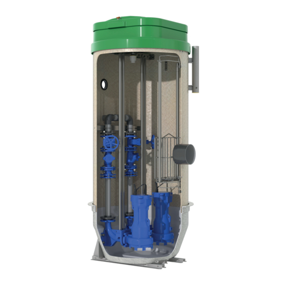
4 Description 4.6 Configuration and function Collecting tank Fig. 6: Illustration of the collecting tank (example) 1 Tank cover 11 Discharge connection 2 Manhole cover ring 12 Piping with valves 3 Socket for lifting equipment 13 Sensor system 4 Overflow connection 14 Flanged bend 5 Screen basket 15 Base reinforcement... -
Page 20: Scope Of Supply
4 Description version. For installation under traffic areas the collecting tank can be fitted with a manhole cover ring (2). Function The fluid handled enters the collecting tank via the inlet connection (6) and collects in the tank. A screen basket (5) filters coarse solids out of the fluid handled. When the set fill level is reached, the sensor system (13) sends a signal to the control unit (19), and the submersible motor pumps (7) are started up. -
Page 21: Installation At Site
5 Installation at Site 5 Installation at Site 5.1 General NOTE Do not operate pump stations near living quarters and sleeping quarters. 5.2 Preparing the construction pit CAUTION Clogging of the piping / formation of air pockets Damage to the pump station! ▷... - Page 22 5 Installation at Site Installation at high groundwater level ü Keep the construction pit dry for the entire construction time. The system for lowering the groundwater level (if available) has been started up. 1. Excavate the construction pit to DIN 4124 / DIN 18300 and VOB. Observe the slopes of the respective soil class (slope angle, planking/strutting requirements, etc).
-
Page 23: Installing The Collecting Tank
5 Installation at Site 5.3 Installing the collecting tank NOTE The collecting tank is water-tight up to its upper edge. Fig. 12: Positioning the collecting tank in the construction pit ü The construction pit has been properly prepared. (ð Section 5.2, Page 21) ü Transport equipment / lifting equipment suitable for the corresponding weight (see data sheet) has been selected and is available. -
Page 24: Installing The Valve Pit (Optional)
5 Installation at Site 5.4 Installing the valve pit (optional) CAUTION Clogging of the piping / formation of air pockets Damage to the pump station! ▷ The height of the discharge connection of the valve pit has to be equal to or above the height of the discharge nozzle of the collecting tank. -
Page 25: Connecting The Piping
5 Installation at Site 5.5 Connecting the piping WARNING Excess pressure in the discharge line Risk of injury by fluid spurting out, if pipeline not sealed properly. ▷ Wear safety clothing and a protective mask. CAUTION Stresses and strains at the piping Impermissible loads acting on the collecting tank! ▷... - Page 26 5 Installation at Site 5. Fit the cable conduit at the cable entry (3) of the collecting tank. 6. If applicable, connect the overflow line to the overflow connection (1) with a flexible low-pressure pipe coupling as per the manufacturer’s product literature and the local regulations.
- Page 27 5 Installation at Site Drainage with valves in a valve pit Fig. 17: Connections of a collecting tank with valves in the valve pit 1 Overflow connection (optional) 6 Drain line connection 2 Inlet line connection 7 Leakage return connection 3 Cable entry 8 Inlet line connection 4 Leakage return connection 9 Drain line connection...
- Page 28 5 Installation at Site 8. Fasten the hose to the leakage return connection (7) of the collecting tank and to the leakage return connection (4) of the valve pit with two hose clips 9. Connect the discharge line to the discharge connection (10) of the valve pit with a flexible high-pressure pipe coupling as per the coupling manufacturer’s product literature.
-
Page 29: Back-Filling And Compacting The Construction Pit
5 Installation at Site 5.6 Back-filling and compacting the construction pit CAUTION Insufficient compacting of filling material Sinking of the ground around the collecting tank! ▷ Before starting with the compaction, determine the compaction required. ▷ Do not use hydraulic compaction. Collecting tank CAUTION One-sided pressure load on the collecting tank when back-filling the construction... - Page 30 5 Installation at Site 4. Backfill the construction pit to DIN EN 1610 / DIN 4124 / DIN 18300 / NF P 98-331, VOB and ATV-DVWK-A 127. 5. Properly complete the backfilling process. Take care to fill any cavities at the collecting tank with a suitable tool (e.g. spade) and compact the back-fill by hand.
- Page 31 5 Installation at Site Valve pit CAUTION One-sided pressure load on the valve pit when back-filling the construction pit Damage to the valve pit! ▷ Fill the valve pit with water before back-filling the construction pit. ▷ Never use stones, shingle or coarse gravel as backfill material directly at the valve pit.
- Page 32 5 Installation at Site Valve pit size R1: ü The piping has been properly connected. (ð Section 5.5, Page 25) ü The system for lowering the groundwater level (if available) has been started up. 1. Place and fasten the steel mats on the reinforced concrete foundation / reinforced concrete plate (3).
-
Page 33: Fitting The Load Distribution Plate (For Buried Installation Under Traffic Areas)
5 Installation at Site 5.7 Fitting the load distribution plate (for buried installation under traffic areas) For installing a pump station under car parks, yards, footpaths or public roads a load distribution plate has to be fitted. Installation under traffic areas of vehicle load class D must be effected in accordance with DIN EN 124, Group 4, vehicle load 400 kN/m . - Page 34 5 Installation at Site Valve pit Fig. 23: Fitting the load distribution plate (example) 1 Load distribution plate Fitting the manhole cover ring (for buried installation under traffic areas) Fig. 24: Access opening (in manhole cover ring) Table 9: Access opening dimensions (valve pit) Size [mm] [mm]...
-
Page 35: Installing The Sensor System
5 Installation at Site 5.8 Installing the sensor system WARNING Unsecured access opening Danger of injury by falling! ▷ If work is interrupted or when the work has been completed, fit the fall protection at the access opening and close the access opening with the tank cover. -
Page 36: Installing The Pump Set
5 Installation at Site 5.9 Installing the pump set DANGER Lifting equipment not in perfect condition Pump set / tank cover sliding off! ▷ Always use suitable lifting equipment and lifting tackle. ▷ Make sure that lifting equipment and lifting tackle are in perfect condition. WARNING Unsecured access opening Danger of injury by falling! -
Page 37: Installing The Screen Basket
5 Installation at Site 5.10 Installing the screen basket WARNING Unsecured access opening Danger of injury by falling! ▷ If work is interrupted or when the work has been completed, fit the fall protection at the access opening and close the access opening with the tank cover. -
Page 38: Electrical Connection
5 Installation at Site 5.11 Electrical connection DANGER Electrical connection work by unqualified personnel Risk of fatal injury due to electric shock! ▷ Always have the electrical connections installed by a trained and qualified electrician. ▷ Observe regulations IEC 60364 and, for explosion-proof models, . WARNING Incorrect connection of ready-to-connect control units to the mains Damage to the power supply network, short circuit! -
Page 39: Provide Potential Equalisation
5 Installation at Site ü The operating manuals of the pump set and control unit are available. 1. Guide the electric cable of the sensor system and the pump sets through the cable entry and the cable conduit. For any maintenance work at the pump sets make sure that a sufficient free length of the power cable is available in the collecting tank. -
Page 40: Commissioning/Start-Up/Shutdown
6 Commissioning/Start-up/Shutdown 6 Commissioning/Start-up/Shutdown 6.1 Commissioning / start-up NOTE Observe the VDE standard and the local regulations. NOTE Document monitored values, current values and voltage values in the commissioning report template supplied. ü The operating manuals of the pump set and control unit are available. 1. -
Page 41: Operating Limits
6 Commissioning/Start-up/Shutdown 6.2 Operating limits 6.2.1 Maximum operating pressure CAUTION Permissible operating pressure exceeded Damage to connections and seals! ▷ Never exceed the operating pressure specified in the data sheet. The maximum operating pressure is 8 bar. Pressure testing the discharge line and valves CAUTION Maximum pressure exceeded during pressure test Damage to the installations! -
Page 42: Shutdown
6 Commissioning/Start-up/Shutdown 6.2.2.2 Fluid temperature CAUTION Incorrect fluid temperature Damage to the pump (set)! ▷ Only operate the pump (set) within the temperature limits indicated. Maximum fluid temperature: 40 °C. pH at a fluid temperature of up to 35 °C: 5 - 8 6.3 Shutdown ü... -
Page 43: Servicing/Maintenance
7 Servicing/Maintenance 7 Servicing/Maintenance 7.1 General instructions DANGER Collecting tank opened without de-energising the system Danger to life! ▷ De-energise the system prior to opening the collecting tank. DANGER Persons in the tank during operation / Persons touching live parts Danger of death from electric shock! ▷... -
Page 44: Servicing/Inspection
7 Servicing/Maintenance 7.3 Servicing/Inspection 7.3.1 Maintenance schedule NOTE A regular maintenance schedule will help avoid expensive repairs and contribute to trouble-free, reliable operation with a minimum of maintenance expenditure and work. Table 10: Overview of maintenance work Maintenance interval Maintenance work At least once a month Observe the pump station for at least two start/stop cycles to check its correct operation. -
Page 45: Entering The Collecting Tank
7 Servicing/Maintenance 7.4 Entering the collecting tank DANGER Sparking Explosion hazard! ▷ Remove combustible gases from the collecting tank. DANGER Substances posing health hazards in the collecting tank Danger to life! ▷ Decontaminate collecting tanks before entering them. DANGER Excessively long time in the collecting tank Danger to life! ▷... - Page 46 7 Servicing/Maintenance ü A supervisor is at the site. 1. Carefully drain the piping. 2. Open the tank cover. 3. Take suitable measures to completely evacuate gases from the collecting tank. Fig. 29: Evacuating gases from the collecting tank 4. Take suitable measures to decontaminate the collecting tank. 5.
-
Page 47: Trouble-Shooting
✘ ✘ ✘ ✘ ✘ ✘ ✘ - Riser and/or sealing element damaged Replace defective risers. Replace sealing elements. ✘ ✘ ✘ - Impermissible air or gas content in the Contact KSB. fluid handled ✘ - System-induced vibrations Contact KSB. 47 of 62... - Page 48 Use the power cable included in the ✘ ✘ ✘ defective. scope of supply or contact KSB. ✘ ✘ ✘ The winding temperature monitoring Let the pump set cool down. Observe the device (if any) of the pump set has been operating manual of the pump set.
-
Page 49: Related Documents
9 Related Documents 9 Related Documents 9.1 General drawings with list of components 9.1.1 Collecting tank 900.13 920.13 550.13 93-3 93-5 160.2 900.12 550.12 920.12 160.2 894.1/.2 180.1 145.4 57-3.1 901.5 901.7 145.3 180.1 550.5 718.7 410.1 920.5 58-1 145.4 41-1 71-20.1 14-1... -
Page 50: Valve Pit (Optional)
9 Related Documents 9.1.2 Valve pit (optional) 57-31.4 900.14 400.1 550.14 920.14 901.99 160.1/.2 550.99 920.99 901.98 145.4 59-38.3 550.98 145.4 920.98 400.98 145.3 744.93 901.97 550.97 920.97 145.4 400.97 700.91 45-3.2 180.2 733.4 733.2 57-3.3 550.17 900.14 920.17 400.1 550.14 901.9 920.9... -
Page 51: Piping (Collecting Tank)
9 Related Documents 9.1.3 Piping (collecting tank) 700.2 700.3 13-18.20 81-17.30 71-2.20 901.30 723.20 550.30 400.20 920.30 901.20 920.20 550.20 Fig. 33: General assembly of the piping (drainage without valves) 700.4 700.5 700.6 718.51 13-18.51 718.52 901.51 903.60 718.42 13-18.41 13-18.52 901.61 400.60 920.51... -
Page 52: Piping (Valve Pit)
9 Related Documents 9.1.4 Piping (valve pit) 700.7 718.74 718.77 740.71 718.71 13-18.71 740.72 73-1.70 13-18.72 718.72 13-18.73 742.70 718.76 180.3 718.75 733.3 550.18 920.18 731.71 901.10 718.73 920.10 550.10 Fig. 35: General assembly drawing of the piping, material variant PP 700.8 723.82 71-2.82... - Page 53 9 Related Documents 700.9 180.3 901.94 733.3 742.90 550.94 744.91 550.18 81-17.91 920.94 920.18 400.94 901.10 550.10 920.10 718.91 81-14.90 724.90 903.90 744.92 400.93 901.95 550.95 920.95 901.93 81-17.92 901.92 901.91 550.93 550.92 550.91 920.93 718.92 920.92 920.91 400.92 400.91 901.96 550.96 920.96...
-
Page 54: Dimensions And Connections
9 Related Documents 9.2 Dimensions and connections 9.2.1 Drainage without valves Ø 1000 in. Ø 1126 Fig. 38: Drainage without valves d1 Leakage return connection: diameter 32 mm 54 of 62... -
Page 55: Drainage With Integrated Valves
9 Related Documents 9.2.2 Drainage with integrated valves Ø 1000 Ø 1126 Fig. 39: Drainage with integrated valves 9.2.3 Drainage with valves in a valve pit Valve pit only in connection with a collecting tank without valves (ð Section 9.2.1, Page 54) Ø 1000 in. Fig. 40: Drainage with valves in a valve pit d1 Leakage return connection: diameter 32 mm 55 of 62... -
Page 56: Installation Examples
9 Related Documents 9.3 Installation examples Fig. 41: Collecting tank with integrated valves A Buried installation B Buried installation under traffic areas Fig. 42: Collecting tank without integrated valves A Buried installation B Buried installation under traffic areas Fig. 43: Valve pit for collecting tanks without integrated valves A Buried installation B Buried installation under traffic areas 56 of 62... -
Page 57: Setting The Switching Points
9 Related Documents 9.4 Setting the switching points DANGER Switching points and parameters not correctly set Explosion protection and function not guaranteed! ▷ The correct setting of switching points and parameters is essential for the explosion protection and function of the system. CAUTION Maximum fill level exceeded Waste water flowing back into the inlet! -
Page 58: Certificate Of Decontamination
10 Certificate of Decontamination 10 Certificate of Decontamination Type: ..........................Order number / Order item number ..........................Delivery date: ..........................Application: ..........................Fluid handled ..........................Please tick where applicable ⃞ ⃞ ⃞ ⃞ ⃞ Corrosive Oxidising Flammable Explosive Hazardous to health ⃞... -
Page 59: Index
Index Index Automation 18 Return to supplier 14 Returning to service 42 Back-filling 30 Safety 8 Safety awareness 9 Certificate of Decontamination 58 Safety instructions for entering the tank 10 Storage 13 Design 18 Disposal 14 Transport 12 Event of damage 6 Warnings 7 Excavate the construction pit 21 Warranty claims 6 Explosion protection 39 Faults Causes and remedies 47 Fields of application 8 Installation 18 Intended use 8... - Page 62 KSB S.A.S. 4, allée des Barbanniers • 92635 Gennevilliers Cedex (France) Tél. 09 69 39 29 79 www.ksb.com/fr-fr...
Need help?
Do you have a question about the SRA and is the answer not in the manual?
Questions and answers