KSB Sewatec Installation & Operating Manual
Dry-installed volute casing pump
Hide thumbs
Also See for Sewatec:
- Installation & operating manual (70 pages) ,
- Installation & operating manual (96 pages)

Subscribe to Our Youtube Channel
Related Manuals for KSB Sewatec


Summary of Contents for KSB Sewatec
- Page 1 Dry-installed Volute Casing Pump Sewatec 50 / 60 Hz DIN / IEC Motors Bearing Brackets S01, S02, S03, S04 Installation/Operating Manual Mat. No.: 01104287...
- Page 2 All rights reserved. The contents provided herein must neither be distributed, copied, reproduced, edited or processed for any other purpose, nor otherwise transmitted, published or made available to a third party without the manufacturer's express written consent. Subject to technical modification without prior notice. © KSB SE & Co. KGaA, Frankenthal 2023-02-17...
-
Page 3: Table Of Contents
Checking the coupling alignment ......................... 29 Checking the belt drive .......................... 32 5.7.1 Checking the pulley alignment ...................... 32 5.7.2 Tensioning the belts ......................... 32 Aligning the pump and motor ........................ 33 5.8.1 Motors with adjusting screw ...................... 33 Checking the lubricants.......................... 34 Sewatec 3 of 94... - Page 4 Installing the mechanical seal ...................... 61 7.5.3.1 Installing the bellows-type mechanical seal................ 62 7.5.3.2 Installing the C022/025M1-4STQ double cartridge seal............ 64 7.5.3.3 Installing the C033/055M1-4STQ double cartridge seal............ 66 7.5.4 Fitting the impeller ........................... 69 7.5.5 Installing the back pull-out unit....................... 71 Sewatec 4 of 94...
- Page 5 Related Documents .......................... 79 Speed adjustment............................ 79 Mass moments of inertia.......................... 79 General assembly drawings/exploded views with list of components ............ 81 9.3.1 General assembly drawing – Sewatec with bearing brackets S01, S02, S03, S04 ...... 81 9.3.2 Detail drawings .......................... 82 9.3.2.1 Impeller types.......................... 82 9.3.2.2...
-
Page 6: Glossary
Pump Machine without drive, additional components or accessories Pump set Complete pump set consisting of pump, drive, additional components and accessories Suction lift line/suction head line The pipeline which is connected to the suction nozzle Sewatec 6 of 94... -
Page 7: General
In the event of damage, immediately contact your nearest KSB service facility to maintain the right to claim under warranty. 1.2 Installation of partly completed machinery To install partly completed machinery supplied by KSB refer to the sub-sections under Servicing/Maintenance. -
Page 8: Key To Safety Symbols/Markings
In conjunction with one of the signal words this symbol indicates a hazard involving electrical voltage and identifies information about protection against electrical voltage. Machine damage In conjunction with the signal word CAUTION this symbol indicates a hazard for the machine and its functions. Sewatec 8 of 94... -
Page 9: Safety
▪ Consult the manufacturer about any use or mode of operation not described in the data sheet or product literature. ▪ Only use the respective impeller types in combination with the fluids described below. Sewatec 9 of 94... -
Page 10: Prevention Of Foreseeable Misuse
– Hazards to persons due to electrical, thermal, mechanical and chemical effects and explosions – Failure of important product functions – Failure of prescribed maintenance and servicing practices – Hazard to the environment due to leakage of hazardous substances Sewatec 10 of 94... -
Page 11: Safety Awareness
Never operate the pump (set) outside the limits stated in the data sheet and in this operating manual. The warranty relating to the operating reliability and safety of the pump (set) supplied is only valid if the equipment is used in accordance with its intended use. Sewatec 11 of 94... -
Page 12: Explosion Protection
The pump complies with the requirements of type of protection constructional safety "c" to ISO 80079-37. Shaft coupling An EC manufacturer's declaration is required for the shaft coupling; the shaft coupling must be marked accordingly. Motor The motor must be considered separately. Sewatec 12 of 94... -
Page 13: Transport/Storage/Disposal
1. On transfer of goods, check each packaging unit for damage. 2. In the event of in-transit damage, assess the exact damage, document it and notify KSB or the supplying dealer and the insurer about the damage in writing immediately. -
Page 14: Storage/Preservation
1. Spray-coat the inside wall of the pump casing and, in particular, the impeller clearance areas with a preservative. 2. Spray preservative through the suction nozzle and discharge nozzle. It is advisable to then close the pump nozzles (e.g. with plastic caps or similar). Sewatec 14 of 94... -
Page 15: Return To Supplier
Collect greases and other lubricants during dismantling. 2. Separate and sort the pump materials, e.g. by: - Metals - Plastics - Electronic waste - Greases and other lubricants 3. Dispose of materials in accordance with local regulations or in another controlled manner. Sewatec 15 of 94... -
Page 16: Description Of The Pump (Set)
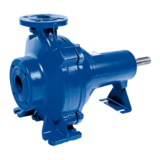
Figure V Pump with bare shaft at the drive end, sole plate and suction elbow 4.2 Product information as per Regulation No. 1907/2006 (REACH) For information as per European chemicals regulation (EC) No. 1907/2006 (REACH) see https://www.ksb.com/en-global/company/corporate-responsibility/reach. Sewatec 16 of 94... -
Page 17: Designation
4 Description of the Pump (Set) 4.3 Designation Example: Sewatec F 100-250G V Table 6: Designation key Code Description Sewatec Type series Impeller type Nominal discharge nozzle diameter [mm] Nominal impeller diameter [mm] Material variant Installation type 4.4 Name plate KSB SE & Co. KGaA Johann-Klein-Straße 9... -
Page 18: Design And Function
(9 and 10), which are supported by a bearing bracket (5) linked with the pump casing and/or casing cover. Sealing The pump is sealed by two bi-directional mechanical seals in tandem arrangement. A lubricant reservoir in-between the seals ensures cooling and lubrication of the mechanical seals. Sewatec 18 of 94... -
Page 19: Noise Characteristics
NOTE Some individual components weigh more than 25 kg. Check the indicated weights. (ð Section 1.4, Page 7) Measured at a distance of 1 m from the pump outline (as per DIN 45635 Parts 1 and 24) For nominal discharge nozzle diameter ≥ DN 100 Sewatec 19 of 94... -
Page 20: Installation At Site
▷ Make sure that the connection between pump and baseplate is electrically conductive. ▷ Screws, bolts, nuts and shims must not be coated or the coating must be removed. ▷ Provide potential equalisation between the pump set and the foundation. Sewatec 20 of 94... - Page 21 5. Insert threaded rods into the corresponding drilled holes with an electric tool (e.g. impact drill, hammer drill). 6. After the curing time (see table), tighten the chemical anchors (4) evenly and tightly. 7. Grout the baseplate using low-shrinkage concrete. Chemical anchor dimensions Fig. 4: Dimensions Sewatec 21 of 94...
-
Page 22: Piping
▷ Observe the permissible forces and moments at the pump nozzles. ▷ Take appropriate measures to compensate for thermal expansion of the piping. SW = Width across flats Mounting accessories of the respective manufacturer are required. Sewatec 22 of 94... -
Page 23: Permissible Forces And Moments At The Pump Nozzles
Fig. 5: Forces and moments at the pump nozzles for horizontal installation, bare- shaft pump (Figure 0) The loads are taken from ISO 5199. The values are applicable to each of the pump nozzles, taking into account the markings for the three axes of the respective flange. Sewatec 23 of 94... - Page 24 1300 150-317 2100 1900 2350 3650 1150 1700 1400 1750 1600 2750 1300 150-317 1600 1400 1750 2750 1300 1400 1750 1600 2750 1300 150-400 2100 1900 2350 3650 1150 1700 1400 1750 1600 2750 1300 Sewatec 24 of 94...
- Page 25 Table 10: Forces and moments at the pump nozzles, vertical installation, with soleplate Flanges Forces at suction nozzle Moments at suction Forces at discharge Moments at discharge nozzle nozzle nozzle ∑F ∑M ∑F ∑M [Nm] [Nm] 50-215 1150 50-216 1150 50-250 1150 50-251 1150 65-215 1400 1150 Sewatec 25 of 94...
- Page 26 1900 2350 2100 3650 1150 1700 2350 1900 2100 3650 1150 1700 200-318 1900 2350 2100 3650 1150 1700 2350 1900 2100 3650 1150 1700 Fig. 7: Forces and moments at the pump nozzles, vertical installation, with suction elbow Sewatec 26 of 94...
- Page 27 5400 6700 6000 10450 2300 2650 3250 4800 2350 1900 2100 3650 1150 1700 200-317 5400 6700 6000 10450 2300 2650 3250 4800 2350 1900 2100 3650 1150 1700 200-318 5400 6700 6000 10450 2300 2650 3250 4800 2350 1900 2100 3650 1150 1700 Sewatec 27 of 94...
-
Page 28: Vacuum Balance Line
Risk of injuries by parts flying off and escaping fluid! ▷ Never use screw plugs for releasing pressure from the pump casing. ▷ Always use suitable venting devices (e.g. vent valve). The following auxiliary connections are available: Sewatec 28 of 94... -
Page 29: Checking The Coupling Alignment
5.6 Checking the coupling alignment DANGER Inadmissible temperatures at the coupling or bearings due to misalignment of the coupling Explosion hazard! Risk of burns! ▷ Make sure that the coupling is correctly aligned at all times. For vertical installation only Sewatec 29 of 94... - Page 30 ▷ Also check the coupling of pump sets supplied with pump and motor mounted on the same baseplate. Fig. 10: Non-spacer-type coupling, checking the coupling alignment Straight edge Gauge Fig. 11: Spacer-type coupling, checking the coupling alignment Straight edge Gauge Sewatec 30 of 94...
- Page 31 5. If alignment is correct, re-install the coupling guard and its footboard, if any. Checking the coupling alignment with a laser tool Coupling alignment may also be checked with a laser tool. Observe the documentation provided by the manufacturer of the measuring instrument. Sewatec 31 of 94...
-
Page 32: Checking The Belt Drive
> 200 2,45 < 160 2,55 > 160 < 224 2,55 > 224 < 355 1000 2,25 1,85 > 355 1,75 180 < 250 2,55 > 250 < 355 2,05 > 355 < 560 > 560 Sewatec 32 of 94... -
Page 33: Aligning The Pump And Motor
Risk of injury by rotating shafts! ▷ Always operate the pump set with a coupling guard. If the customer specifically requests not to include a coupling guard in KSB's delivery, then the operator must supply one! ▷ Observe all relevant regulations for selecting a coupling guard. -
Page 34: Checking The Lubricants
▷ Observe regulations IEC 60364 and, for explosion-proof versions, EN 60079 . DANGER Incorrect electrical installation Danger of death from electric shock! ▷ For electrical installation, also observe the requirements of IEC 60079-14. ▷ Always connect explosion-proof motors via a motor protection switch. Sewatec 34 of 94... -
Page 35: Checking The Direction Of Rotation
The motor's direction of rotation must match the arrow indicating the direction of rotation on the pump. 3. If the motor is running in the wrong direction of rotation, check the electrical connection of the motor and switchgear, if any. Sewatec 35 of 94... -
Page 36: Priming And Venting The Pump
The pump is supplied prepared for the connection of resistance thermometers as an option. Fasten the resistance thermometers at the points indicated at the bearing bracket. Observe the technical literature of the sensor for fastening and electrical wiring. Sewatec 36 of 94... -
Page 37: Warning And Trip Values
Within the preferred operating range of 0.7 ≤ Q/QBEP ≤ 1.2 the vibration values of newly commissioned pumps with good system conditions (piping layout, approach flow at the pump, etc.) are below the limits of zone A to DIN ISO 10816-7, i.e. below 3.5 mm/s rms. Sewatec 37 of 94... -
Page 38: Commissioning/Start-Up/Shutdown
▷ If the pump is in slurp mode, stop the pump immediately. WARNING Pump sets with high noise levels Damage to hearing! ▷ Persons must only enter the vicinity of the running pump set if they are wearing protective clothing/ear protection. ▷ See noise characteristics. (ð Section 4.7, Page 19) Sewatec 38 of 94... -
Page 39: Shutdown
▷ Avoid prolonged operation against a closed shut-off element. ▷ Never operate the pump at temperatures, pressures or rotational speeds exceeding those specified in the data sheet or on the name plate unless the written consent of the manufacturer has been obtained. Sewatec 39 of 94... -
Page 40: Maximum Operating Pressure, Maximum Test Pressure
D 100 - 251 100 - 252 100 - 253 D 100 - 253 100 - 254 100 - 315 100 - 316 D 100 - 316 100 - 317 10,5 K 100 - 400 100 - 401 Sewatec 40 of 94... -
Page 41: Frequency Of Starts
▷ Observe the temperature limits in the data sheet and in the section on operating limits. (ð Section 6.2, Page 39) 6.2.3.2 Density of the fluid handled The power input of the pump set will change in proportion to the density of the fluid handled. Sewatec 41 of 94... -
Page 42: Abrasive Fluids
6.4 Returning to service For returning the equipment to service, observe the sections on commissioning/start- up (ð Section 6.1, Page 38) and the operating limits (ð Section 6.2, Page 39) . In addition, carry out all servicing/maintenance operations before returning the pump (set) to service. (ð Section 7, Page 44) Sewatec 42 of 94... - Page 43 Risk of injury from moving parts or escaping fluid! ▷ As soon as the work is completed, properly re-install and re-activate any safety- relevant devices and protective devices. NOTE On pumps/pump sets older than 5 years we recommend replacing all elastomer seals. Sewatec 43 of 94...
-
Page 44: Servicing/Maintenance
Fluids handled, consumables and supplies which are hot and/or pose a health hazard Risk of injury! ▷ Observe all relevant laws. ▷ When draining the fluid take appropriate measures to protect persons and the environment. ▷ Decontaminate pumps which handle fluids posing a health hazard. Sewatec 44 of 94... -
Page 45: Servicing/Inspection
NOTE All maintenance work, service work and installation work can be carried out by KSB Service or authorised workshops. For contact details refer to the enclosed "Addresses" booklet or visit "https://www.ksb.com/en-global/contact" on the Internet. -
Page 46: Inspection Work
▷ Never insert your hands or any other objects into the pump, if the pump set has not been disconnected from the power supply and secured against unintentional start-up. If a problem has occurred which requires visual inspection, observe the following instructions: Sewatec 46 of 94... -
Page 47: Lubrication And Lubricant Change
The rolling element bearings of the pump sets are grease-packed and maintenance- free. 7.2.3.2 Changing the lubricant of the mechanical seal DANGER Excessive temperatures in the shaft seal area Explosion hazard! Damage to the pump set! ▷ Regularly check the lubricant level. Sewatec 47 of 94... - Page 48 2. Fill the lubricant reservoir up to the filler opening. 3. Fit screw plug 903.90 with joint ring 411.90. Fig. 21: Filling in the lubricant Intervals Change the lubricant every 10,000 operating hours, but at least every three years. Sewatec 48 of 94...
-
Page 49: Lubricant Quantity
150 - 317 150 - 400 150 - 401 150 - 403 200 - 315 200 - 316 200 - 317 200 - 318 200 - 402 200 - 403 250 - 401 250 - 403 Sewatec 49 of 94... -
Page 50: Lubricant Quality
For any work on the motor, observe the instructions of the relevant motor manufacturer. For dismantling and reassembly observe the exploded view and the general assembly drawing. In case of damage you can always contact our service departments. Sewatec 50 of 94... -
Page 51: Preparations For Dismantling
The pump casing can remain installed in the piping for further dismantling. 1. Disconnect the power supply (e.g. at the motor). 2. Disconnect and remove all auxiliary pipework. 3. Remove coupling guard 681. 4. Remove the coupling spacer of coupling 848, if any. 5. Drain the oil. Sewatec 51 of 94... -
Page 52: Separating The Pump From The Piping
Work in the area of the V-belts Injury by moving parts! ▷ Make sure that the pump set cannot be switched on. DANGER Unsecured dismantled components Injury by falling parts! ▷ Secure all dismantled components or assemblies against moving or tipping over. Sewatec 52 of 94... -
Page 53: Using Taper Clamping Bushes
7.4.4.2 Using pulleys to DIN 2211 ü Dismantling steps 1 to 3 have been completed. 1. Use a puller to remove the pulleys from the shaft. NOTE The puller is not included in the scope of supply. Sewatec 53 of 94... -
Page 54: Removing The Back Pull-Out Unit
3. Use a forcing screw to pull off impeller 230. Fig. 24: Removing the impeller NOTE The forcing screw is not included in the scope of supply. It can be ordered separately from KSB. Table 19: Forcing screws for pulling off the impeller Size Impeller type Forcing screw (ADS) - Page 55 M 24 ADS 5 150-401 E, F M 20 ADS 5 150-403 M 24 ADS 5 150-403 M 24 ADS 5 151-403 M 24 ADS 5 200-315 M 20 ADS 2 200-315 M 20 ADS 4 Sewatec 55 of 94...
-
Page 56: Dismantling The Mechanical Seal
7.4.7.2 Dismantling the motor-end mechanical seal ü The back pull-out unit and the impeller have been removed as described above. 1. Remove locking ring 515 or circlip 932.03. 2. Pull the rotating assembly of mechanical seal 433.01 off shaft 210. Sewatec 56 of 94... -
Page 57: Removing The C022/025/11-4Stq Double Cartridge Seal
4. Clean the pump components in the area of the mechanical seal, pump shaft 210, discharge cover 163 and bearing bracket 330. Check for any damage. Further dismantling of the mechanical seal is carried out at KSB. Sewatec 57 of 94... -
Page 58: Removing Shaft And Rolling Element Bearings
5. Remove the stationary seat of drive-end mechanical seal 433.01 from bearing bracket 330. 6. Clean all components and inspect them for signs of wear. CAUTION Re-installing damaged components Damage to the machine! ▷ Re-work damaged components or replace by new ones. Sewatec 58 of 94... -
Page 59: Removing The Wear Plate (For D Impeller Only)
ü The wear plate needs to be replaced as a result of visual inspection. 1. Unbolt the pump casing from the piping. 2. Undo hexagon socket head cap screws 914.12. 3. Remove wear plate 135.01 and O-rings 412.34. Sewatec 59 of 94... -
Page 60: Reassembling The Pump Set
Checking the alignment After assembly with the pump casing that has remained in the piping, check the coupling alignment. (ð Section 5.6, Page 29) 7.5.2 Re-installing the shaft and rolling element bearings When re-installing the shaft, replace deep groove ball bearings 321.01/02, if required. (ð Section 7.5.1, Page 60) Sewatec 60 of 94... -
Page 61: Installing The Mechanical Seal
▪ To prevent any damage to the rubber bellows, place a thin foil (of approximately 0.1 to 0.3 mm thickness) around the free shaft stub. Slide the rotating assembly over the foil into its installation position. Then remove the foil. Sewatec 61 of 94... -
Page 62: Installing The Bellows-Type Mechanical Seal
050 - 250 F, K 29,0 050 - 251 F, K 38,5 065 - 215 29,0 065 - 216 38,5 065 - 217 29,0 065 - 250 F, K 29,0 065 - 253 38,5 080 - 215 29,0 Sewatec 62 of 94... - Page 63 200 - 402 K, D 48,3 200 - 403 48,3 200 - 405 48,3 250 - 401 48,3 250 - 402 48,3 250 - 403 48,3 300 - 400 48,3 300 - 401 48,3 300 - 402 48,3 Sewatec 63 of 94...
-
Page 64: Installing The C022/025M1-4Stq Double Cartridge Seal
ü The back pull-out unit of the pump has been placed in a clean and level assembly area. ü The KSB 4STQ double cartridge seal is fully assembled and undamaged. 1. Insert circlip 932.59 in the shaft groove and make sure that circlip 932.59 is positioned correctly in the shaft groove. - Page 65 "K") and correct the installation position if required. 5. Slide O-ring 412.28 over shaft, until it abuts against the mechanical seal. Fig. 35: Mounting device 101-47 Fig. 36: Reference dimension "K” from shaft end to KSB double cartridge seal Table 22: Reference dimension "K" Size Reference dimension "K"...
-
Page 66: Installing The C033/055M1-4Stq Double Cartridge Seal
ü The original 4STQ cartridge seal is fully assembled and undamaged. ü Mounting device C is available. 1. Guide the mechanical seal (without external O-rings) onto the shaft as far as it will go. Sewatec 66 of 94... - Page 67 4. Fit the circlip in the shaft groove. Fig. 38: Marking the shaft end 5. Mark the front face of shaft end A. To do so extend the central position of ring opening B in the axial direction. Fig. 39: Marking the mechanical seal Sewatec 67 of 94...
- Page 68 8. Place the mechanical seal on the shaft. Guide it as far into the discharge cover as possible. Verify that the markings A are aligned with each other. Fig. 41: Mounting device C Fig. 42: Reference dimension "K” from shaft end to mechanical seal Sewatec 68 of 94...
-
Page 69: Fitting The Impeller
Table 23: Tightening torque for impeller screw [Nm] Size Impeller type Thread Tightening torque [Nm] 050 - 215 050 - 216 050 - 250 F, K M 10 050 - 251 F, K M 16 065 - 215 Sewatec 69 of 94... - Page 70 M 20 200 - 405 M 20 250 - 401 M 20 250 - 402 M 20 250 - 403 M 20 300 - 400 M 20 300 - 401 M 20 300 - 402 M 20 Sewatec 70 of 94...
-
Page 71: Installing The Back Pull-Out Unit
Note: Make sure that the tapered fit of impeller and shaft is undamaged and assembled free from grease. For size Sewatec D 150-251 first screw screwed coupling 852 into the shaft. 7.5.5 Installing the back pull-out unit WARNING Back pull-out unit tilting Risk of crushing hands and feet! ▷... -
Page 72: Leak Test
ð The pressure must not drop during the test period. ð If the pressure does drop, check the seals and screwed connections. Then perform another leak test. 3. Once the leak test has been successful, fill in the lubricant. (ð Section 7.2.3.2, Page 47) Sewatec 72 of 94... -
Page 73: Mounting The Motor
1. Use bushing 540.03 to fit pulley 882.02 on the motor shaft. 2. Fit bushing 540.02 on pump shaft 210. 3. Place pulley 882.01 on bushing 540.02. 4. Pull V-belts on pulleys 882.01/882.02. 5. Check the alignment of the pulleys. 6. Tension the V-belts. (ð Section 5.7.2, Page 32) Sewatec 73 of 94... -
Page 74: Using Taper Clamping Bushes
Fill any open connection holes with grease to prevent the ingress of foreign matter. 7.5.8.2 Using pulleys to DIN 2211 Use a pneumatic or hydraulic puller to fit the pulleys. Watch the position of the key. Secure the pulley axially with a grub screw. Sewatec 74 of 94... -
Page 75: Tightening Torques
Refer to the name plate for all data. Also specify the following data: ▪ Part No. and description (ð Section 9.3, Page 81) ▪ Quantity of spare parts ▪ Shipping address ▪ Mode of dispatch (freight, mail, express freight, air freight) Sewatec 75 of 94... -
Page 76: Recommended Spare Parts Stock For 2 Years' Operation To Din 24296
▪ Shaft protecting sleeve ▪ Lantern ring Packing cord (4 rings) 100 % ✘ Sealing elements (set) 150 % ✘ Keeping a stock of wear parts and replacement parts is recommended also during the warranty period. Sewatec 76 of 94... -
Page 77: Trouble-Shooting
If problems occur that are not described in the following table, consultation with the KSB service is required. A Pump delivers insufficient flow rate B Motor is overloaded... - Page 78 - Pump back pressure is lower than Re-adjust to duty point. specified in the purchase order. ✘ - Density or viscosity of the fluid handled Contact KSB. is higher than stated in the purchase order. - Speed is too high. Reduce speed, request particulars.
-
Page 79: Related Documents
0,0048 3000 0,0059 3000 0,0075 0,014 3000 0,0097 0,017 3000 0,013 0,021 3000 0,018 0,028 3000 0,034 3000 0,030 0,044 3000 0,055 3000 0,034 0,07 10,5 3000 0,089 12,2 3000 0,048 0,11 3000 0,17 19,5 3000 Sewatec 79 of 94... - Page 80 50 mm (SPA - 3 grooves) 100 mm (SPA - 5 grooves) [rpm] [kgm [kg] [kgm [kg] [mm] 0,068 0,21 22,5 3000 0,097 0,23 2700 0,16 0,34 2700 0,163 0,48 25,5 2200 0,244 0,57 31,5 1900 Without locking sleeve Sewatec 80 of 94...
-
Page 81: General Assembly Drawings/Exploded Views With List Of Components
433.01 903.22 Fig. 47: General assembly drawing of Sewatec - with bearing brackets S01, S02, S03, S04, impeller type E; * if any, ** only for sizes E 100-250, E 100-253, E 100-317, E 150-317, K 100-253, K 100-254, K 100-316 Table 30: List of components... -
Page 82: Detail Drawings
Part No. Description 13-6 Casing insert Casing wear ring Impeller wear ring 914.12 412.34 914.10 550.23 914.24 Fig. 51: D impeller (single-vane impeller) and D impeller (multi-vane impeller) Only for Sewatec 100-401 and 200-400 Not for Sewatec 100-401 Sewatec 82 of 94... -
Page 83: Inspection Hole, Bearing Brackets S01 To S04
9.3.2.2 Inspection hole, bearing brackets S01 to S04 900.02 920.17 550.04 164.02 412.05 Fig. 52: Inspection hole, bearing brackets S01 to S04 Table 34: List of components Part No. Description Part No. Description 164.02 Inspection cover 900.02 Bolt/screw 412.05 O-ring 920.17 550.04 Disc Sewatec 83 of 94... -
Page 84: Sectional Drawings Of The Mechanical Seal
411.22 4.01** Fig. 54: Pump-end mechanical seal 12.04 Table 36: List of components 412.15 411.46 903.46 433.01 903.22 433.02 Part No. Description 433.02 Mechanical seal 903.01 411.01 515 / 932.03 932.20 411.22 412.04 412.15 411.46 903.46 433.01 903.22 Sewatec 84 of 94... -
Page 85: Cartridge Seal C022/025M1-4Stq
Ring 472.53/.55 Primary ring Disc Primary ring carrier 562.52/.55 Parallel pin 474.53/.55 Thrust ring 904.53 Grub screw 475.52 Mating ring 914.52 Hexagon socket head cap screw Mating ring carrier 932.52/.53/.59 Circlip 477.53/.55 Spring for mechanical seal Sewatec 85 of 94... -
Page 86: Cartridge Seal C033/055M1-4Stq
O-ring 477.52/.53 Spring for mechanical seal 57/.58/.59 441.52/.53 Shaft seal housing Ring 472.52/.53 Primary ring Shaft sleeve Thrust ring 562.52/.53/.54/.55 Parallel pin 475.52/.53 Mating ring 914.52 Hexagon socket head cap screw Mating ring carrier 932.52 Circlip Sewatec 86 of 94... - Page 87 412.04 411.22 433.01 903.22 903.46 411.46 433.02 852* 550.23 914.10 Fig. 57: Exploded view of the pump; * For Sewatec D 150-251 a screwed coupling (852) is used in this position. 81-33 901.59 550.59 901.69 550.69 882.02 540.16 920.65 884.01 882.01 901.65...
- Page 88 Hexagon head bolt Bearing bracket 902.01 Stud 360.02 Bearing cover 903.01/.02/.03/.22/.46/.90 Screw plug 411.01/.02/.03/.22/.46/.90 Joint ring 914.10 Hexagon socket head cap screw 412.04/.15 O-ring 920.01/.65 433.01/.02 Mechanical seal 932.02/.20 Circlip Casing wear ring 940.02 Locking ring Sewatec 88 of 94...
-
Page 89: Eu Declaration Of Conformity
10 EU Declaration of Conformity 10 EU Declaration of Conformity Manufacturer: KSB SE & Co. KGaA Johann-Klein-Straße 9 67227 Frankenthal (Germany) The manufacturer herewith declares that the product: Sewabloc, Sewatec, Sewatec SPN KSB order number: ....................▪ is in conformity with the provisions of the following directives / regulations as amended from time to time: –... -
Page 90: Certificate Of Decontamination
We confirm that the above data and information are correct and complete and that dispatch is effected in accordance with the relevant legal provisions....................................Place, date and signature Address Company stamp Required field Sewatec 90 of 94... -
Page 91: Index
Fluid handled Density 41 Frequency of starts 41 Warnings 8 Warranty claims 7 Impeller type 17 Installation Installation on a foundation 21 Installation at site 20 Intended use 9 Key to safety symbols/markings 8 Lubricant Quantity 49 Maintenance 45 Operating limits 39, 45 Order number 7 Other applicable documents 7 Sewatec 91 of 94... - Page 94 KSB SE & Co. KGaA Johann-Klein-Straße 9 • 67227 Frankenthal (Germany) Tel. +49 6233 86-0 www.ksb.com...
Need help?
Do you have a question about the Sewatec and is the answer not in the manual?
Questions and answers