
Related Manuals for KSB Sewatec Series


Summary of Contents for KSB Sewatec Series
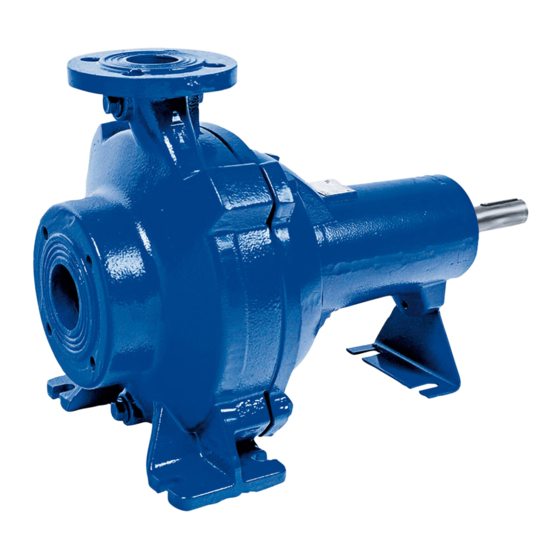
- Page 1 Dry-installed Volute Casing Pump Sewatec (60 Hz) 60 Hz ASME / NEMA Motors Bearing Brackets S01, S02, S03, S04 Installation/Operating Manual...
- Page 2 All rights reserved. The contents provided herein must neither be distributed, copied, reproduced, edited or processed for any other purpose, nor otherwise transmitted, published or made available to a third party without the manufacturer's express written consent. Subject to technical modification without prior notice. © KSB SE & Co. KGaA, Frankenthal 4/4/2018...
-
Page 3: Table Of Contents
Contents Contents Glossary .............................. 5 General.............................. 6 Principles ................................ 6 Installation of partly completed machinery.................... 6 Target group.............................. 6 Other applicable documents.......................... 6 Symbols ................................ 6 Safety .............................. 8 Key to safety symbols/markings........................ 8 General................................ 8 Intended use .............................. 8 Personnel qualification and personnel training ..................... 9 Consequences and risks caused by non-compliance with these operating instructions ...... 10 Safety awareness ............................ 10 Safety information for the operator/user ..................... 10 Safety information for maintenance, inspection and installation .............. 10... - Page 4 Contents 5.15 Warning values and cut-out values ....................... 31 Commissioning/Start-up/Shutdown.................... 33 Commissioning/start-up .......................... 33 6.1.1 Prerequisites for commissioning/start-up .................. 33 6.1.2 Start-up............................... 33 6.1.3 Shutdown ............................ 34 Operating limits.............................. 34 6.2.1 Maximum operating pressure ...................... 35 6.2.2 Frequency of starts.......................... 36 6.2.3 Fluid handled ............................. 36 Shutdown/storage/preservation ........................ 37 Returning to service after storage......................... 37 Servicing/Maintenance ........................
-
Page 5: Glossary
Glossary Glossary Back pull-out design The complete back pull-out unit can be pulled out without having to remove the pump casing from the piping. Certificate of decontamination If a product is to be returned to the manufacturer, the customer declares in a certificate of decontamination that the product has been properly drained to eliminate any environmental and health hazards arising from components in... -
Page 6: General
In the event of damage, immediately contact your nearest KSB Service center to maintain the right to claim under warranty. 1.2 Installation of partly completed machinery To install partly completed machinery supplied by KSB refer to the sub-sections under Servicing/Maintenance. - Page 7 1 General Symbol Description Step-by-step instructions Note Recommendations and important information on how to handle the product Sewatec (60 Hz) 7 of 72...
-
Page 8: Safety
2 Safety 2 Safety All the information contained in this section refers to hazardous situations. DANGER In addition to the present general safety information the action-related safety information given in the other sections must be observed. 2.1 Key to safety symbols/markings Table 3: Definition of safety symbols/markings Symbol Description... -
Page 9: Personnel Qualification And Personnel Training
2 Safety ▪ Observe the limits for continuous duty specified in the data sheet or product literature (Q and Q ) (to prevent damage such as shaft fracture, bearing failure, mechanical seal damage, etc). ▪ When untreated waste water is handled, the duty points in continuous operation lie within 0.7 to 1.2 × Q to minimize the risk of clogging/hardening. -
Page 10: Consequences And Risks Caused By Non-Compliance With These Operating Instructions
2 Safety 2.5 Consequences and risks caused by non-compliance with these operating instructions ▪ Non-compliance with these operating instructions will lead to forfeiture of warranty cover and of any and all rights to claims for damages. ▪ Non-compliance can, for example, have the following consequences: –... -
Page 11: Unauthorized Modes Of Operation
2 Safety ▪ When taking the pump set out of service always adhere to the procedure described in the manual. ▪ Decontaminate pumps which handle fluids posing a health hazard. (ð Section 7.3, Page 43) ▪ As soon as the work has been completed, re-install and re-activate any safety- relevant devices and protective devices. -
Page 12: Transport/Temporary Storage/Disposal
1. On transfer of goods, check each packaging unit for damage. 2. In the event of in-transit damage, assess the exact damage, document it and notify KSB or the distributor and the insurance company about the damage in writing immediately. -
Page 13: Storage/Preservation
3 Transport/Temporary Storage/Disposal Transporting the pump set on the Transporting a bare-shaft pump on the baseplate baseplate 3.3 Storage/Preservation If commissioning is to take place some time after delivery, we recommend that the following measures be taken for pump set storage: CAUTION Damage during storage due to humidity, dirt or vermin Corrosion/contamination of the pump (set)! -
Page 14: Disposal
3 Transport/Temporary Storage/Disposal NOTE If required, a blank certificate of decontamination can be downloaded from the KSB web site at: www.ksb.com/certificate_of_decontamination 3.5 Disposal WARNING Fluids handled, consumables and operating supplies which are hot or pose a health hazard Hazard to persons and the environment! ▷... -
Page 15: Description Of The Pump (Set)
4 Description of the Pump (Set) 4 Description of the Pump (Set) 4.1 General description Pump for handling untreated sewage and all types of waste water. ▪ Volute casing pump with single-vane, multi-channel, free flow or open diagonal single-vane impeller ▪... -
Page 16: Name Plate
4 Description of the Pump (Set) 4.3 Name plate KSB SE & Co. KGaA Johann-Klein-Straße 9 67227 Frankenthal Deutschland 2008 Sewatec D 300 - 400 P-No. 9971423078 / 000100 Q 306,44 GPM H 5,29 ft n 983 rpm SNr. 24 15 26 Mat.-No. -
Page 17: Configuration And Function
4 Description of the Pump (Set) 4.5 Configuration and function Fig. 2: Sectional drawing with K impeller Clearance gap Discharge nozzle Discharge cover Shaft Bearing bracket Suction nozzle Impeller Shaft seal Rolling element bearing Rolling element bearing Design The pump is designed with an axial fluid inlet and a radial or tangential outlet. The hydraulic system runs in its own bearings and is connected to the motor by a shaft coupling or belt drive. -
Page 18: Scope Of Supply
4 Description of the Pump (Set) Rated power input Pump Pump set 1750 rpm 1160 / 875 rpm 1750 rpm 1160 / 875 rpm [dB] [dB] [dB] [dB] 4 hp (3,0 kW) 55,0 53,5 60,5 59,0 5 hp (4,0 kW) 57,0 55,0 62,0... -
Page 19: Installation At Site
5 Installation at Site 5 Installation at Site 5.1 Safety regulations DANGER Improper installation in potentially explosive atmospheres Damage to the pump set! ▷ Comply with the applicable local explosion protection regulations. ▷ Observe the information given in the data sheet and on the pump/motor name plates. - Page 20 5 Installation at Site 3. Drill the holes as specified in the table "Chemical anchor dimensions". Then clean the holes. WARNING Improper handling of mortar cartridge Skin sensitization and/or irritation! ▷ Wear suitable protective clothing. 4. Insert the mortar cartridges into the drilled holes. Observe the curing times of the mortar cartridges! 5.
-
Page 21: Piping
5 Installation at Site Table 11: Curing times of mortar cartridge Floor temperature Curing time [°F] [°C] [min] 23 to 32 -5 to 0 32 to 50 0 to +10 50 to 68 +10 to +20 > 68 > +20 5.4 Piping NOTE When installing pumps in a piping system prevent any resonances at the usual excitation frequencies (1x and 2x rotational frequency, rotational noise) in the... -
Page 22: Permissible Forces And Moments At The Pump Nozzles
The data on forces and moments apply to static piping loads only. If the limits are exceeded, they must be checked and verified. If a computerized strength analysis is required, please contact KSB. The values are only applicable if the pump is installed on a completely grouted baseplate and bolted to a rigid and level foundation. - Page 23 5 Installation at Site Flanges Forces at suction nozzle Moments at suction Forces at discharge Moments at discharge nozzle nozzle nozzle DN1 DN2 Fy ∑F ∑M ∑F ∑M [lbs] [ft lbs] [lbs] [ft lbs] 100 - 253 S02 150 100 - 254 S01 100 100 - 254 S01 100...
- Page 24 5 Installation at Site Table 13: Forces and moments at the pump nozzles, Sewatec S01 to S03, vertical installation Flanges Forces at suction nozzle Moments at suction Forces at discharge Moments at discharge nozzle nozzle nozzle DN1 DN2 Fy ∑F ∑M ∑F ∑M [lbs]...
-
Page 25: Vacuum Balance Line
5 Installation at Site 5.4.3 Vacuum balance line NOTE Where fluid has to be pumped out of a vessel under vacuum, installing a vacuum balance line is recommended. The following rules apply to vacuum balance lines: ▪ Minimum nominal line diameter: 0.98 inch [25 mm]. ▪... -
Page 26: Checking The Coupling Alignment
5 Installation at Site 1M.1 1M.1 1M.2/6D Fig. 6: Auxiliary connections Table 14: Sizes of auxiliary connections Size 050 - 215 065 - 215 080 - 215 125 - 315 100 - 401 K 150 - 400 200 - 330 050 - 216 065 - 216 080 - 216 125 - 317... -
Page 27: Aligning The Pump And Motor
5 Installation at Site CAUTION Misalignment of pump and motor shafts Damage to pump, motor and coupling! ▷ Always check the coupling after the pump has been installed and connected to the piping. ▷ Also check the coupling if pump sets are supplied with pump and motor mounted on the same baseplate. -
Page 28: Motors With Adjusting Screw
Risk of injury by rotating shafts! ▷ Always operate the pump set with a coupling guard. If the customer specifically requests not to include a coupling guard in KSB's delivery, then the operator must supply one! ▷ Observe all relevant regulations for selecting a coupling guard. -
Page 29: Electrical Connection
5 Installation at Site Fig. 9: Checking the lubricant level ü The pump set has been installed as described in this manual. 1. Unscrew and remove screw plug (1) with joint ring (2). 2. If the lubricant level is within the tolerance range of 0.39 inch (10 mm) below the opening, re-insert and fasten screw plug (1) with joint ring (2). -
Page 30: Checking The Direction Of Rotation
5 Installation at Site 5.10 Checking the direction of rotation DANGER Temperature increase resulting from contact between rotating and stationary components Damage to the pump set! ▷ Never check the direction of rotation by starting up the unfilled pump set. ▷... -
Page 31: Protective Equipment
5 Installation at Site 5.12 Protective equipment WARNING Failure to re-install or re-activate protective equipment/devices Risk of personal injury from moving parts or escaping fluid! ▷ As soon as the work is completed, re-install and/or re-activate any safety- relevant devices and protective devices. 5.13 Connecting the vibration sensor The pump is supplied prepared for the connection of a vibration sensor as an option. - Page 32 5 Installation at Site Table 15: Warning values and cut-out values Sensors Warning value Cut-out value Vibrations in/s 0,248 0,374 mm/s Bearing temperature at the outer bearing ring °F °C Sewatec (60 Hz) 32 of 72...
-
Page 33: Commissioning/Start-Up/Shutdown
6 Commissioning/Start-up/Shutdown 6 Commissioning/Start-up/Shutdown 6.1 Commissioning/start-up 6.1.1 Prerequisites for commissioning/start-up Before commissioning/starting up the pump set, make sure that the following conditions are met: ▪ The pump set has been properly connected to the electric power supply and is equipped with all protection devices. ▪... -
Page 34: Shutdown
6 Commissioning/Start-up/Shutdown WARNING Abnormal noises, vibrations, temperatures or leakage Damage to the pump! Risk of personal injury! ▷ Switch off the pump (set) immediately. ▷ Eliminate the causes before returning the pump set to service. ü The pump, suction line and discharge line have been vented and primed with the fluid to be handled. -
Page 35: Maximum Operating Pressure
6 Commissioning/Start-up/Shutdown 6.2.1 Maximum operating pressure CAUTION Non-compliance with permissible operating pressure Damage to connections and seals! ▷ Never exceed the operating pressure specified in the data sheet. Table 16: Maximum operating pressure, maximum test pressure Size Maximum operating pressure Maximum test pressure [psi] [bar] [psi]... -
Page 36: Frequency Of Starts
6 Commissioning/Start-up/Shutdown Size Maximum operating pressure Maximum test pressure [psi] [bar] [psi] [bar] 150 - 401 150 - 403 151 - 403 200 - 315 200 - 316 200 - 317 200 - 318 200 - 330 300 - 401 K 200 - 402 200 - 403 250 - 400... -
Page 37: Shutdown/Storage/Preservation
6 Commissioning/Start-up/Shutdown 6.2.3.3 Abrasive fluids Do not exceed the maximum permissible solids content specified in the data sheet. When the pump handles fluids containing abrasive substances, increased wear of the hydraulic system and the shaft seal is to be expected. In this case, halve the intervals commonly recommended for servicing and maintenance. -
Page 38: Servicing/Maintenance
7 Servicing/Maintenance 7 Servicing/Maintenance 7.1 Safety regulations DANGER Sparks produced during maintenance work Explosion hazard! ▷ Observe the safety regulations in force at the place of installation. ▷ Never open a pump set that is connected to the power supply. ▷... -
Page 39: Maintenance/Inspection
7 Servicing/Maintenance NOTE All maintenance work, service work and installation work can be carried out by KSB Service or authorized workshops. Find your contact in the attached "Addresses" booklet or on the Internet at "www.ksb.com/contact". Never use force when dismantling and reassembling the pump set. - Page 40 7 Servicing/Maintenance WARNING Fluids handled, consumables and operating supplies which are hot or pose a health hazard Hazard to persons and the environment! ▷ Collect and properly dispose of the flushing fluid and of any residues of the fluid handled. ▷...
-
Page 41: Lubrication And Lubricant Change
7 Servicing/Maintenance 7.2.3 Lubrication and lubricant change DANGER Excessive temperatures as a result of bearings running hot or defective bearing seals Fire hazard! Damage to the pump set! ▷ Regularly check the rolling element bearings for running noises. 7.2.3.1 Lubricating the rolling element bearings The rolling element bearings of the pump sets are grease-packed and maintenance- free. - Page 42 7 Servicing/Maintenance Filling in the lubricant 903.90 903.46 903.22 1. Unscrew and remove screw plug 903.90 with joint ring 411.90. 411.90 411.46 411.22 2. Fill the lubricant chamber up to the filler opening. 3. Re-insert and tighten screw plug 903.90 with joint ring 411.90. 7.2.3.3 Lubricant quantity Fig. 14: Filling in the lubricant...
-
Page 43: Drainage/Disposal
7 Servicing/Maintenance Size Bearing bracket Lubricant quantity [quart] 150 - 403 151 - 403 200 - 315 200 - 316 200 - 317 200 - 318 200 - 330 200 - 401 200 - 402 200 - 403 250 - 400 250 - 401 250 - 403 300 - 400... -
Page 44: Dismantling The Pump Set
7 Servicing/Maintenance 7.4 Dismantling the pump set 7.4.1 General information/Safety regulations WARNING Unqualified personnel performing work on the pump (set) Risk of personal injury! ▷ Always have repair work and maintenance work performed by specially trained, qualified personnel. WARNING Improper lifting/moving of heavy assemblies or components Personal injury and damage to property! ▷... -
Page 45: Separating The Pump From The Piping
7 Servicing/Maintenance WARNING Components with sharp edges Risk of cutting or shearing injuries! ▷ Always use appropriate caution for installation and dismantling work. ▷ Wear work gloves. NOTE For further dismantling the pump casing may remain installed in the piping. 1. -
Page 46: Removing The Impeller
3. Pull off impeller 230 with a forcing screw. Fig. 16: Removing the impeller NOTE The forcing screw is not included in the scope of supply. It can be ordered separately from KSB. Table 19: Forcing screws for pulling off the impeller Size Impeller type Forcing screw (ADS) - Page 47 7 Servicing/Maintenance Size Impeller type Forcing screw (ADS) Thread Code 100 - 401 E, F, K M 20 ADS 5 125 - 315 F, K M 20 ADS 2 125 - 317 M 20 ADS 2 150 - 251 M 16 ADS 3 150 - 253 M 16...
-
Page 48: Removing The Mechanical Seals
ü The back pull-out unit and the impeller have been removed as described above. 1. Remove locking ring 515 or circlip 932.03. 2. Pull the rotating assembly of mechanical seal 433.01 off shaft 210. 7.4.6.3 Removing the KSB double cartridge seal 101-47 914.52 Fig. 18: Removing the KSB double cartridge seal... -
Page 49: Removing The Shaft And Rolling Element Bearings
7 Servicing/Maintenance 412.28 932.59 Fig. 19: Removing the mechanical seal ü The back pull-out unit and the impeller have been removed as described above. 1. Fix discharge cover 163 to bearing bracket 330 using suitable bolts/screws and washers. 2. Remove O-ring 412.28 from the shaft. 3. -
Page 50: Removing The Wear Plate (For D Impellers Only)
7 Servicing/Maintenance CAUTION Re-installing damaged components Damage to the machine! ▷ Re-work damaged components or replace by new ones. 7.4.8 Removing the wear plate (for D impellers only) 914.12 Fig. 21: Removing the wear plate ü The back pull-out unit, the belt drive (if any) and the motor have been properly removed from the pump casing. -
Page 51: Re-Installing Shaft And Rolling Element Bearings
7 Servicing/Maintenance Table 20: Bearing assembly Bearing bracket size Grease-packed deep groove ball bearings, sealed for life 6307 - 2 Z - C3 6311 - 2 Z - C3 6314 - 2 Z - C3 6314 - 2 Z - C3 Checking the alignment After assembly with the pump casing that has remained in the piping, check the coupling alignment. - Page 52 7 Servicing/Maintenance 7.5.3.1 Installing the bellows-type mechanical seal 433.02 412.15 / 412.04 / 412.11 412.35 433.01 515 / 932.03 Fig. 23: Installing the mechanical seals ü The shaft and rolling element bearings have been properly installed in the bearing bracket. 1. Slide drive-end mechanical seal 433.01 onto shaft 210 and secure it with locking ring 515 or circlip 932.03.
- Page 53 7 Servicing/Maintenance Size Impeller type Installation dimension "A" [inch] [mm] 080 - 216 29,0 080 - 216 38,5 080 - 217 29,0 080 - 250 F, K 29,0 080 - 252 29,0 080 - 253 E, F 38,5 080 - 315 F, K 38,5 080 - 315...
- Page 54 ü The back pull-out unit of the pump has been placed in a clean and level assembly area. ü The KSB 4STQ double cartridge seal is fully assembled and undamaged. 1. Insert circlip 932.59 in the shaft groove and make sure that circlip 932.59 is positioned correctly in the shaft groove.
-
Page 55: Fitting The Impeller
7 Servicing/Maintenance Fig. 27: Reference dimension "K” from shaft end to KSB double cartridge seal Table 22: Reference dimension "K" Size Reference dimension "K" [inch] [mm] 50-215/216 0,944+/- 0,02 24+/- 0,5 65-215/217 80-215/216/217 100-215 65-216 1,259+/- 0,02 32+/- 0,5 80-216 50-250 1,496+/- 0,02... - Page 56 7 Servicing/Maintenance Table 23: Tightening torque for impeller screw Size Impeller type Thread Tightening torque [ft lbs] [Nm] 050 - 215 19,17 050 - 216 19,17 050 - 250 F, K M 10 25,82 050 - 251 F, K M 16 110,64 065 - 215 19,17...
-
Page 57: Installing The Back Pull-Out Unit
7 Servicing/Maintenance Size Impeller type Thread Tightening torque [ft lbs] [Nm] 250 - 400 M 20 213,90 250 - 401 M 20 213,90 250 - 403 M 20 213,90 300 - 400 M 20 213,90 300 - 401 M 20 213,90 Note: Make sure that the tapered fit of impeller and shaft is undamaged and installed free... -
Page 58: Leak Test
7 Servicing/Maintenance 914.12 412.34 914.24 412.33 Fig. 30: Fitting the wear plate 1. Fit wear plate 135 with two new O-rings 412.33/34. 2. Insert wear plate 135 into pump casing 101. 3. Fasten wear plate 135 to pump casing 101 with hexagon socket head cap screws 914.12. -
Page 59: Tightening Torques
7 Servicing/Maintenance 3. Align the pump and motor. (ð Section 5.7, Page 27) 4. Connect the motor to the power supply (refer to manufacturer's product literature). 7.6 Tightening torques Table 24: Tightening torques Thread Thread Tightening torque 316 SS / Duplex A4-70 / 1.4462 [ft lbs] [Nm] 5,16 12,54... - Page 60 7 Servicing/Maintenance Part No. Description Number of pumps (including stand-by pumps) 10 and more Impeller 30 % ✘ 321.01/02 Rolling element bearing (set) 50 % ✘ Bearing bracket, complete 2 pcs. ✘ 433.01/02 Mechanical seal, complete (set) 90 % ✘ 502.01 Casing wear ring 50 %...
-
Page 61: Trouble-Shooting
If problems occur that are not described in the following table, consultation with KSB’s customer service is required. A Pump delivers insufficient flow rate B Motor overload... - Page 62 8 Trouble-shooting C D E F G H Possible cause Remedy - Density or viscosity of the fluid pumped Contact KSB. ✘ is higher than stated in the purchase order. ✘ ✘ - Speed is too high. Reduce speed, request particulars.
-
Page 63: Related Documents
9 Related Documents 9 Related Documents 9.1 General assembly drawing: Sewatec with bearing brackets S01, S02, S03, 411.02 903.02 903.03 902.01 903.90 411.90 321.01 330 321.02 920.01 411.03 932.02 914.10 / 550.23* 904.01** 940.02 433.02 360.02 901.01 903.01 550.01 411.01 515 / 932.03 932.20... -
Page 64: Detailed Views
9 Related Documents 9.2 Detailed views 9.2.1 Impeller types 260.01 914.10 Fig. 32: F impeller Table 28: List of components Part No. Description Part No. Description 260.01 Impeller hub cap 914.10 Hexagon socket head cap screw 13-6 Fig. 33: K impeller Fig. 34: Detail X: impeller wear ring for K impeller Table 29: List of components Part No. -
Page 65: Inspection Hole, Bearing Brackets S01 To S04
9 Related Documents Table 30: List of components Part No. Description Part No. Description Impeller 550.23 Disc 412.34 O-ring 914.10/.12/.24 Hexagon socket head cap screw 9.2.2 Inspection hole, bearing brackets S01 to S04 900.02 920.17 550.04 164.02 412.05 Fig. 36: Inspection hole, bearing brackets S01 to S04 Table 31: List of components Part No. -
Page 66: Exploded View: Sewatec With Bearing Brackets S01, S02, S03, S04
9 Related Documents 9.3 Exploded view: Sewatec with bearing brackets S01, S02, S03, S04 903.02 411.02 932.02 940.02 411.03 412.15 903.03 360.02 903.90 321.01 321.02 920.01 411.90 902.01 932.20 411.01 903.01 901.01 412.04 411.22 433.01 903.22 903.46 411.46 433.02 852* 550.23 914.10 Fig. 37: Exploded view of the pump... -
Page 67: Eu Declaration Of Conformity
10 EU Declaration of Conformity 10 EU Declaration of Conformity KSB SE & Co. KGaA Manufacturer: Johann-Klein-Straße 9 67227 Frankenthal (Germany) The manufacturer herewith declares that the product: Sewabloc, Sewatec KSB order number: ....................▪ is in conformity with the provisions of the following Directives as amended from time to time: –... -
Page 68: Certificate Of Decontamination
11 Certificate of Decontamination 11 Certificate of Decontamination Type: ..........................Order number/ order item number ..........................Delivery date: ..........................Field of application: ..........................Fluid handled ..........................Please check where applicable ⃞ ⃞ ⃞ ⃞ Radioactive Explosive Corrosive Toxic ⃞ ⃞ ⃞... -
Page 69: Index
Index Index Bearings 16 Partly completed machinery 6 Permissible forces and moments at the pump nozzles 22 Piping 21 Certificate of decontamination 68 Preservation 13 Commissioning/start-up 33 Priming and venting 30 Coupling alignment 27 Product description 15 Design 16 Reassembly 44 Designation 15 Return to supplier 13 Direction of rotation 30 Returning to service 37 Dismantling 44 Disposal 14 Safety 8 Event of damage... - Page 72 KSB SE & Co. KGaA Johann-Klein-Straße 9 • 67227 Frankenthal (Germany) Tel. +49 6233 86-0 www.ksb.com...
Need help?
Do you have a question about the Sewatec Series and is the answer not in the manual?
Questions and answers