KSB Sewatec Installation & Operating Manual
Dry-installed volute casing pump, bearing brackets s01, s02, s03, s04, 50 60 hz, din / iec motors
Hide thumbs
Also See for Sewatec:
- Installation & operating manual (96 pages) ,
- Installation & operating manual (94 pages)

Related Manuals for KSB Sewatec


Summary of Contents for KSB Sewatec
- Page 1 Dry-installed Volute Casing Pump Sewatec Bearing brackets S01, S02, S03, S04 50 60 Hz DIN / IEC motors Installation/Operating Manual Mat. No.: 01104287...
- Page 2 All rights reserved. The contents provided herein must neither be distributed, copied, reproduced, edited or processed for any other purpose, nor otherwise transmitted, published or made available to a third party without the manufacturer's express written consent. Subject to technical modification without prior notice. © KSB Aktiengesellschaft, Frankenthal 16.08.2016...
-
Page 3: Table Of Contents
Noise characteristics .............................18 Scope of supply .............................18 Dimensions and weights ..........................18 Installation at Site ........................19 Safety regulations ............................19 Checks to be carried out prior to installation .....................19 Installing the pump set in horizontal position ..................19 Piping ................................20 Sewatec 3 of 70... - Page 4 Related Documents ........................61 Speed adjustment ............................61 Mass moments of inertia ..........................61 General assembly drawing – Sewatec with bearing brackets S01, S02, S03, S04 ........62 Exploded view: Sewatec with bearing brackets S01, S02, S03, S04 ............64 EU Declaration of Conformity ....................66 Certificate of Decontamination ....................
-
Page 5: Glossary
Suction lift line/suction head line Discharge line The pipeline which is connected to the suction The pipeline which is connected to the nozzle discharge nozzle Sewatec 5 of 70... -
Page 6: General
(set) and serve as identification for all further business processes. In the event of damage, immediately contact your nearest KSB service centre to maintain the right to claim under warranty. Noise characteristics see (⇨ Section 4.6 Page 18) 1.2 Installation of partly completed machinery... - Page 7 1 General Symbol Description Step-by-step instructions Note Recommendations and important information on how to handle the product Sewatec 7 of 70...
-
Page 8: Safety
▪ Only operate pump sets which are in perfect technical condition. ▪ Do not operate partially assembled pump sets. ▪ Only use the pump to handle the fluids described in the data sheet or product literature of the pump model. Sewatec 8 of 70... -
Page 9: Personnel Qualification And Training
Deficits in knowledge must be rectified by means of training and instruction provided by sufficiently trained specialist personnel. If required, the operator can commission the manufacturer/supplier to train the personnel. Sewatec 9 of 70... -
Page 10: Consequences And Risks Caused By Non-Compliance With This Manual
▪ Any work on the pump set shall only be performed when it has been disconnected from the power supply (de-energised). ▪ The pump casing must have cooled down to ambient temperature. ▪ Pump pressure must have been released and the pump must have been drained. Sewatec 10 of 70... -
Page 11: Unauthorised Modes Of Operation
The explosion-proof status of the pump set is only assured if the pump set is used in accordance with its intended use. Never operate the pump set outside the limits stated in the data sheet and on the name plate. Prevent impermissible modes of operation at all times. Sewatec 11 of 70... -
Page 12: Transport/Temporary Storage/Disposal
On transfer of goods, check each packaging unit for damage. In the event of in-transit damage, assess the exact damage, document it and notify KSB or the supplying dealer (as applicable) and the insurer about the damage in writing immediately. -
Page 13: Storage/Preservation
▷ For outdoor storage cover the packed or unpacked pump (set) and accessories with waterproof material. CAUTION Wet, contaminated or damaged openings and connections Leakage or damage to the pump! ▷ Clean and cover pump openings and connections as required prior to putting the pump into storage. Sewatec 13 of 70... -
Page 14: Return To Supplier
Always indicate any safety and decontamination measures taken. (⇨ Section 11 Page 67) NOTE If required, a blank certificate of decontamination can be downloaded from the KSB web site at: www.ksb.com/certificate_of_decontamination 3.5 Disposal WARNING Fluids, consumables and supplies which are hot and/or pose a health hazard Hazard to persons and the environment! ▷... -
Page 15: Description Of The Pump (Set)
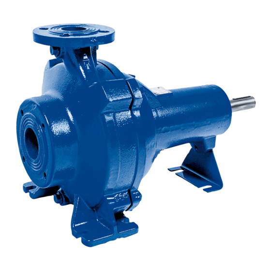
Figure V Pump with bare shaft at the drive end, sole plate and suction elbow 4.2 Designation Example: Sewatec F100-250GV Table 6: Designation key Code Description Sewatec Type series Impeller type... -
Page 16: Name Plate
4 Description of the Pump (Set) 4.3 Name plate Aktiengesellschaft Johann-Klein-Straße 9 67227 Frankenthal 2016 Sewatec D 300 - 400 P-No. 9971423078 / 000100 Q 306,44 l/s H 5,29 m n 983 1/min SNr. 24 15 26 Gew. 1090 kg Fig. -
Page 17: Design And Function
(9 and 10), which are supported by a bearing bracket (5) linked with the pump casing and/or casing cover. Sealing The pump is sealed by two bi-directional mechanical seals in tandem arrangement. A lubricant reservoir in-between the seals ensures cooling and lubrication of the mechanical seals. Sewatec 17 of 70... -
Page 18: Noise Characteristics
Some individual components weigh more than 25 kg. Observe the weights indicated.( or other applicable documents) Measured at a distance of 1 m from the pump outline (as per DIN 45635 Part 1 and 24) For nominal discharge nozzle diameter ≥ DN 100 Sewatec 18 of 70... -
Page 19: Installation At Site
Permissible deviation 0.2 mm/m. Use shims (2) for height compensation, if necessary. Always fit shims, if any, immediately to the left and right of the chemical anchors (4) between the baseplate/foundation frame and the foundation. Sewatec 19 of 70... -
Page 20: Piping
▷ Observe the permissible forces and moments at the pump nozzles. ▷ Take appropriate measures to compensate for thermal expansion of the piping. Mounting accessories of the respective manufacturer are required. Sewatec 20 of 70... - Page 21 050 - 250 115 050 - 251 115 065 - 215 140 065 - 216 140 065 - 217 140 065 - 250 140 K 065 - 252 140 065 - 253 140 080 - 215 180 Sewatec 21 of 70...
- Page 22 Where fluid has to be pumped out of a vessel under vacuum, installing a vacuum balance line is recommended. The following rules apply to vacuum balance lines: ▪ Minimum nominal line diameter 25 mm. ▪ The line extends above the highest permissible fluid level in the vessel. Sewatec 22 of 70...
-
Page 23: Auxiliary Connections
Risk of injuries by parts flying off and escaping fluid! ▷ Never use screw plugs for releasing pressure from the pump casing. ▷ Always use suitable venting devices (e.g. vent valve). The following auxiliary connections are available: 1M.1 1M.1 1M.2/6D Fig. 6: Auxiliary connections Sewatec 23 of 70... -
Page 24: Checking The Coupling Alignment
▷ Always check the coupling after the pump has been installed and connected to the piping. ▷ Also check the coupling of pump sets supplied with pump and motor mounted on the same baseplate. For vertical installation only Sewatec 24 of 70... -
Page 25: Checking The Belt Drive
Adjust the alignment, if required. (⇨ Section 7.5.8 Page 56) Fig. 8: Checking the pulley Re-fit the belt guard. alignment 5.7.2 Tensioning the belts CAUTION Lack of tension Insufficient power transmission! Wear resulting from excessive slip! ▷ Check the tension forces. Sewatec 25 of 70... -
Page 26: Aligning The Pump And Motor
▷ As soon as the work is complete, re-install and/or re-activate any safety-relevant and protective devices. 5.8 Aligning the pump and motor After having installed the pump set and connected the piping, check the coupling alignment and, if required, re-align the pump set (at the motor). Sewatec 26 of 70... -
Page 27: Checking The Lubricants
Risk of injury by rotating shafts! ▷ Always operate the pump set with a coupling guard. If the customer specifically requests not to include a coupling guard in KSB's delivery, then the operator must supply one! ▷ Observe all relevant regulations for selecting a coupling guard. -
Page 28: Electrical Connection
▷ Observe the technical specifications of the local energy supply companies. Check the available mains voltage against the data on the motor name plate. Select an appropriate start-up method. NOTE A motor protection device is recommended. Sewatec 28 of 70... -
Page 29: Checking The Direction Of Rotation
Vent the pump and suction line and prime both with the fluid to be handled. Fully open the shut-off valve in the suction line. Fully open all auxiliary connections (barrier fluid, flushing liquid, etc). Sewatec 29 of 70... -
Page 30: Protective Devices
Observe the technical literature of the sensor for fastening and electrical wiring. 692-02 (G 1/4) 692-01 692-02 (G 1/4) (G 1/4) 692-01 (G 1/4) Fig. 13: Positions of resistance thermometers 692-01 Temperature measuring device 692-02 Temperature measuring device No. 1 No. 2 Sewatec 30 of 70... -
Page 31: Commissioning/Start-Up/Shutdown
▷ See noise characteristics. (⇨ Section 4.6 Page 18) WARNING Abnormal noises, vibrations, temperatures or leakage Damage to the pump! Risk of personal injury! ▷ Switch off the pump (set) immediately. ▷ Eliminate the causes before returning the pump set to service. Sewatec 31 of 70... -
Page 32: Operating Limits
6.2.1 Maximum operating pressure, maximum test pressure CAUTION Permissible operating pressure exceeded Damage to connections and seals! ▷ Never exceed the operating pressure specified in the data sheet. Sewatec 32 of 70... - Page 33 150 - 401 200 - 315 200 - 316 200 - 317 200 - 318 200 - 330 200 - 400 K 200 - 402 250 - 400 250 - 401 300 - 400 300 - 401 Sewatec 33 of 70...
-
Page 34: Shutdown/Storage/Preservation
New pumps are supplied by our factory duly prepared for storage. ▪ Rotate the shaft of the pump by hand once a month. The pump (set) remains installed ✓ Sufficient fluid is supplied for the operation check run of the pump. Sewatec 34 of 70... -
Page 35: Returning To Service
Risk of personal injury from moving parts or escaping fluid! ▷ As soon as the work is complete, re-install and/or re-activate any safety-relevant and protective devices. NOTE On pumps/pump sets older than 5 years we recommend replacing all elastomer seals. Sewatec 35 of 70... -
Page 36: Servicing/Maintenance
NOTE All maintenance, service and installation work can be carried out by KSB Service or authorised workshops. For contact details please refer to the enclosed "Addresses" booklet or visit "www.ksb.com/contact" on the Internet. -
Page 37: Servicing/Inspection
▷ Collect and properly dispose of flushing fluid and any residues of the fluid handled. ▷ Wear safety clothing and a protective mask, if required. ▷ Observe all legal regulations on the disposal of fluids posing a health hazard. Sewatec 37 of 70... - Page 38 Explosion hazard! Fire hazard! Damage to the pump set! ▷ Regularly check the condition of the lubricant. 7.2.3.1 Lubricating the rolling element bearings The rolling element bearings of the pump sets are grease-packed and maintenance- free. Sewatec 38 of 70...
- Page 39 Fig. 16: Filling in the lubricant 7.2.3.3 Lubricant quantity Table 14: Lubricant quantity [l] Size Bearing bracket Lubricant quantity 050 - 215 050 - 216 050 - 250 050 - 251 065 - 215 065 - 216 065 - 217 Sewatec 39 of 70...
- Page 40 ▪ All non-doped and doped motor oils of classes SAE 10W to SAE 20W Alternative: NOTE Only use motor oil if there is no risk of the lubricant contaminating the fluid handled and if the motor oil can be disposed of properly. Sewatec 40 of 70...
-
Page 41: Drainage/Cleaning
▷ Drain the pump and release the pump pressure. (⇨ Section 7.3 Page 41) ▷ Close any auxiliary connections. ▷ Allow the pump set to cool down to ambient temperature. NOTE An impeller removal tool is required to remove the impeller. Sewatec 41 of 70... - Page 42 ▷ Close any auxiliary connections. ▷ Allow the pump set to cool down to ambient temperature. NOTE After the pump set has been dismantled, the suction casing should be cleaned with water. Suitable protective clothing is recommended. Sewatec 42 of 70...
- Page 43 Undo screwed connections 901.65, 550.65 and 920.65 and remove the motor from the motor plate. 7.4.4.1 Using taper clamping bushes ✓ Dismantling steps 1 to 3 have been completed. Loosen all screws. Sewatec 43 of 70...
- Page 44 330, shaft 210 and impeller 230 out of pump casing 101. Place the back pull-out unit in a safe and dry installation area and secure it against tipping over or rolling off. Sewatec 44 of 70...
- Page 45 Use a forcing screw to pull off impeller 230. Fig. 19: Removing the impeller NOTE The forcing screw is not included in the scope of supply. It can be ordered separately from KSB. Table 15: Forcing screws for pulling off the impeller Size Impeller type Forcing screw (ADS)
- Page 46 NOTE The impeller removal device is not included in the scope of supply. It can be ordered separately from KSB. 7.4.6.2.1 Using a special impeller removal device Fig. 21: Special fitting and removal tool Screw hexagon head bolt 1 into the shaft end to prevent any damage to the shaft thread.
- Page 47 Dismantling the motor-end mechanical seal ✓ The back pull-out unit and the impeller have been removed as described above. Remove locking ring 515 or circlip 932.03. Pull the rotating assembly of mechanical seal 433.01 off shaft 210. Sewatec 47 of 70...
- Page 48 7 Servicing/Maintenance 7.4.7.3 Removing the KSB cartridge mechanical seal Fig. 23: Removing the mechanical seal ✓ The back pull-out unit and the impeller have been removed as described above. Slide the puller over the shoulder of mechanical seal 433 and fasten it with the locking ring.
-
Page 49: Reassembling The Pump Set
6314 - 2 Z - C3 6314 - 2 Z - C3 Checking the alignment After assembly with the pump casing that has remained in the piping, check the coupling alignment. (⇨ Section 5.6 Page 24) Sewatec 49 of 70... - Page 50 ▪ To prevent any damage to the rubber bellows, place a thin foil (of approximately 0.1 to 0.3 mm thickness) around the free shaft stub. Slide the rotating assembly over the foil into its installation position. Then remove the foil. Sewatec 50 of 70...
- Page 51 330 as far as they will go. Guide the pump-end mechanical seal 433.02 onto shaft 210. When using a KSB cartridge mechanical seal, wet the outer O-rings with a soap solution prior to fitting them. Next, press seal 433 by hand into discharge cover 163 as far as it will go.
- Page 52 Slide impeller 230 onto the shaft end. Screw in impeller screw 914.10 and disc 550.23. Tighten them with a torque wrench. NOTE On shafts without a Helicoil thread insert secure the impeller screw with Loctite 243. Sewatec 52 of 70...
- Page 53 For bearing bracket sizes S01, S02 and S03 make sure that the tapered fit of impeller and shaft is undamaged and installed free from grease. For pump size Sewatec D 150-251 first screw screwed coupling 852 into the shaft. Sewatec...
- Page 54 The pump casing is not connected to the piping. 914.12 412.34 914.24 412.33 Fig. 31: Fitting the wear plate Equip wear plate 135 with two new O-rings 412.33 and 412.34. Use cardboard which easily dissolves in water. Sewatec 54 of 70...
- Page 55 Fasten the motor to motor plate 81-33 with bolts 901.65, discs 550.65 and nuts 920.65. Screw motor plate 81-33 including motor to motor bracket 890. Screw in height-adjusting elements 901.59 / 550.59. Mount motor bracket 890 on baseplate. Sewatec 55 of 70...
- Page 56 Table 20: Tightening torque for taper clamping bushes Bush Tightening torque Screws [Nm] Quantity Size 1004 / 1108 1/4" BSW 1310 / 1315 3/8" BSW 1210 / 1215 3/8" BSW 1610 / 1615 3/8" BSW Sewatec 56 of 70...
-
Page 57: Tightening Torques
Refer to the name plate for all data. Also specify the following data: ▪ Part number and description ▪ Quantity of spare parts ▪ Shipping address ▪ Mode of dispatch (freight, mail, express freight, air freight) Sewatec 57 of 70... - Page 58 ▪ Shaft protecting sleeve ▪ Lantern ring ✘ Packing cord (4 rings) 100 % ✘ Sealing elements (set) 150 % Keeping a stock of wear parts and replacement parts is recommended also during the warranty period. Sewatec 58 of 70...
-
Page 59: Trouble-Shooting
▷ For any work to remedy faults observe the relevant information in this manual or in the relevant accessory manufacturer's product literature. If problems occur that are not described in the following table, consultation with the KSB customer service is required. Pump delivers insufficient flow rate Motor is overloaded... - Page 60 Correct the distance according to general coupling distance arrangement drawing. ✘ - Operating voltage too low. Increase the voltage. Pump pressure must be released before attempting to remedy faults on parts which are subjected to pressure. Sewatec 60 of 70...
-
Page 61: Related Documents
0,018 0,028 3000 0,034 3000 0,030 0,044 3000 0,055 3000 0,034 0,07 10,5 3000 0,089 12,2 3000 0,048 0,11 3000 0,17 19,5 3000 0,068 0,21 22,5 3000 0,097 0,23 2700 0,16 0,34 2700 Without locking sleeve Sewatec 61 of 70... -
Page 62: General Assembly Drawing - Sewatec With Bearing Brackets S01, S02, S03, S04
360.02 901.01 903.01 550.01 411.01 515 / 932.03 932.20 411.22 412.04 412.15 411.46 903.46 433.01 903.22 Fig. 32: General assembly drawing – Sewatec with bearing brackets S01, S02, S03, S04, impeller type E Without locking sleeve Sewatec 62 of 70... - Page 63 Screw plug Impeller hub cap 904.01 Grub screw 321.01/.02 Radial ball bearing Impeller screw Bearing bracket 914.10/.12/.24 Hexagon socket head cap screw 360.02 Bearing cover 920.01/.17 411.01/.02/.03/.22/.46/.90 Joint ring 932.02/.03/.20 Circlip 412.04/.05/.15/.34 O-ring 940.01/.02 433.01/.02 Mechanical seal Sewatec 63 of 70...
-
Page 64: Exploded View: Sewatec With Bearing Brackets S01, S02, S03, S04
412.04 411.22 433.01 903.22 903.46 411.46 433.02 852* 550.23 914.10 Fig. 33: Exploded view of the pump; * For Sewatec D 150-251 a screwed coupling (852) is used in this position. 81-33 901.59 550.59 901.69 550.69 882.02 540.16 920.65 884.01 882.01... - Page 65 Bearing bracket 902.01 Stud 360.02 Bearing cover 903.01/.02/.03/.22/.46/.90 Screw plug 411.01/.02/.03/.22/.46/.90 Joint ring 914.10 Hexagon socket head cap screw 412.04/.15 O-ring 920.01/.65 433.01/.02 Mechanical seal 932.02/.20 Circlip Casing wear ring 940.02 Locking ring For Sewatec D150-251 only Sewatec 65 of 70...
-
Page 66: Eu Declaration Of Conformity
67227 Frankenthal (Germany) The manufacturer herewith declares that the product: Sewabloc, Sewatec KSB order number: ....................▪ is in conformity with the provisions of the following Directives as amended from time to time: – Pump (set): Machinery Directive 2006/42/EC The manufacturer also declares that ▪... -
Page 67: Certificate Of Decontamination
We confirm that the above data and information are correct and complete and that dispatch is effected in accordance with the relevant legal provisions....................................Place, date and signature Address Company stamp Required fields Sewatec 67 of 70... -
Page 68: Index
Shaft seal 16 Spare part Ordering spare parts 57 Spare parts stock 58 Impeller type 16 Storage 13 Installation Installation on a foundation 19 Installation at site 19 Intended use 8 Transport 12 Lubricant Quantity 39 Sewatec 68 of 70... - Page 70 KSB Aktiengesellschaft 67225 Frankenthal • Johann-Klein-Str. 9 • 67227 Frankenthal (Germany) Tel. +49 6233 86-0 • Fax +49 6233 86-3401 www.ksb.com...
Need help?
Do you have a question about the Sewatec and is the answer not in the manual?
Questions and answers