Table of Contents
Advertisement
Quick Links
Advertisement
Chapters
Table of Contents

Related Manuals for Getinge Maquet FLOW-i 4.2


Summary of Contents for Getinge Maquet FLOW-i 4.2
- Page 1 User's Manual FLOW-i 4.2 Anesthesia System...
- Page 3 Table of contents Table of contents Introduction Important System overview Startup and system checkout System functionality Breathing system AFGO (Additional Fresh Gas Outlet, Option) Membrane buttons Alarms and patient safety Ventilation modes System shutdown Routine cleaning and maintenance Technical specifications EMC Declaration Definitions Certificates...
- Page 4 Table of contents FLOW-i 4.2, User's Manual Infologic 1.67...
- Page 5 Introduction | 1 | 1 Introduction Table of contents Indications for use Intended use Using this manual FLOW-i 4.2, User's Manual...
- Page 6 | 1 | Introduction 1.1 Indications for use The indication for FLOW-i Anesthesia System is administering inhalation anesthesia while controlling the entire ventilation of patients with no ability to breathe, as well as in supporting patients with a limited ability to breathe. The system is intended for use on neonatal to adult patient populations.
- Page 7 Introduction | 1 | 1.3 Using this manual Important information is highlighted with Warning or Caution, where: This manual is divided into the following chapters: WARNING! Indicates critical information about a potential serious outcome to the • Chapters 1 and 2: Important information patient or the user.
- Page 8 | 1 | Introduction FLOW-i 4.2, User's Manual...
-
Page 9: Table Of Contents
Important | 2 | 2 Important Table of contents General information Connection Operation Installation and service Accessories and auxiliary equipment FLOW-i 4.2, User's Manual... -
Page 10: General Information
| 2 | Important 2.1 General information • If the mains power supply is interrupted, the internal battery will provide temporary • The following applies throughout this User's power to the system (approx. 90 minutes Manual: when fully charged). - 'FLOW-i', 'anesthesia system' and •... -
Page 11: Connection
Important | 2 | 2.2 Connection WARNING! To avoid the risk of electric shock, this equipment must only be • A full System checkout procedure must be connected to a supply mains with protective performed at least once a day. earth. -
Page 12: Operation
| 2 | Important 2.3 Operation • The equipotentiality terminal is designed for the connection of a potential equalization • The system shall always be used in conductor according to DIN 42 801 and combination with other vital signs IEC 60601-1. The function of the monitoring devices and/or professional equipotentiality terminal is to equalize human judgements of patient condition. -
Page 13: Installation And Service
Important | 2 | 2.4 Installation and service - Contacts of fuse holders that are accessible during replacement of the • Installation, service and maintenance of the fuse. system must be performed by personnel - Contacts of lamp holders that are trained and authorized by MAQUET. -
Page 14: Accessories And Auxiliary Equipment
| 2 | Important 2.5 Accessories and auxiliary • If there should be any deviation between equipment information shown on the system and that shown by auxiliary equipment, the • External equipment intended for connection parameters shown on the system shall be to signal input, signal output or other considered the primary source of connectors shall comply with relevant IEC... - Page 15 Important | 2 | • The use of O and Air gas outlets may, WARNINGS! depending on central gas supply pressure • The use of other accessories, and ventilation settings, affect ventilation transducers and cables other than those performance. specified by MAQUET may result in •...
- Page 16 | 2 | Important FLOW-i 4.2, User's Manual...
- Page 17 System overview | 3 | 3 System overview Table of contents System parts Control panel Patient monitor (option) Breathing system Vaporizer unit Emergency ventilation system External connections Explanation of symbols Ergonomical positioning 3.10 Storage and transportation 3.11 System models 3.12 Optional equipment FLOW-i 4.2, User's Manual...
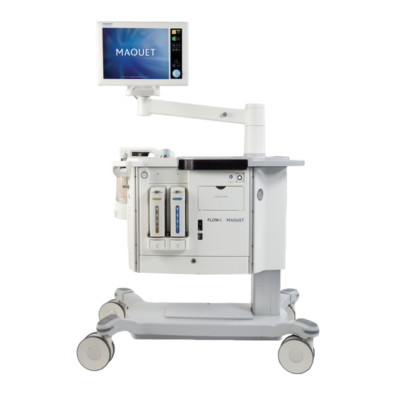
- Page 18 | 3 | System overview The anesthesia system is designed to enable the operator to work with the basic parts of the system in the most suitable way for each procedure. As the system is mounted on wheels, and the control panel is mounted on a rotatable arm, it can be easily moved into an ergonomically-suitable position.
- Page 19 System overview | 3 | 3.2 Control panel 01-01 13 00 The control panel includes: 1. Screen with active touch pads 2. Rotary knob 3. Membrane buttons FLOW-i 4.2, User's Manual...
- Page 20 | 3 | System overview 3.2.1 Areas of the screen The screen is divided up into a number of different areas: 1. Ventilation direct access settings 9. Tab area: 2. Gas direct access settings - Short trends 3. Activate additional settings/gas settings - Loops window - Volume Reflector Indicator...
- Page 21 System overview | 3 | The touch screen and rotary knob allow the Messages are displayed in the Alarm message operator to control the primary functions of area or System message area. The following the anesthesia system, where the patient's color scheme is adopted: condition is monitored through measured Color for alarms and system messages...
- Page 22 | 3 | System overview 3.2.2 Navigating the screen There are several ways of navigating the screen and setting values. Using the touch screen 1. Press the required touch pad. The touch pad becomes active, which is indicated by a blue highlight. 2.
- Page 23 System overview | 3 | Active screen Pressing any of the areas labelled with a number in the illustration, displays a window according to the table below. Screen area Dialog/window produced Gas settings/ Ventilation settings Multiple windows, see Chapter 5 MAC value Patient category, see Chapter 5, page 75.
- Page 24 | 3 | System overview 3.2.3 Touch pad settings 3.2.4 Membrane buttons A range bar is located at the bottom of all ventilation and gas touch pads, where a numeric value can be specified by the user. If the entered value deviates too far from the norm given the current ventilation mode and other parameter settings, the bar will change color according to the table below.
- Page 25 System overview | 3 | 3.3 Patient monitor (option) 3.4 Breathing system The system can be connected to a selection of different patient monitors. For full details, contact your local MAQUET representative. The patient monitor must comply with IEC 60601-1 ed. 3. During mains power failure, the backup battery in the anesthesia system will not power the patient monitor.
-
Page 26: Emergency Ventilation System
| 3 | System overview 3.5 Vaporizer unit 3.6 Emergency ventilation system mbar / cmH I/min Emergency ventilation I/min In case of a total power (i.e. mains power and battery) or system failure, this system will allow the patient to be manually ventilated. The emergency ventilation system comprises: 1. -
Page 27: External Connections
System overview | 3 | 3.7 External connections The following external connections exist on the system: 1. Power supply and fuses 2. Gas connections 3. Input/Output ports FLOW-i 4.2, User's Manual... - Page 28 | 3 | System overview 3.7.1 Power supply and fuses The patient monitor outlet and the auxiliary power outlets do not have a battery backup. 1. Auxiliary power outlets fuse 2A (option) 2. Auxiliary power outlets (option) 3. Auxiliary power outlets fuse 1A (option) 4.
- Page 29 System overview | 3 | 3.7.2 Gas connections WARNING! Restrictions apply to the use of auxiliary power outlets: • Outlets must not be used to power life support equipment unless the life support equipment itself is equipped with battery backup. •...
- Page 30 | 3 | System overview The intended use for the Auxiliary O outlet is 3.7.3 Input/Output ports to provide oxygen for patient therapy. The intended use for the Auxiliary AIR outlet is to provide drive gas for small ejector driven suction devices.
- Page 31 System overview | 3 | The network connection (LAN) port is for service use, and should only be used by personnel trained and authorized by MAQUET. External cables connected to the I/O ports must be secured using cable restrainers where available.
-
Page 32: Explanation Of Symbols
| 3 | System overview 3.8 Explanation of symbols Symbol Description Worn-out batteries must be 3.8.1 Labels recycled or disposed of properly in accordance with appropriate The following symbols are shown on the industrial and environmental standards. system: White drawing on a blue background. - Page 33 System overview | 3 | Symbol Description Symbol Description Medical device maximum weight absorber connected and (C20 with three drawers). C30 locked in position 365 kg and C40 are lighter, see technical specifications, page 266. absorber bypassed Red circle with a single red line over a black drawing.
- Page 34 | 3 | System overview Symbol Description Symbol Description Timer touch pad symbol, see Data communication Chapter 9, page 162 input/output ports Emergency ventilation Fuse Emergency ventilation Not for use with AFGO. Control panel connection Not for use with AFGO Emergency O flow is always delivered through the patient...
- Page 35 System overview | 3 | 3.8.2 Screen-displayed symbols Symbol Description Overlay loops The following symbols are shown on the screen: Numerical trends selected Symbol Description Standby mode Graphical trends selected Active alarm Activates a cursor in the trends display window, and allows for Multiple active alarms use of the rotary knob to scroll through values.
-
Page 36: Ergonomical Positioning
| 3 | System overview 3.9 Ergonomical positioning 3.9.1 Using the brake Once a suitable position has been found, the wheels should be locked into position. 1. Push the brake down to lock the wheel. • The C20 and C30 systems are on wheels 2. - Page 37 System overview | 3 | 3.9.2 Working position The flexibility of the system allows the operator many alternative working positions: Examples of working positions FLOW-i 4.2, User's Manual...
-
Page 38: Storage And Transportation
| 3 | System overview 3.10 Storage and transportation 3.10.2 During transport 3.10.1 Before transport • Move the system using the handles on the • If the system is to be moved to another main unit and not those on the control panel room or transported a longer distance, or patient monitor. - Page 39 System overview | 3 | 3.10.3 Storage • During storage keep the system connected to the mains power supply so that the batteries maintain a full charge. • If the system is disconnected from a power source, ensure the batteries are fully charged before storage to avoid deterioration of battery performance.
-
Page 40: System Models
| 3 | System overview 3.11 System models The anesthesia system is available in different models: • • • The following table shows the standard equipment for these different models (main components): • Working surface/writing table • Height adjustable • Ceiling pendant •... -
Page 41: Optional Equipment
System overview | 3 | 3.12 Optional equipment 3.12.1 Vaporizer holder Not all listed optional equipment may be The vaporizer holder provides easy access to available in your country, contact your local an additional vaporizer during surgical MAQUET representative for more information. procedures. - Page 42 | 3 | System overview 3.12.2 Universal bracket for C20 3.12.3 Manual breathing bag support arm The universal bracket for C20 is intended for The support arm provides a static and secure use with the FLOW-i C20 model only. It support for the manual breathing bag and provides additional space for mounting associated tubings.
- Page 43 System overview | 3 | 3.12.4 EVAC Restrictor 3.12.5 Cable support arm The EVAC restrictor acts to reduce the To organize and manage cables connecting pressure difference between high vacuum the patient to the patient monitor, a cable evacuation systems and the FLOW-i AGS support arm can be attached to any of the outlet.
- Page 44 | 3 | System overview 3.12.6 Top shelf CAUTIONS: • The maximum load of the top shelf is 20 The top shelf is attached to the display kg. Applies to all system models. column. Various types of equipment, e.g. • The size and placement of equipment parameter box and patient monitor, can be mounted on the top shelf must be...
- Page 45 System overview | 3 | 3.12.7 Vaporizer slot cover 3.12.8 Backup gas system The vaporizer slot cover is intended to protect The backup gas rack and backup gas cylinder the gas and electrical connections inside the holder are described in Chapter 10, page 204. vaporizer slot when no vaporizer is connected.
- Page 46 | 3 | System overview FLOW-i 4.2, User's Manual...
- Page 47 Startup and system checkout | 4 | 4 Startup and system checkout Table of contents System startup System checkout Leakage check Vaporizer check Understanding results Standby mode Start case Emergency ventilation FLOW-i 4.2, User's Manual...
-
Page 48: System Startup
| 4 | Startup and system checkout 4.1 System startup • Start the system by means of the Power button found directly above the Emergency ventilation system. FLOW-i 4.2, User's Manual... -
Page 49: System Checkout
Startup and system checkout | 4 | 4.2 System checkout To ensure correct system functionality, optimal performance and patient safety, the System checkout procedure must be performed as 01-01 13 00 follows: • Once a day, or before connecting the first patient within a running 24 hour period. - Page 50 | 4 | Startup and system checkout 4.2.1 Preparations 01-01 13 00 The first part of the System checkout An in-depth description of the different steps procedure ensures that the system is correctly is presented in the table on page 52. prepared for use.
- Page 51 Startup and system checkout | 4 | If an external Patient Gas Analyzer is used (not 4.2.2 Gas sampling leakage the one in FLOW-i), the sampling has to be The 'sampling leakage alarm' responds to switched off in order not to remove gas from amounts of leakage sufficient to interfere with the system.
- Page 52 | 4 | Startup and system checkout Preparatory steps Additional description Step 1 Check that the breathing circuit is correctly mounted and connected to the test plug (A). Step 2 Check the water trap and sampling line. Discard/empty any water present in the water trap. Step 3 Check that the absorber is correctly mounted and unsaturated.
- Page 53 Startup and system checkout | 4 | Preparatory steps Additional description Step 4 Check that the vaporizer(s) contains sufficient agent. Step 5 Check that the Anesthesia Gas Scavenging (AGS) flow indicator is above the dashed area. CAUTION: Ensure that the AGS is correctly connected.
- Page 54 | 4 | Startup and system checkout Preparatory steps Additional description Step 7 (only if backup cylinders are installed) Check that the Backup cylinders are opened. Close the cylinders after completing System checkout. The system checkout will not initiate if the system is not connected to the central gas supply.
- Page 55 Startup and system checkout | 4 | 4.2.3 Checks requiring user interaction 01-01 13 00 The second part of the System checkout B. Inspect the function of the inspiratory and procedure requires the user to perform a few expiratory unidirectional valves (some actions before proceeding to the next step: systems may be fitted with a patient cassette lid that needs to be opened to...
- Page 56 | 4 | Startup and system checkout 4.2.4 Automatic checks Components listed on the screen are individually tested. 'Passed' (in green text) or 'Failed' (in red text) is displayed after each test 01-01 13 00 depending on the outcome. 'Running' indicates the test currently being performed.
- Page 57 Startup and system checkout | 4 | If only the O backup gas cylinder is used, the 4.2.5 Finalization Air and/or N O backup gas cylinder pressure check can be disabled in Service and Settings 01-01 13 00 – Startup configuration, see Chapter 9, page 178.
- Page 58 | 4 | Startup and system checkout These checks can also be initiated in Standby 4.2.6 Bypassing System checkout mode via the Menu membrane button. In emergencies, the System checkout can be The results of each test in the System bypassed at any stage of the procedure.
-
Page 59: Leakage Check
Startup and system checkout | 4 | 4.3 Leakage check The automatic check sequence includes automatic and manual breathing circuit Performs a Leakage check of the manual and leakage checks. automatic breathing circuits. It shall be performed after each change of tubings, 01-01 13 00 breathing bags or filters. -
Page 60: Vaporizer Check
| 4 | Startup and system checkout 4.4 Vaporizer check 01-01 13 00 Performs a leakage check of the manual and automatic breathing circuits and a check of vaporizer functionality. It shall be performed after a vaporizer has been connected to the system. -
Page 61: Understanding Results
Startup and system checkout | 4 | 4.5 Understanding results Patient cases should not be started if only Leakage or Vaporizer checks have been performed since system startup or during the 01-01 13 00 last 24 hours period. Press the 'Results' touch pad to display a window describing the system checkout results in more detail. -
Page 62: Standby Mode
| 4 | Startup and system checkout 4.6 Standby mode If the System checkout was bypassed, or if the System checkout failed, a corresponding system message will be displayed in the message area. 01-01 13 00 When a patient case is started using AUTO ventilation or a switch is made during Run mode to AUTO ventilation, the preset gas and ventilation settings are activated. -
Page 63: Start Case
Startup and system checkout | 4 | 4.7 Start case 4.7.1 Compliance compensation Once a successful system checkout has been Part of the volume of each inspiration will not performed, the system is ready to start a reach the patient because of gas compression patient case. -
Page 64: Emergency Ventilation
| 4 | Startup and system checkout 4.8 Emergency ventilation If the emergency ventilation is activated, either during a patient case or when testing the 4.8.1 Manual check of Emergency system, the emergency ventilation APL valve ventilation system must be set to minimum before resuming normal ventilation (AUTO or MAN) or starting To test its operation, perform the following: a new patient case. - Page 65 System functionality | 5 | 5 System functionality Table of contents FLOW-i Anesthesia system Patient settings Fresh gas flow settings Ventilation settings Measured values Waveform area Inspiratory and expiratory hold Miscellaneous FLOW-i 4.2, User's Manual...
-
Page 66: Flow-I Anesthesia System
| 5 | System functionality 5.1 FLOW-i Anesthesia system 5.1.1 Tidal volume delivery The FLOW-i is a software controlled circle The tidal volume delivered to the patient system for anesthesia. It features several comes from two sources: the fresh gas flow components distinguishing it from other and exhaled gas in the volume reflector anesthesia systems;... - Page 67 System functionality | 5 | 5.1.2 Low flow anesthesia The use of oxygen as the drive gas in the volume reflector diminishes the risk for hypoxia should a leakage occur during low, or minimal flow anesthesia. However, should a leakage occur (the source of which is either known of unknown), then the volume reflector always ensures ventilation (it will never collapse like...
- Page 68 | 5 | System functionality 5.1.3 Safety functions in FLOW-i to avoid Safety flush potential hypoxia If the inspiratory oxygen concentration falls To prevent the oxygen concentration in the even lower, possibly due to gas delivery breathing circuit from becoming too low and malfunction, then the system performs a safety potentially causing hypoxia, the system has flush replacing the entire breathing circuit...
- Page 69 System functionality | 5 | Inspiratory oxygen concentration and alarm limits The illustration opposite shows how the settings for the 'FiO : Low' alarm affect the activation thresholds for O Guard and the Safety Flush. At lower alarm settings, the respective thresholds for O Guard and Safety Flush decrease accordingly to avoid...
- Page 70 | 5 | System functionality 5.1.4 Manual ventilation The fresh gas flow is constant during both inspiration and expiration when manual breathing mode is selected. Inspiration Expired gas is, together with new fresh gas from the gas modules, re-administered to the patient by compression of the manual breathing bag.
- Page 71 System functionality | 5 | Expiration Exhaled gas enters the volume reflector. Fresh gas is added to the circle system from the gas modules. Due to the counter pressure in the inspiratory channel caused by flow from the patient, fresh gas delivered during the expiration phase will fill the CO absorber.
- Page 72 | 5 | System functionality 5.1.5 Automatic ventilation The fresh gas delivery is designed to be cost effective with regards to agent consumption. The fresh gas flow is thus limited to the set minute volume, i.e. the delivered fresh gas can never exceed the set minute volume.
- Page 73 System functionality | 5 | Expiration Exhaled gas enters the volume reflector. Reflector gas is pushed back and evacuated through the PEEP valve. Due to the counter pressure in the inspiratory channel caused by flow from the patient, fresh gas delivered during the expiration phase will fill the CO absorber.
-
Page 74: Patient Settings
| 5 | System functionality 5.2 Patient settings Press each data field and use the rotary knob to set and confirm the patient data value. The patient data (1-5) is used to determine 01-01 13 00 allowable ventilatory setting ranges, relative and recommended ventilatory values. - Page 75 System functionality | 5 | 5.2.1 Patient category Changing the patient category affects the following: The selected patient category is either 'Infant' or 'Adult'. This determines the allowable • Alarm ranges and defaults setting ranges for ventilatory parameters and • Circuit compliance compensation patient data.
- Page 76 | 5 | System functionality 5.2.2 Patient Age 5.2.6 Predicted body weight This field is never blank. If no information is If all patient details have been filled in, PBW entered, the default value will be used. will be displayed. In some cases, it will be the same as the actual body weight, while in Select 'Age' in the patient settings menu and others the PBW may be either higher or lower...
- Page 77 System functionality | 5 | The PBW value displayed here forms the basis Height < 135 Height > 135 Gender - for all values for ventilatory parameters female recommended in this window. Weight < 30 kg Actual body PBW based on The estimated PBW may be displayed weight used for a combination...
- Page 78 | 5 | System functionality 5.2.7 Recommended values The values recommended here for Tidal volume, Resp. rate and Minute volume are based on the patient category selected and the patient data entered. Values that are out of range for the patient category are highlighted in yellow.
-
Page 79: Fresh Gas Flow Settings
System functionality | 5 | 5.3 Fresh gas flow settings 01-01 13 00 The fresh gas supply is set using the following touch buttons: 1. Gas mix 2. Fresh gas flow 3. O concentration 4. Agent concentration FLOW-i 4.2, User's Manual... - Page 80 | 5 | System functionality 5.3.1 Selection of gas mixture 5.3.2 Setting fresh gas flow 01-01 13 00 01-01 13 00 There are two settings: Total fresh gas flow in liters/minute. • /Air (oxygen/air) The minimum O flow is 200 ml/min. The •...
- Page 81 System functionality | 5 | 5.3.3 Setting O concentration 5.3.4 Setting anesthesia agent concentration 01-01 13 00 01-01 13 00 Percentage oxygen set in the fresh gas Sets the anesthesia agent concentration for mixture. The range of the fresh gas the selected vaporizer.
- Page 82 | 5 | System functionality 5.3.5 Selecting active vaporizer Selecting an active vaporizer is necessary if: • The vaporizer is connected into the non-selected slot. • There is a need to change the active vaporizer when there are two vaporizers connected to the system.
-
Page 83: Ventilation Settings
System functionality | 5 | 5.4 Ventilation settings 3. To select a vaporizer, press the required vaporizer type and confirm by pressing The system can be run using manual (MAN) Accept. This activates the vaporizer. The or automatic (AUTO) ventilation. Ventilation agent name is shown on the Vaporizer modes available for automatic ventilation setting touch pad. - Page 84 | 5 | System functionality 5.4.1 MAN/AUTO ventilation switch Using manual ventilation Manual ventilation is performed using the manual breathing bag to administer breaths, and the APL valve to regulate the pressure limit. For details on the APL valve, see page 122.
- Page 85 System functionality | 5 | Using automatic ventilation Automatic ventilation is performed using the built-in ventilator, where the ventilation mode initially selected will depend on the system's startup configuration, see Chapter 9. For a detailed description of each automatic ventilation mode, see Chapter 11. The required ventilation settings can be pre-set before switching to automatic ventilation.
- Page 86 | 5 | System functionality 5.4.2 Parameter settings 01-01 13 00 The ventilation parameter settings are Due to interdependencies between parameter controlled using the following touch pads on settings, certain setting combinations are not the screen: possible, particularly settings relating to breathing cycle phases (Ti, Tinsp rise, Tpause 1.
- Page 87 System functionality | 5 | 5.4.3 Selection of automatic ventilation If AFGO is installed on the system then manual mode and AFGO ventilation appear as selectable options to the left of this window. These options can be preset in preparation for switching to manual breathing mode using the 01-01 13 00 MAN/AUTO switch, see Chapter 7, page 151.
- Page 88 | 5 | System functionality When selecting the required ventilation mode, Direct access ventilation settings are always the set ventilation mode parameter window accessible at the bottom right of the control appears: panel. Additional settings can be viewed anytime by pressing the triangular 'Additional settings' 01-01 13 00 touchpad located above the direct settings...
- Page 89 System functionality | 5 | Pressure Control Ventilation mode parameter window Additional settings window 1. PEEP 1. I:E or Ti (inspiration time) 2. Respiratory Rate 2. T insp. rise 3. PC above PEEP 3. Trigger 4. I:E or Ti (inspiration time) 4.
- Page 90 | 5 | System functionality Volume Control Ventilation mode parameter window Additional settings window 1. PEEP 1. Trigger 2. Respiratory Rate 2. I:E or Ti (inspiration time) 3. Tidal/Minute volume 3. T pause 4. I:E or Ti (inspiration time) 4. T insp. rise 5.
- Page 91 System functionality | 5 | PRVC Ventilation mode parameter window Additional settings window 1. PEEP 1. Trigger 2. Respiratory Rate 2. I:E or Ti (inspiration time) 3. Tidal/Minute volume 3. T insp. rise 4. I:E or Ti (inspiration time) 4. Estimated parameters 5.
- Page 92 | 5 | System functionality Pressure Support Ventilation mode parameter window Additional settings window 1. PEEP 1. PS above PEEP 2. PS above PEEP 2. PC above PEEP 3. T insp. rise 3. Trigger 4. Trigger 4. Insp. cycle off 5.
- Page 93 System functionality | 5 | SIMV (PC) + PS Ventilation mode parameter window Additional settings window 1. PEEP 1. PS above PEEP 2. SIMV rate 2. Trigger 3. PC above PEEP 3. Insp. cycle off 4. I:E or Ti (inspiration time) 4.
- Page 94 | 5 | System functionality SIMV (VC) + PS Ventilation mode parameter window Additional settings window 1. PEEP 1. PS above PEEP 2. SIMV rate 2. Trigger 3. Tidal/Minute volume 3. Insp. cycle off 4. I:E or Ti (inspiration time) 4.
- Page 95 System functionality | 5 | 5.4.4 Setting direct access parameters 01-01 13 00 The following direct access parameters can be set for the selected ventilation mode: Ventilation Tidal/Minute PC above PS above Respiratory Backup SIMV rate PEEP mode volume PEEP PEEP Rate PRVC...
- Page 96 | 5 | System functionality Tidal/Minute volume Pressure control above PEEP 01-01 13 00 01-01 13 00 Sets the tidal/minute volume. Sets the pressure level above PEEP . When the set inspiration pressure above PEEP is Different setting intervals apply for adult and reached, the system generates a pressure infant patient categories, see table below.
- Page 97 System functionality | 5 | Pressure support above PEEP Backup respiratory rate 01-01 13 00 01-01 13 00 Sets the frequency of pressure controlled PS above PEEP is the set inspiratory pressure support level for triggered breaths in pressure administered breaths, i.e. backup rate, should support.
- Page 98 | 5 | System functionality SIMV rate PEEP 01-01 13 00 01-01 13 00 Rate of controlled mandatory breaths (b/min). Sets the Positive End Expiratory Pressure. Active only in SIMV modes. The system allows PEEP settings within the range 0 to 50 cmH FLOW-i 4.2, User's Manual...
- Page 99 System functionality | 5 | 5.4.5 Setting additional parameters The following additional parameters can be set for the selected ventilation mode: Breath Ventilation T insp. Insp. Trigger I:E/Ti T pause above above cycle mode rise cycle off PEEP PEEP time PRVC SIMV (PC) + PS...
- Page 100 | 5 | System functionality Setting inspiration time ventilation. A decrease of the inspiratory flow to a preset level causes the system to switch The following parameters can be set to control to expiration. This preset level is measured as inspiration time: a percentage of the maximum flow during inspiration.
- Page 101 System functionality | 5 | Setting trigger Flow triggering can be set in the range 1 to 10 (green and red area on the bar). This roughly The following parameter can be set to control corresponds to the effort that the patient has the trigger.
- Page 102 | 5 | System functionality Weak patient effort Stronger patient effort 1. At a Trigger sensitivity level above zero (0), the system senses deviations in the 1. At a Trigger sensitivity level below zero flow through the PEEP valve caused by (0), the system senses negative pressures inspiratory efforts of the patient.
- Page 103 System functionality | 5 | Monitoring patient effort Administered breaths triggered by patient effort are highlighted in the waveform display area: 01-01 13 00 A purple color is superimposed on the inspiratory phase of either the pressure curve (pressure triggering) or the flow curve (flow triggering).
- Page 104 | 5 | System functionality 5.5 Measured values The following ventilation values can be displayed in two pages of information: 5.5.1 Ventilation measurements Flow Volume Ppeak PEEP (cmH 2 0) (cmH 2 0) • RR (mandatory) • MVe (mandatory) • •...
- Page 105 System functionality | 5 | Page 1 Four values can be displayed in a large font, and four values in a smaller font. Large font values have the following extra information displayed on the panel screen: • Associated upper and lower alarm limits •...
- Page 106 | 5 | System functionality 5.5.2 Gas measurements 5.5.3 Gas supply pressure Air N 01-01 13 00 4.3 3.9 4.5 4.8 3.5 4.3 O (%) The current gas supply pressure (mains supply and backup gas supply) can be displayed in the upper left area of the control panel.
- Page 107 System functionality | 5 | 5.6 Waveform area 01-01 13 00 The waveform area is customizable, allowing There are two methods of activating and for different arrangements of displayed displaying any one of these tabs: information. • Startup Configuration. Settings affect the In addition to the real-time waveforms, any number and type of tabs shown at the start one of the following can be shown...
- Page 108 | 5 | System functionality The Pressure waveform is mandatory and Waveform tab always displayed at the top of the waveform display area. Displayed gas waveforms have a four second delay, and are thus not synchronized with the pressure, flow or volume waveforms. The following information can be displayed as waveforms: •...
- Page 109 System functionality | 5 | Short trends tab Ppeak (cmH2O) V (l/min) etCO2 -30 min 0 min The short trend tab depicts waveform data going back 10, 30 or 60 minutes. The type and number of these shortened waveforms match the screen layout of the displayed real time waveforms.
- Page 110 | 5 | System functionality By pressing the overlay loops touch pad (4), Loops the two latest loops are displayed together with the current loop. Pressing both touch pads (3+4) will display the reference loop and the two latest loops together with the real-time loop.
- Page 111 System functionality | 5 | Volume reflector VRI (Volume Reflector Indicator) The VRI is a graphic representation of the ratio of reflector gas (white) to exhaled gas (gray) in the volume reflector. The diffusion point, i.e. border between white and gray, moves back and forth with each breathing cycle.
- Page 112 | 5 | System functionality VR Balance (Volume Reflector Balance) RBF (Rebreathing Fraction) This metric describes the net flow of gas from This metric describes how much of the the volume reflector into the AGS system. It exhaled gas is being re-used during each is measured during the last complete breath successive breath (during inspiration).
- Page 113 System functionality | 5 | The Gas pressure tab offers a clear visual representation of the mains gas supply and the backup gas supply. Amount of gas remaining in connected backup cylinders is approximated and displayed in the right section. To get the actual cylinder pressure, press the 'Menu' membrane button and access the 'system info' sub-category.
- Page 114 | 5 | System functionality 5.7 Inspiratory and expiratory hold Measurements start at the end of expiration/inspiration irrespective of the time Using the inspiratory and expiratory hold when the touch pad was pressed down. If function enables certain lung characteristics 'Insp.
- Page 115 System functionality | 5 | The 'Insp Exp hold' dialog can be accessed The 'Insp. Exp. Hold' dialog has two active by either of the following: touch pads: 1. Press the 'Calculate static measurements' touch pad, located on page three in the ventilation measurements area.
- Page 116 | 5 | System functionality Inspiratory hold Expiratory hold ≥ 5s ≥ 5s Typical appearance of waveforms during Typical appearance of waveforms during inspiration hold (volume control). Note the lack expiration hold (volume control). Note the lack of flow when the feature is active (gray). of flow when the feature is active (gray).
- Page 117 System functionality | 5 | 5.8 Miscellaneous 5.8.2 Power and battery status 5.8.1 Date and time The displayed date and time at the top of the 01-01 13 00 touch screen is set during system installation. 01-01 13 00 The power and battery status is shown at the top-left on the control panel.
- Page 118 | 5 | System functionality 5.8.3 Timer 01-01 13 00 01:25:13 See Chapter 9 'Membrane buttons' on how to operate the timer functions. FLOW-i 4.2, User's Manual...
- Page 119 Breathing system | 6 | 6 Breathing system Table of contents Breathing system Patient cassette flush MAN/AUTO ventilation switch APL valve Volume reflector Anesthetic gas scavenging (AGS) Patient tubing Manual breathing bag 6.10 Water trap and sampling line 6.11 absorber 6.12 Auxiliary O and suction module (option)
-
Page 120: Breathing System
| 6 | Breathing system 6.1 Breathing system 6.2 Patient cassette The breathing system comprises the following: 1. Patient cassette 2. O flush The patient cassette is the center of gas flow 3. MAN/AUTO ventilation switch in the system. 4. APL valve 5. -
Page 121: Man/Auto Ventilation Switch
Breathing system | 6 | 6.3 O flush 6.4 MAN/AUTO ventilation switch See page 84 for a detailed description. The O flush is used to manually supply the breathing system with an additional gas flow from the O gas supply. For details refer to section Fresh gas flow on page 273. -
Page 122: Apl Valve
| 6 | Breathing system 6.5 APL valve 6.6 Volume reflector Adjustable Pressure Limit valve. The APL valve is mechanically regulated by The re-breathing function in FLOW-i is means of the APL knob, i.e it is not regulated supported by the volume reflector. It functions using any of the control panel touch pads. -
Page 123: Anesthetic Gas Scavenging (Ags)
Breathing system | 6 | 6.7 Anesthetic gas scavenging (AGS) CAUTION: If the central scavenging system is inactive, the gases and agents used for When the AGS is connected to the rear of the anesthesia will be emitted into the operation system, the flowmeter on the front indicates room. -
Page 124: Patient Tubing
| 6 | Breathing system 6.8 Patient tubing 6.9 Manual breathing bag Maquet recommends using patient tubings measuring from 1.2 to 3 meters in length. It is recommended only to use original tubes from MAQUET. Soft tubing or tubing with high internal resistance may negatively effect the performance of the system. - Page 125 Breathing system | 6 | 6.10 Water trap and sampling line 6.11 CO absorber The water trap protects the internal gas analyzer from humidity, bacterial contamination, etc. It consists of a filter housing and a water container. For a detailed description, see page 144. The pre-packed CO absorber contains 24 fl oz (700 ml) of absorbent (soda lime).
- Page 126 | 6 | Breathing system Unlocked Bypassed (not applicable to all systems) In this position, the patient cassette seals the In this position, the patient cassette seals the gas flow and bypasses the absorber. gas flow and bypasses the absorber. Turn the locking switch counter-clockwise to Turn the locking switch counter-clockwise to return the absorber into the breathing system.
- Page 127 Breathing system | 6 | Replacement of absorber Being alkaline in nature, soda lime should not be allowed to come into contact with sensitive During use, a pink (white-to-pink grade) or skin, particularly with the eyes or mucous violet (white-to-violet grade) color will develop membranes.
- Page 128 | 6 | Breathing system Storage Containers holding unused absorbers should be stored in a clean, dry environment, and at temperatures between 0°C (32 F) and 35°C C). Storage at higher temperatures can result in reduced efficiency and service life due to moisture loss.
-
Page 129: Auxiliary O 2 And Suction Module (Option)
Breathing system | 6 | 6.12 Auxiliary O and suction module With the tube adapter attached, the flowmeter (option) outlet can be connected to 4, 6 and 8 mm tubings (0.16 in., 0.24 in. and 32 in. resp.) Testing the Flowmeter Test the Flowmeter unit before use, e.g. - Page 130 | 6 | Breathing system 1. Attach and secure the angular adapter (A) Bubble humidifier (option) to the flowmeter unit by means of the cap To protect patient lung tissue and airways from nut and tighten by hand. The angular drying out, e.g.
- Page 131 Breathing system | 6 | Suction unit The length of tubings connecting the septic fluid jar with the unit shall not exceed 1 m. The The intended use for the Suction unit is to tube material should be rigid enough to extract body fluids from the stomach and prevent occlusion.
- Page 132 | 6 | Breathing system Testing the Suction unit WARNING! The Suction unit must only be used by personnel who have received The Suction unit shall be tested before use, adequate instructions of use. i.e. during the System checkout. Follow the steps outlined below: CAUTIONS: 1.
-
Page 133: Emergency Ventilation System
Breathing system | 6 | 6.13 Emergency ventilation system When settings have been made, ventilate the patient using the manual breathing bag. In case of a total power (mains power and battery) or other electronic failures, the built-in If the emergency ventilation is activated, either emergency ventilation system can be used. -
Page 134: Vaporizers
| 6 | Breathing system 6.14 Vaporizers Just above the vaporizer, an LED lamp shows the status of the vaporizer or the vaporizer slot (see table). LED color Vaporizer status Green The selected vaporizer has passed the System checkout or Vaporizer check, and is ready to deliver agent. - Page 135 Breathing system | 6 | 6.14.1 Connecting a vaporizer Connecting a vaporizer in Standby mode Vaporizers can be connected during Standby Insert the vaporizer into the vaporizer slot and and Run mode. push into place until a click is heard. Before inserting the vaporizer in the vaporizer A prompt window appears: 'A vaporizer check slot, a visual check of the exterior and the...
- Page 136 | 6 | Breathing system Connecting a vaporizer during Run mode Insert the vaporizer into the vaporizer slot and push into place until a click is heard. The vaporizer check cannot be performed during Run mode. A 'Vaporizer check bypassed' message will be displayed on the screen, and an entry is made in the event log.
- Page 137 Breathing system | 6 | 6.14.2 Selecting active vaporizer 3. To select a vaporizer, press the required vaporizer type and confirm by pressing Selecting an active vaporizer is necessary if: Accept. This activates the vaporizer. The • The vaporizer is connected into the agent name is shown on the Vaporizer non-selected slot.
- Page 138 | 6 | Breathing system 6.14.3 Re-filling a vaporizer Filling adapters are either fastened onto the opening of the bottle by the manufacturer The liquid level can be seen in the monitor (SAFE-FIL , Quik-fil®), or are attached onto tube on the front of the vaporizer, or in the the bottle by the user before refilling (MAQUET Select vaporizer window.
- Page 139 Breathing system | 6 | Re-filling while connected 2. Position the adapter onto the vaporizer. Again, the specific adapter will only match There is no need to turn off the vaporizer. the correct vaporizer. Press the bottle Perform the following: downwards so that the agent liquid flows into the vaporizer.
- Page 140 | 6 | Breathing system Re-filling when disconnected The procedure is identical to when the vaporizer is connected to the system. Refer to hospital routines regarding handling anesthetic agents and refilling processes. FLOW-i 4.2, User's Manual...
- Page 141 Breathing system | 6 | 6.14.4 Disconnecting a vaporizer When the system message appears in the message area, lift the locking handle upwards Before disconnecting a vaporizer, it needs to and remove the vaporizer. be deactivated. This is done either by setting the vaporizer to non-active in the Select vaporizer window, or by using the rotary knob to deactivate the vaporizer.
- Page 142 | 6 | Breathing system 6.14.5 Emptying a vaporizer 6.14.6 Vacant vaporizer slots MAQUET recommends that the vaporizers are When not currently occupied by a vaporizer, emptied before long distance transportation a protective cover can be used to cover the or long term storage.
-
Page 143: Gas Analyzer
Breathing system | 6 | 6.15 Gas analyzer If an external gas analyzer is used which does not return it's sample flow into the breathing Located inside the main unit, the gas analyzer circuit, the fresh gas flow and tidal volume provides a DIR (dispersive infrared) should be set to compensate for the lost measurement of respiratory and anesthetic... - Page 144 | 6 | Breathing system 6.15.2 Water trap and sampling line WARNINGS! • If a broken water trap has been used The water trap protects the internal gas during operation, the gas analyzer might analyzer from humidity, bacterial be contaminated and damaged. If this is contamination, etc.
- Page 145 Breathing system | 6 | 6.15.3 MAC values is a constant related to the delivered Agent anesthetic agent: rel,barcomp The presented MAC (MAC ) is relative to MAC , and pressure compensated to Agent and N account for fluctuations in ambient pressure. Isoflurane (Forene) 1.15% It is calculated as follows:...
-
Page 146: Lift (C30 Model Only)
| 6 | Breathing system 6.16 Lift (C30 model only) 6.15.4 Warm-up During startup, the gas analyzer passes With the mains power connected, the lift through an initialization and warm-up period, function is operated by means of the Up and where the etCO2, O2, and agent values are Down buttons located to the right of the displayed as '***' for 60 seconds before ISO... -
Page 147: Ceiling Pendant (C40 Model Only)
Breathing system | 6 | 6.17 Ceiling pendant (C40 model only) The FLOW-i C40 system can be attached onto a variety of ceiling pendant systems. Contact your local MAQUET supplier for more information. Only personnel trained and authorized by MAQUET may install the C40 model. The maximum lift capacity of the ceiling pendant may limit the number of accessory equipment that can be mounted onto the C40... -
Page 148: Breathing System
| 6 | Breathing system 6.17.1 Docking and undocking The C40 system must always stand on the floor when it is being docked or undocked onto or from the ceiling pendant. The C40 system is intended for transport inside the operation room only when undocked from the ceiling pendant. - Page 149 AFGO (Additional Fresh Gas Outlet, Option) | 7 | 7 AFGO (Additional Fresh Gas Outlet, Option) Table of contents General Preparations Manage AFGO settings Further information about the use of AFGO FLOW-i 4.2, User's Manual...
-
Page 150: General
| 7 | AFGO (Additional Fresh Gas Outlet, Option) 7.1 General Pre-selecting or activating AFGO in the ventilation dialog window requires user Additional Fresh Gas Outlet (AFGO) is an confirmation. On selecting the AFGO option to the anesthesia system that allows touchpad, a pop-up dialog appears asking the use of an external partial rebreathing system, user to confirm the action. -
Page 151: Preparations
AFGO (Additional Fresh Gas Outlet, Option) | 7 | 7.2 Preparations 7.3 Manage AFGO settings Before using the AFGO outlet, make sure that normal system checkout procedures have been performed and the following 01-01 13 00 requirements are fulfilled: When the AFGO function is installed on the system, AFGO ventilation is available for selection in the dialog window produced by pressing the ventilation mode area. - Page 152 | 7 | AFGO (Additional Fresh Gas Outlet, Option) 7.3.1 Preset and activate AFGO in Standby 7.3.2 Activate AUTO from AFGO • Select 'Additional Fresh Gas Outlet (AFGO)' Parameters for Automatic Ventilation can be and confirm selection in the dialog preset during AFGO via the ventilation dialog window.
-
Page 153: Further Information About The Use Of Afgo
AFGO (Additional Fresh Gas Outlet, Option) | 7 | 7.4 Further information about the use 7.3.3 Activate AFGO from AUTO of AFGO • Ensure that 'Additional Fresh Gas Outlet (AFGO)' is pre-set in the ventilation mode Gas scales and waveforms for gases are touch pad. - Page 154 | 7 | AFGO (Additional Fresh Gas Outlet, Option) FLOW-i 4.2, User's Manual...
- Page 155 Membrane buttons | 8 | 8 Membrane buttons Table of contents Overview Audio pause Alarm profile Start/End case Save screen Trends Timer Home Screen layout 8.10 Menu FLOW-i 4.2, User's Manual...
- Page 156 | 8 | Membrane buttons 8.1 Overview 8.2 Audio pause The membrane buttons are used to quickly The Audio pause membrane button has the access information in the system and/or action following applications: certain specific functions. • Mutes active alarm sound signals for two minutes •...
- Page 157 Membrane buttons | 8 | 8.3 Alarm profile 8.4 Start/End case Shows all applicable alarms for the currently 8.4.1 Start case selected ventilation mode (MAN or AUTO) Starts a new patient case and activates the along with their set upper and lower limits. preset gas and ventilation settings depending on the setting of the AUTO/MAN ventilation switch.
- Page 158 | 8 | Membrane buttons 8.5 Save screen Go to Standby Return to Standby mode. Saves a copy of the screen to a USB memory device. All settings (gas, ventilation and alarm limits) are unaltered, apart from agent concentration, A USB memory device must first be inserted which is set to OFF.
- Page 159 Membrane buttons | 8 | 8.6 Trends Pressing Trends opens a new window displaying the latest trend data in either numerical or graphical form. Switch between the graphic and numeric trends window by pressing the graphic (left) or numerical (right) touch pad button located at the lower left in the trends window.
- Page 160 | 8 | Membrane buttons 8.6.1 Numerical display 8.6.2 Scroll bars Scroll bars are used to navigate through listed information or available values. Select the 12:58 scroll bar, positioned to the right of the Agent window, by pressing it on the touch screen. Time 12:58 Press the up and down arrows on the scroll...
- Page 161 Membrane buttons | 8 | 8.6.3 Graphical display time and measured value corresponding to the current position of the line are displayed in the top left, and left part of the display window respectively. 12:58 06:58 07:58 08:58 09:58 10:58 11:58 12:58 At the top of the window, log events are...
- Page 162 | 8 | Membrane buttons 8.7 Timer 8.8 Home The Timer is controlled by two membrane Cancels current window settings, closes the buttons - Start/Stop and Reset. window and returns to the main screen. Press Start/Stop once to start a timer visible Pressing Home will unlock a control panel at the top right of the screen.
- Page 163 Membrane buttons | 8 | 8.9 Screen layout 8.9.1 Waveforms and scales Allows the user to configure the screen layout and brightness. Layout options include display loops and rotameter, waveform combinations and the scaling of these. Waveform scaling can be set to manual or automatic.
- Page 164 | 8 | Membrane buttons 8.10 Menu 8.9.2 Screen brightness The backlight on the control panel can be Displays the main menu. adjusted, depending on the surrounding lighting, to provide the optimal screen 01-01 13 00 readability. 100 % 75 % 50 % The menu gives access to the following functions:...
- Page 165 Membrane buttons | 8 | 8.10.1 Patient settings Menu - Patient settings Used to select patient settings. For a complete description, see section Patient settings on page 74. FLOW-i 4.2, User's Manual...
- Page 166 | 8 | Membrane buttons 8.10.2 System checkout Menu - System checkout Result Brings up a detailed summary of the last System check, including leakage info and circuit compliance calculations, and the result of the System check before that. Full check 01-01 13 00 Starts a full system checkout.
- Page 167 Membrane buttons | 8 | Menu - System checkout Vaporizer check 01-01 13 00 Performs a Leakage check and a Vaporizer check. The additional Vaporizer check ensures functionality of the vaporizer and that no agent escapes into the operating room. 8.10.3 Status Menu - Status System info...
- Page 168 | 8 | Membrane buttons 8.10.4 Logs Menu - Logs Alarms Displays the alarm log, with the most recent at the top of the list. All logs Displays a list of all logs - System checkout, Alarms, Ventilation settings and Events - in chronological order with the most recent at the top of the list.
- Page 169 Membrane buttons | 8 | 8.10.5 Save & delete data Menu - Save & delete data Save trends & logs to USB Data can be stored onto a USB memory device for storage or further analysis. Delete trends & logs Delete trends and logs data from the memory.
- Page 170 | 8 | Membrane buttons 8.10.6 Service and settings The following sections regarding system overview are applicable to Biomed user Only available in Standby mode. category. Less options are available for Clinician user category. Press the Service & Settings menu option. The following screen is displayed: Overview 01-01 13 00...
- Page 171 Membrane buttons | 8 | Status Service and settings - Status System status 01-01 13 00 A detailed view of the system split over three pages: • Gas pressure and vaporizer status • System version, operating time and patient cassette status •...
- Page 172 | 8 | Membrane buttons Service and settings - Status Options 01-01 13 00 Displays currently installed optional equipment. FLOW-i 4.2, User's Manual...
- Page 173 Membrane buttons | 8 | Logs Service and settings - Logs • Different logs can be viewed or saved to a USB 01-01 13 00 memory device using the touch pad options at the bottom of the screen. • Logs can be individually selected by checking the grey box to the right of each log option.
- Page 174 | 8 | Membrane buttons Startup configuration Service and settings - Configuration General 01-01 13 00 (Read only) Used to specify the date and time format, type of decimal separator, language and location used to specify the medical gas color code. (User configurable) Used to specify when to initiate remote services.
- Page 175 Membrane buttons | 8 | Service and settings - Configuration Displayed measurements 01-01 13 00 Used to select what measurements to display on the screen, and where to display them. Note that some positions are reserved for obligatory measurements, e.g. MVe and RR. Waveforms 01-01 13 00 Used to manage settings for waveforms, loops and...
- Page 176 | 8 | Membrane buttons Service and settings - Configuration Adult AUTO alarm limits 01-01 13 00 Used to specify the required alarm limits: • Page 1(2). Ventilation alarm settings (Adult patient category selected) • Page 2(2). Gas alarm settings (Adult patient category selected) 01-01 13 00 FLOW-i 4.2, User's Manual...
- Page 177 Membrane buttons | 8 | Service and settings - Configuration Infant AUTO alarm limits 01-01 13 00 Used to specify the required alarm limits: • Page 1(2). Ventilation alarm settings (Infant patient category selected) • Page 2(2). Gas alarm settings (Infant patient category selected) 01-01 13 00 FLOW-i 4.2, User's Manual...
- Page 178 | 8 | Membrane buttons Service and settings - Configuration Ventilation and gas 01-01 13 00 Used to specify the startup ventilation and gas configuration. Begin by pressing the Start touch pad in the Config: Startup window. Select any of the available parameters and 01-01 13 00 toggle through available options using the rotary knob.
- Page 179 Membrane buttons | 8 | Service and settings - Configuration Select startup conditions for gas and gas 01-01 13 00 delivery. The following can be activated or preset: • Active vaporizer slot at startup • O delivery • Active N O and Air cylinders during SCO •...
- Page 180 | 8 | Membrane buttons Service and settings - Configuration Biomed access code 01-01 13 00 Used to change the access code. FLOW-i 4.2, User's Manual...
- Page 181 Membrane buttons | 8 | Settings Service and settings - Settings Sets the date and time for the system. 01-01 13 00 Total agent usage since last Service&Settings reset 01-01 13 00 Network settings for remote services 01-01 13 00 FLOW-i 4.2, User's Manual...
- Page 182 | 8 | Membrane buttons 8.10.7 Panel lock Used to deactivate the touch pad functionality of the touch screen and membrane buttons. This is primarily used when cleaning the screen. To unlock, press the Home membrane button. FLOW-i 4.2, User's Manual...
- Page 183 Alarms and patient safety | 9 | 9 Alarms and patient safety Table of contents System alarms Setting alarm limits Audio pause Alarm messages Safety valves AFGO alarms and alarm limits Power supply Gas supply FLOW-i 4.2, User's Manual...
- Page 184 | 9 | Alarms and patient safety 9.1 System alarms FLOW-i has all alarms displayed on the control panel: Ppeak PEEP (cmH 2 0) (cmH 2 0) 1:2.0 (I/min) VT e (ml) (ml) (I/min) (b/min) O (%) 1. Alarm message area WARNINGS! 2.
- Page 185 Alarms and patient safety | 9 | 9.1.1 System alarms overview Two classes of alarms exist: The system has a number of alarms to alert 1. Clinical alarms the staff of changes in patient condition or 2. Technical alarms possible system malfunctions. Clinical and technical alarms are divided into Alarms are visually displayed on the screen.
- Page 186 | 9 | Alarms and patient safety 9.1.2 Current alarms 9.1.3 Alarm log Current alarms are displayed in the alarm Press the Alarm log touch pad in the Current message area. alarms window. The alarm log is displayed with the most recent alarms at the top of the The Current alarm touch pad indicates either list.
- Page 187 Alarms and patient safety | 9 | 9.2 Setting alarm limits The following can be performed from the Alarm profile window: The alarm limits for many of the parameters displayed on the touch screen can be • Set upper and lower alarm limits user-specified.
- Page 188 | 9 | Alarms and patient safety Upper and lower alarm limits In manual (MAN) mode, the following additional alarms can be disabled: To change a parameter setting, press its touch pad and use the rotary knob to increase or •...
- Page 189 Alarms and patient safety | 9 | 9.2.1 Ventilation alarm limit settings (Adult) Alarm type Alarm Setting Lower Upper Alarm Default Step Autoset type unit limit limit Ppeak Upper 10 cmH 120 cmH 40 cmH 1 cmH +10 cmH (min 35) Lower l/min 0.5 l/min...
- Page 190 | 9 | Alarms and patient safety 9.2.2 Ventilation alarm limit settings (Infant) Alarm Setting Lower Upper Alarm Default Step Autoset type unit limit limit Ppeak Upper 10 cmH 90 cmH 25 cmH 1 cmH +10 cmH (min 35) Lower l/min 0.01 l/min 20 l/min...
- Page 191 Alarms and patient safety | 9 | 9.2.3 Gas alarm limit settings Alarm Setting Lower Upper Alarm Default Step Autoset unit type limit limit FiCO Upper [gas]% 0.1% 0.1% EtCO Lower [gas]% OFF, 0.1% 9.9% 0.1% OFF (MAN) EtCO Upper [gas]% 0.1% 6.5%...
- Page 192 | 9 | Alarms and patient safety 9.3 Audio pause 9.3.1 Muting alarms Press once to silence all active alarms for a duration of two minutes. When pressed, a timer counting down from two minutes is displayed in the 'Audio pause and Countdown timer' area.
- Page 193 Alarms and patient safety | 9 | 9.3.2 Pre-muting alarms 9.3.3 Mute until further notice (Audio OFF) Alarms can be pre-muted by depressing the Some alarms, e.g. 'FiO2: High' and 'Apnea membrane button for more than two seconds. 60/120 s', can be muted until further notice, or until the alarm condition resolves.
- Page 194 | 9 | Alarms and patient safety 9.3.4 APNEA mute Induction and certain emergency situations might warrant the possibility to turn off the 01-01 13 00 APNEA MUTE audio signal of alarms associated with breathing and breathing parameters. This is achieved by the 'APNEA mute' function. The function is by default enabled in the startup configuration settings, see Chapter 9, page 175.
- Page 195 Alarms and patient safety | 9 | 9.3.5 HLM mode (CPB mode) When the check button is selected in the alarm profile window, affected alarms are disabled, The 'Heart Lung Machine' mode as shown by the 'alarm off' symbol replacing (CardioPulmonary Bypass mode) disables the alarm limit settings.
- Page 196 | 9 | Alarms and patient safety 9.4 Alarm messages 9.4.1 High priority clinical alarms Color = black text, red background, flashing. Sound = A three tone pitch followed by a short pause and then a two tone pitch followed by a pause, repeated indefinitely.
- Page 197 Alarms and patient safety | 9 | Alarm Description Check breathing circuit Activated when inspiratory and expiratory pressures fail to meet preset requirements Excessive leakage Inspiration end pressure - Inspiration start pressure < 1 cmH O for three consecutive breaths : Low Measured inspiratory O concentration is below the...
- Page 198 | 9 | Alarms and patient safety 9.4.2 Medium priority clinical alarms Color = black text, yellow background, flashing. Sound = A three tone pitch followed by a pause, repeated indefinitely. The following medium priority alarms exist on the system: Alarm Description Leakage...
- Page 199 Alarms and patient safety | 9 | Alarm Description EtCO : High The measured expiratory CO exceeds the alarm limit. EtCO : Low The measured expiratory CO is below the alarm limit. FiAA: Low Measured AA concentration during insp. is below alarm limit EtAA: Low Measured AA concentration during expiration is...
- Page 200 | 9 | Alarms and patient safety 9.4.3 Low priority clinical alarms Color = black text, blue background. Sound = A two tone pitch followed by a long pause, repeated indefinitely. The following low priority alarms exist on the system: Alarm Description : High...
- Page 201 Alarms and patient safety | 9 | 9.4.4 Technical alarms 9.4.5 System messages Color = black text, red, yellow or blue Color = white text, black background. background (depending on technical alarm Sounds = single pulse or no sound, depending priority).
- Page 202 | 9 | Alarms and patient safety 9.6 AFGO alarms and alarm limits 9.6.2 Inactivated alarms If the system has the AFGO function (option) • Expiratory Minute Volume: High installed, the alarm profile changes accordingly • Expiratory Minute Volume: Low when AFGO is activated: •...
- Page 203 Alarms and patient safety | 9 | 9.7 Power supply 9.7.1 Mains power failure In addition to the mains power supply, the In the event of a mains power failure or system is equipped with a battery backup. disconnection, the system switches to battery operation and activates an alarm.
- Page 204 | 9 | Alarms and patient safety 9.8 Gas supply 9.8.2 Backup gas supply (option) 9.8.1 Loss of central gas pressure The backup gas supply acts as a reserve system should the central gas supply become If the O , Air or N O gas supply pressure falls unavailable.
- Page 205 Alarms and patient safety | 9 | If the system has backup gas installed, the 9.8.3 Backup gas rack (option) alarm 'O O/Air central gas supply pressure: Low' will trigger a dialog window: • Central O O/Air pressure too low. Open O/Air backup cylinder and press 'OK'.
- Page 206 | 9 | Alarms and patient safety 9.8.4 Backup gas holder (option) Mounting the extra gas backup cylinder 1. Connect the cylinder as described in 'Backup gas cylinder replacement', page 207. 2. Use an allen key to adjust the support plate so that it is completely adjacent to the cylinder.
- Page 207 Alarms and patient safety | 9 | Backup gas cylinder replacement Storage CAUTION: The backup gas trolley and backup gas cylinders shall be secured by a chain or wall mount when not used or in storage. If the cylinders are not equipped with a safety bolt, they must be secured only by a wall mount.
- Page 208 | 9 | Alarms and patient safety FLOW-i 4.2, User's Manual...
- Page 209 Ventilation modes | 10 | 10 Ventilation modes Table of contents 10.1 Introduction 10.2 Manual Ventilation 10.3 AFGO 10.4 Automatic ventilation modes 10.5 Pressure Control (PC) 10.6 Volume Control (VC) 10.7 PRVC 10.8 Pressure Support (PS, option) 10.9 SIMV FLOW-i 4.2, User's Manual...
- Page 210 | 10 | Ventilation modes 10.1 Introduction 10.2 Manual Ventilation The anesthesia system can operate in several Manual Ventilation is carried out using a different ventilation modes. This chapter traditional breathing bag. The use of a manual describes these modes, their settings and breathing bag tube is required.
- Page 211 Ventilation modes | 10 | 10.3 AFGO 10.3.1 Important considerations AFGO ventilation is carried out using an The following alarms are disabled during external breathing system connected to the AFGO ventilation: system's AFGO (Additional Fresh Gas Outlet) • Expiratory Minute Volume: High connection.
- Page 212 | 10 | Ventilation modes 10.4 Automatic ventilation modes 10.4.3 Combined ventilation 10.4.1 Controlled Ventilation PS backup ventilation Pressure supported ventilation combined with Pressure Control (PC) pressure controlled backup ventilation. Pressure controlled ventilation. SIMV (PC) + PS Volume Control (VC) Synchronized intermittent mandatory Volume controlled ventilation.
- Page 213 Ventilation modes | 10 | 10.5 Pressure Control (PC) In Pressure Control the system delivers The delivered volume is dependent upon the breaths with a constant preset pressure, with pressure above PEEP , lung compliance and a decelerating flow during a preset inspiratory resistance in the patient tube system and time, and at a preset frequency.
- Page 214 | 10 | Ventilation modes 10.5.1 Pressure Control in detail Expiration criteria Pressure control properties Expiration begins: 1. Pressure Control assures that the preset inspiratory pressure level is maintained • After the termination of preset inspiration constantly during the entire inspiration. time.
- Page 215 Ventilation modes | 10 | Active expiratory valve 10.5.2 Important considerations If a patient tries to exhale during the • Set alarm limits for minute volume. inspiration, pressure increases. When it • Carefully monitor tidal volumes. increases 3 cmH O above the set inspiratory •...
- Page 216 | 10 | Ventilation modes 10.6 Volume Control (VC) Volume Controlled ventilation ensures that the The airway pressure is dependent on the tidal patient receives a certain pre-set Minute/Tidal volume, PEEP setting, inspiration time and the Volume. resistance and compliance of the respiratory system.
- Page 217 Ventilation modes | 10 | 10.6.1 Volume Control in detail Expiration criteria Volume control properties Expiration begins: 1. Volume Control assures a preset tidal volume with constant flow during the • When the preset tidal volume is delivered inspiratory time at a preset respiratory and after the preset pause time.
- Page 218 | 10 | Ventilation modes Inspiration criteria 10.6.2 Important considerations The initiation of inspiration is based on the WARNING! Volume control is not intended preset breathing frequency, or when the for use on neonates because the Tidal patient triggers a breath. The duration of volume (V ) cannot be set <...
- Page 219 Ventilation modes | 10 | 10.7 PRVC PRVC is a controlled mode of ventilation which The following parameters are set: combines the advantages of volume controlled 1. Tidal Volume (ml) or Minute Volume (l/min) and pressure controlled ventilation. The 2. Respiratory Rate (b/min) system delivers the preset tidal volume with 3.
- Page 220 | 10 | Ventilation modes The first breath of a start sequence is a volume-controlled test breath with Pause time set to 10%. The measured pause pressure of this breath is then used as the pressure level for the following breath. The pressure is automatically regulated to deliver the pre-set volume, but limited to 5 cmH O below the set...
- Page 221 Ventilation modes | 10 | 10.7.1 PRVC in detail 10.7.2 Important considerations PRVC properties Fluctuations in compliance during a patient 1. PRVC assures a set target minute volume case, e.g. moving the patient, will cause the to the patient. The target volume is based system to make adjustments to the upon settings for Tidal Volume (shaded compliance compensation.
- Page 222 | 10 | Ventilation modes 10.8 Pressure Support (PS, option) Pressure Support (option) is a patient initiated During Pressure Supported ventilation, the breathing mode in which the system supports patient regulates the respiratory rate and the the patient with a set constant pressure. Tidal Volume with support from the system.
- Page 223 Ventilation modes | 10 | 10.8.1 Pressure Support in detail Expiration criteria Pressure support properties Expiration begins: 1. Pressure Support ensures that a preset inspiratory pressure level is constantly • When the inspiratory flow falls below a maintained upon patient effort. preset fraction of the inspiratory peak flow 2.
- Page 224 | 10 | Ventilation modes 10.8.2 Important considerations 10.8.3 Backup Ventilation • Pressure Support is not intended for use in Pressure support backup ventilation is conjunction with administration of muscle controlled by the backup respiration rate relaxants or high doses of opiates. (Backup RR) and PC above PEEP parameters.
- Page 225 Ventilation modes | 10 | 10.8.4 Disabling Backup ventilation Backup ventilation can be disabled in standby mode and during run mode. This is done by setting the backup RR parameter to 'OFF', see Chapter 5, page 97. The backup RR parameter can also be set to 'OFF' in 'Startup configuration', see Chapter 9 page 178.
- Page 226 | 10 | Ventilation modes 10.9 SIMV 10.9.1 Functional description SIMV SIMV is a combination mode where the patient receives mandatory breaths synchronized with his breathing efforts and according to the selected SIMV mode. The patient can breathe spontaneously with Pressure Support in between the mandatory breaths.
- Page 227 Ventilation modes | 10 | 10.9.2 The mandatory breath SIMV (PC) + PS SIMV (VC)+ PS PC above PEEP Tidal volume /Minute volume SIMV rate Breath cycle time I:E ratio / Inspiration time Insp. rise time Pause time The Mandatory breath is defined by the basic For example: A SIMV rate of 6, a breath cycle settings (as shown in the table above): Minute time of 3 seconds with an I:E ratio of 1:2...
- Page 228 | 10 | Ventilation modes 10.9.3 SIMV (Pressure Control) + Pressure Support The following parameters are set: SIMV (PC) properties 1. PC (Pressure Control level) above PEEP (cmH This combined control and pressure 2. SIMV rate (b/min) support/spontaneous function allows for 3.
- Page 229 Ventilation modes | 10 | Expiration criteria Expiration begins: • When the inspiratory flow falls below a preset fraction of the inspiratory peak flow (Inspiratory cycle-off) • If the upper pressure limit is exceeded. • Maximum time for inspiration is exceeded. Inspiration criteria •...
- Page 230 | 10 | Ventilation modes 10.9.4 SIMV (Volume Control) + Pressure Support The following parameters are set: SIMV (VC) properties 1. Tidal Volume (ml) or the Minute Volume This combined control and pressure (l/min) support/spontaneous function allows for 2. SIMV rate (b/min) preset mandatory breaths synchronized with 3.
- Page 231 Ventilation modes | 10 | Expiration criteria Inspiration criteria Expiration begins: • When the patient triggers a breath according to the set trigger sensitivity. • When the inspiratory flow falls below a • Mandatory breath requirement is met during preset fraction of the inspiratory peak flow the breath cycle time.
- Page 232 | 10 | Ventilation modes FLOW-i 4.2, User's Manual...
- Page 233 System shutdown | 11 | 11 System shutdown Table of contents 11.1 System shutdown FLOW-i 4.2, User's Manual...
- Page 234 | 11 | System shutdown 11.1 System shutdown When the system is switched from On to Off, the system is turned off immediately. Patient monitoring ceases and the control panel shuts down. To switch off the system, lift the protective glass cover and press the Power button.
- Page 235 Routine cleaning and maintenance | 12 | 12 Routine cleaning and maintenance Table of contents 12.1 General information 12.2 Hygiene 12.3 Cleaning/disinfection procedures - a summary 12.4 Preparations and dismantling 12.5 Wipe off/discard 12.6 Rinsing before disinfection 12.7 Disinfection procedures 12.8 Steam autoclaving procedure 12.9...
-
Page 236: General Information
| 12 | Routine cleaning and maintenance 12.1 General information 12.2 Hygiene MAQUET recommends methods that have The carbon dioxide absorbent has a potent been validated using the specified equipment cidal effect on microorganisms and only a low and procedures outlined in this manual. Other number of resistant spores pass through the methods may work but are not covered by the absorber. -
Page 237: Cleaning/Disinfection Procedures - A Summary
Routine cleaning and maintenance | 12 | 12.3 Cleaning/disinfection procedures Disinfection/steam autoclaving when no - a summary bacterial/viral filter is used A summary of the procedures for cleaning, disinfection and steam autoclaving is given Dismantle here. Details for each step are given in the following sections. - Page 238 | 12 | Routine cleaning and maintenance 12.4 Preparations and dismantling 12.4.1 Remove external appliances 1. Shutdown the system. 2. Disconnect the system from the power Dismantle and gas supply. 3. Disconnect any optional equipment from Wipe off/discard the anesthesia system. 4.
- Page 239 Routine cleaning and maintenance | 12 | 6. Remove the suction bottle/single use 12.4.2 Remove patient cassette collection bag and the associated suction 1. Release the patient cassette locking hose. device. Release the CO absorber using the locking switch and remove it. 2.
- Page 240 | 12 | Routine cleaning and maintenance 3. Remove the patient cassette by lifting the 4. Remove the caps and valve cages from cassette upwards and out using the the inspiratory/expiratory valves (turn intended grip located between the counter-clockwise). Place the valve cages inspiratory and expiratory connections.
- Page 241 Routine cleaning and maintenance | 12 | 5. Remove the two absorber valves (turn 6. Be careful not to damage the expiratory counter-clockwise) in the order shown in outlet one way valve located at the back the picture. Attach these to a metal of the cassette.
- Page 242 | 12 | Routine cleaning and maintenance 12.4.3 Remove volume reflector Cleaning the safety valve is usually not necessary unless special conditions apply; the 1. Remove the volume reflector adaptor (A). patient is a carrier of pulmonary contagious 2. If considered necessary, remove the agents etc.
- Page 243 Routine cleaning and maintenance | 12 | 12.5 Wipe off/discard Dismantle Wipe off/discard Rinse Washer- Disinfectant disinfector Steam Rinse autoclave Do not pour or spray fluid into the patient cassette compartment. Assemble System checkout Wipe the exterior of the system, the patient cassette compartment, the volume reflector compartment and all removable parts with a soft lint-free cloth moistened in soap (pH <10)
- Page 244 | 12 | Routine cleaning and maintenance Discard disposable items according to local Check the Suction unit bacterial/viral filter after and environmental regulations. each patient case for signs of moisture or fluid and replace if necessary. Fluid in the filter will Regularly check that the fan filter looks clean compromise the functionality of the filter and (i.e.
- Page 245 Routine cleaning and maintenance | 12 | 12.5.1 Discarding consumables The following items need to be replaced at regular intervals or according to hospital routines: Item Interval Notes Water trap Replace the entire water trap Empty the water trap after 17 once a month hours of active use, or when half full.
-
Page 246: Rinsing Before Disinfection
| 12 | Routine cleaning and maintenance 12.6 Rinsing before disinfection If the step of rinsing before disinfecting is not included in the washer disinfection program, or if the washer disinfector will not be used Dismantle immediately, then rinse the equipment manually. - Page 247 Routine cleaning and maintenance | 12 | 12.6.1 Patient cassette 3. Place the patient cassette upside down and again let water flow through the Use the required cleaning adaptor when cassette for at least one minute. rinsing the patient cassette: 1.
-
Page 248: Disinfection Procedures
| 12 | Routine cleaning and maintenance 12.7 Disinfection procedures 5. Remove the cleaning adaptor, carefully shake and tilt the cassette, turn upside down and repeat. Dismantle 12.6.2 Volume reflector Wipe off/discard Connect running water to one inlet of the Rinse volume reflector and let water flow through for at least 1 minute. - Page 249 Routine cleaning and maintenance | 12 | 12.7.1 Washer-Disinfector (D1) 1. Connect the special cleaning adapters to the patient cassette. To minimize the effect on the environment, MAQUET recommends only using water when disinfecting the equipment. This is best performed in a washer-disinfector (with A value 600), typically at a maximum temperature ranging from 90 C to 95...
- Page 250 | 12 | Routine cleaning and maintenance 4. For optimal cleaning results, fit the The patient cassette and volume reflector have disassembled parts into the been tested to withstand 200 disinfection washer-disinfector according to the cycles in a washer disinfector. suggestion in the illustration below: Proceed to section 11.9, page 253, for drying instructions.
- Page 251 Routine cleaning and maintenance | 12 | 12.7.2 Disinfectant (D2) 12.7.3 Rinse after disinfection Remove the inspiratory and expiratory valve Cleaning adapters used when rinsing after lids and place them in a fine mesh box disinfection must have been disinfected using together with the valve cages.
-
Page 252: Steam Autoclaving Procedure
| 12 | Routine cleaning and maintenance 12.8 Steam autoclaving procedure 12.8.1 Steam autoclave • System parts should be autoclaved in a validated process, typically at a temperature Dismantle of 121°C (250°F) for 15 minutes or 134°C (275°F) for 4 minutes. Wipe off/discard •... -
Page 253: Drying Alternatives
Routine cleaning and maintenance | 12 | 12.9 Drying alternatives The patient cassette, volume reflector and associated parts, must be dried before use. If the assembled system parts are not dry, the Dismantle System checkout may fail. Wipe off/discard Drying may not be necessary, or the drying time may be reduced, if the washer-disinfector Rinse has a drying phase. - Page 254 | 12 | Routine cleaning and maintenance To remove water from the volume reflector the 2. Hold the volume reflector vertically, facing following steps are recommended: the top side (smooth side). Slowly rotate clockwise at least four times until the flow 1.
- Page 255 Routine cleaning and maintenance | 12 | Using a drying cabinet Forced ventilation To dry the patient cassette, volume reflector To dry the patient cassette, volume reflector and associated parts, perform the following: and associated parts using forced ventilation, assemble the system according to section 1.
- Page 256 | 12 | Routine cleaning and maintenance 12.10 Assembling CAUTION: Ensure the expiratory outlet one way valve on the patient cassette hasn't been moved out of position and is Dismantle functioning properly (it should cover the opening completely). Wipe off/discard Rinse Washer- Disinfectant...
- Page 257 Routine cleaning and maintenance | 12 | 12.10.1 Assembling volume reflector 3. Plug in the volume reflector adaptor and re-attach the safety valve if removed. 1. Make sure the lever in the cassette compartment securing the volume reflector is correctly positioned. For devices with serial numbers below 5001, the volume reflector adaptor has a steel wire retaining bracket.
- Page 258 | 12 | Routine cleaning and maintenance 12.10.2 Assembling patient cassette 2. Re-attach the absorber valves in the order shown in the picture. 1. Re-position the valve cages holding the ceramic plates into the inspiratory and expiratory valves. Check for damages and material wear.
- Page 259 Routine cleaning and maintenance | 12 | 3. Re-position the patient cassette into the 5. Tighten the patient cassette locking system by fitting the back part of the device. cassette into the mounting rails and firmly press it down and forward. 4.
- Page 260 | 12 | Routine cleaning and maintenance 12.10.3 Connect patient tubing and manual CAUTION: When replacing the gas breathing bag. sampling line, make sure that the dimensions and material of the new 1. Attach a new bacterial/viral filter to the consumables comply with that specified by expiratory connection.
-
Page 261: System Checkout
Routine cleaning and maintenance | 12 | 12.11 System checkout 12.12 Cleaning accessories and auxiliary equipment When the accessories and/or auxiliary Dismantle equipment are not covered by the MAQUET CE mark on the anesthesia system, refer to Wipe off/discard cleaning instructions found in the equipment's user documentation. -
Page 262: Preventive Maintenance
| 12 | Routine cleaning and maintenance 12.13 Preventive maintenance 12.14 MCare Remote Services MAQUET recommends that the system, 12.14.1 General information associated parts and auxiliary equipment is When initiated, MCare remote services inspected regularly for wear and damages. transfers information stored in the system to Preventive maintenance and calibration of the a remote MCare server located at a central system must be performed by personnel... -
Page 263: Starting Mcare Remote Services
Routine cleaning and maintenance | 12 | 12.15 Starting MCare remote services 12.15.2 Running MCare remote services There are several methods to start the remote When remote services is active and running, service process: a status window is displayed on the control panel. - Page 264 | 12 | Routine cleaning and maintenance FLOW-i 4.2, User's Manual...
- Page 265 Technical specifications | 13 | 13 Technical specifications Table of contents 13.1 System properties 13.2 Essential performance 13.3 Weight and maximum load - accessories 13.4 Environment 13.5 Standards 13.6 Power supply 13.7 Gas supply 13.8 Fresh gas flow 13.9 Anesthesia gas scavenging (AGS) 13.10 Breathing system 13.11...
-
Page 266: System Properties
| 13 | Technical specifications Gas volumes, flows and leakages associated with the breathing system are stated in the technical specifications and adhere to BTPS reference conditions. (Body temperature, ambient pressure, Saturated). All gas concentration readings are normally referenced to dry gas conditions, ambient room temperature and atmospheric pressure (ATPD). -
Page 267: Essential Performance
Technical specifications | 13 | 13.2 Essential performance ESSENTIAL PERFORMANCE (term defined in IEC 60601-1) Essential performance • Oxygen flow under all conditions except the failure of the oxygen supply or generation of a clinical and/or technical alarm • Delivery of a non-hypoxic gas mixture to the patient or generation of a clinical and/or technical alarm •... -
Page 268: Weight And Maximum Load - Accessories
| 13 | Technical specifications 13.3 Weight and maximum load - accessories Equipment C20, max C30, max C40, max Accessory/Option load (lbs) load (lbs) weight load (lbs) Additional writing table Drawer Patient monitor mounting position Auxiliary O & Suction module mounting position Parameter box support arm Working surface/writing table... - Page 269 Technical specifications | 13 | 13.4 Environment Operating conditions Non-operating conditions Environment Ambient temperature C to +35 C (+60 F to +95 C to +60 C (-15 F to +140 (Desflurane: +15 C to +30 F to +85 Battery C to +35 C (+60 F to +95 C to 40...
- Page 270 | 13 | Technical specifications 13.5 Standards Standards - Safety and Functionality Safety IEC 60601-1 (Class 1, Type B), IEC 60601-1-2, IEC 60601-1-8, ISO 80601-2-13, IEC 62304, ISO 5360 Electromagnetic compatibility: IEC 60601-1-2 Respiratory gas monitoring: ISO 80601-2-55 Anesthetic gas delivery ISO 80601-2-13 Usability IEC 62366...
-
Page 271: Power Supply
Technical specifications | 13 | 13.6 Power supply Power supply Mains power Mains power 100-120V, 220-240V, AC 50-60Hz Power consumption (C30) 500 VA (auxiliary power outlet not included) Power consumption (patient 1220 VA monitor and maximum auxiliary configuration) Battery Type Sealed acid-lead rechargeable Capacity 38 Ah... -
Page 272: Gas Supply
| 13 | Technical specifications 13.7 Gas supply Gas supply inlets and gas outlets Central gas Supply pressure: 250-650 kPa/2.5-6.5 bar/ 36-94 PSI 250-650 kPa/2.5-6.5 bar/ 36-94 PSI 250-650 kPa/2.5-6.5 bar/ 36-94 PSI Hospital central gas supply must be able to deliver a flow of at least 60 l/min at a supply pressure of 2.8 bar (280 kPa, 41 PSI) Connection standards •... -
Page 273: Fresh Gas Flow
Technical specifications | 13 | 13.8 Fresh gas flow Fresh gas flow Gas mix: Air/O Electronic Servo controlled Electronic Servo controlled Fresh gas flow range • MAN = 0.3 - 20 l/min • AUTO = 0.3 - 20 l/min (FGF delivery depending on set MV) •... -
Page 274: Breathing System
| 13 | Technical specifications 13.10 Breathing system Breathing system Type Circle system with Volume Reflector System volume (incl. absorber, Approx. 2.9 l without patient tubings and manual breathing bag) Maximum volume allowed for 3000 ml patient tubings and optional equipment forming part of the circle system The patient circuit configurations... - Page 275 Technical specifications | 13 | 13.11 Breathing circuits and accessories Note that the table applies to the breathing circuits recommended by Maquet. Breathing circuits and accessories Compliance • 10 mm breathing circuits: <0.4 ml/cmH • 15 mm breathing circuits: <0.7 ml/cmH •...
- Page 276 | 13 | Technical specifications 13.12 Ventilator Ventilator Type Pneumatic powered Servo controlled Patient range Neonatal to Adult Ventilation modes • Manual/Bag • AFGO (option) • Volume Control (VC) • Pressure Control (PC) • Pressure Support (PS, option) Tidal volume range 20 –...
-
Page 277: Respiratory Monitoring
Technical specifications | 13 | 13.13 Respiratory monitoring Respiratory monitoring Administered breaths 1-100 ±1 breath/minute Loops • Flow – Volume • Volume – Pressure Lung characteristics • Expiratory resistance (Re) • Compliance (Cdyn) Inspiratory Minute Volume 0.3 - 60 l/min Accuracy Insp. -
Page 278: Auxiliary O 2 And Suction Module (Option)
| 13 | Technical specifications 13.14 Auxiliary O and suction module (option) Auxiliary O and suction module Weight (lbs) Approx. 4.9 Patient suction supply pressure 300-650 kPa/3-6.5 bar/44-94 PSI (Air) Auxiliary O supply pressure 300-650 kPa/3-6.5 bar/44-94 PSI Auxiliary O flow range 0 to 10 l/min. - Page 279 Technical specifications | 13 | 13.16 Vaporizer Vaporizer Agents Isoflurane, Sevoflurane and Desflurane Type Electronic Injector Weight (full) ca. 7.1 lbs Dimensions 2.8" x 8.5" x 7.0" Agent capacity 300 ml Residual capacity 30 ml (triggering the low level alarm) Setting range Isoflurane 0, 0.3-5%, OFF...
-
Page 280: Gas Analyzer
| 13 | Technical specifications 13.17 Gas analyzer Gas analyzer Measuring technology Paramagnetic sensor Agents, CO IR sensor Warm-up time ISO standard accuracy Within 60 s Full accuracy Within 10 minutes Sampling flow and tolerance 225 ml/min +/- 10% (Return to circuit), BTPS condition Sampling line •... - Page 281 Technical specifications | 13 | Gas analyzer Desflurane Gas conc. Accuracy [% Interference [% 0 - 1% ± 0.15 1 - 5% ± 0.2 5 - 10% ± 0.4 10 - 15% ± 0.6 2nd agent 15 - 18% ± 1.0 >...
- Page 282 | 13 | Technical specifications Gas analyzer Secondary anesthetic agent identification A secondary anesthetic agent will be identified by the gas analyzer if the concentration is higher than: • 0.5% or 5% (10% for Isoflurane) of primary agent if primary agent concentration is >10% (ISO accuracy) •...
-
Page 283: Gas Analyzer Validation
Technical specifications | 13 | 13.18 Gas analyzer validation Requirements according to ISO Description 80601-2-55 Test method used to determine The test method consists of sampling gas from two different sources the rated respiration rate range connected to an electrically controlled pneumatic valve to permit and the corresponding effects of rapid switching between the two sources. - Page 284 | 13 | Technical specifications 13.19 Alarms Alarms Expiratory Minute Volume: High 0.5 - 60 l/min Expiratory Minute Volume: Low 0.01 - 40 l/min Excessive leakage The difference between the maximum and minimum pressures during inspiration is too low Airway pressure: High 10 to 120 cmH Continuous APL pressure (manual Activated when the measured airway pressure exceeds predefined...
- Page 285 Technical specifications | 13 | Alarms Gas alarms : High 23 - 99% and OFF : Low 18 - 99% : High 13 - 99% and OFF : Low 10 - 99% and OFF FiCO : High 0.1 - 10% EtCO : High 0.1 - 10%...
- Page 286 | 13 | Technical specifications Measurements of volume of auditory alarm signals and information signals Microphone of the sound level meter complying with type 1 instruments specified in IEC 61672-1 Alarm priority Volume level setting Positions as Measured sound A-weighted sound (highest/lowest) specified in Table pressure level (dB)
- Page 287 Technical specifications | 13 | Technical alarms Error code number Alarm text Solution Power and gas supply TE 1-6, 32-51, 65-68, 608 Power failure. Abort operation. Contact Maquet service. TE 61 Power button error Contact Maquet service TE 77 Battery error Contact Maquet service TE 83, 88 Airway pressure sensor error...
- Page 288 | 13 | Technical specifications Technical alarms TE 81 Control panel disconnected Contact Maquet service TE 606 Control panel high temperature Contact Maquet service TE 604 Audible alarm error System is still usable. Alarm sound signals will be different, non-alarm sound signals will not be generated.
-
Page 289: Health And Environment
Technical specifications | 13 | 13.20 Health and Environment 13.20.1 Pollution control This product complies with environmental protection use period as defined in People`s Republic of China Electronic Industry Standard SJ/T11364-2006. Toxic or hazardous substances will not leak or mutate under normal operating conditions for 50 years. -
Page 290: External Communication
| 13 | Technical specifications 13.21 External communication External communication Serial ports 2 with FCI (FLOW-i Communication Interface) protocol Video out 1 VGA Ethernet 1 Network connection for service use 13.22 UDI Label UDI Label Unique Device Identification number Global standard for identifying Medical Equipment, example: (01)07325710000007(11)140625(21)01311141 Application Identifier (AI) - Page 291 EMC Declaration | 14 | 14 EMC Declaration Table of contents 14.1 Introduction 14.2 Electromagnetic emissions 14.3 Electromagnetic immunity 14.4 Recommended separation distances FLOW-i 4.2, User's Manual...
-
Page 292: Emc Declaration
| 14 | EMC Declaration 14.1 Introduction 14.1.3 Information to the responsible organization The EMC declaration serves as information for the safe use of the device. EMC declaration according to IEC 60601-1-1-2:2007, "Electromagnetic (EMC = Electromagnetic Compatibility) compatibility" for ME equipment. 14.1.1 FLOW-i Anesthesia System Electromagnetic immunity levels correspond to test levels for Life Supporting devices. -
Page 293: Electromagnetic Emissions
EMC Declaration | 14 | 14.2 Electromagnetic emissions Guidance and manufacturer's declaration - electromagnetic emissions The FLOW-i is intended for use in the electromagnetic environment specified below. The customer or the user of the FLOW-i should assure that it is used in such an environment. Emissions test Compliance Electromagnetic environment - guidance... -
Page 294: Electromagnetic Immunity
| 14 | EMC Declaration 14.3 Electromagnetic immunity Guidance and Manufacturer´s Declaration - electromagnetic immunity The FLOW-i is intended for use in the electromagnetic environment specified below. The customer or the user of the FLOW-i should assure that it is used in such an environment. Immunity test IEC 60601 test level FLOW-i Compliance... - Page 295 EMC Declaration | 14 | Voltage dips, short >95% reduction for >95% reduction for Mains power quality interruptions and voltage 0.5 cycle, 60% reduction 0.5 cycle, 60% reduction should be that of a variations on power for 5 cycles, 30% for 5 cycles, 30% typical hospital supply input lines.
- Page 296 | 14 | EMC Declaration Electromagnetic immunity The FLOW-i is intended for use in the electromagnetic environment specified below. The customer or the user of the FLOW-i should assure that it is used in such an environment. Electromagnetic environment - guidance Portable and mobile RF communications equipment should be used no closer to any part of the FLOW-i, than the recommended separation distance calculated from the equation applicable to the frequency of the transmitter.
- Page 297 EMC Declaration | 14 | a. These guidelines may not apply in all situations. Electromagnetic propagation is affected by absorption and reflection from structure, objects and people. b. The compliance levels in ISM bands (parts of the tested bandwidth) are intended to decrease the likelihood that mobile/portable communications equipment could cause interference if it is inadvertently brought into patient areas.
-
Page 298: Recommended Separation Distances
| 14 | EMC Declaration 14.4 Recommended separation distances Recommended separation distances between portable and mobile RF communications equipment and the FLOW-i. The FLOW-i is intended for use in an electromagnetic environment in which radiated RF-disturbances are controlled. The customer or the user of the FLOW-i can help prevent electromagnetic interference by maintaining a minimum distance between portable and mobile RF communications equipment (transmitters) and the FLOW-i as recommended below, according to the maximum power of the communications equipment. - Page 299 Definitions | 15 | 15 Definitions AFGO - Additional Fresh Gas Outlet - Minimum Alveolar Concentration is an index of the anesthetic effect and potency of AGS system - Anesthetic Gas Scavenging an inhalation agent in relation to alveolar system concentration and is the concentration required for lack of reflex response to skin ATPD...
- Page 300 | 15 | Definitions Ppeak—Maximum inspiratory pressure —Flow Pplat—Pressure during end-inspiratory pause ee—End expiratory flow Pressure trigger level — The negative leak—Leakage flow (l/min) pressure that the patient has to create to trigger the ventilator to deliver a breath. VC—Volume Control PRVC—Pressure-regulated volume control - Volume Reflector Indicator PS—Pressure support...
- Page 301 Certificates | 16 | 16 Certificates Table of contents 16.1 China FLOW-i 4.2, User's Manual...
- Page 302 | 16 | Certificates 16.1 China 16.1.1 FLOW-i CFDA registration no SFDA(I)20123542189 Product standard no YZB/SWE 2546-2012 Manufacturing date For manufacturing date, see label on the device Manufacturer Maquet Critical Care AB Manufacturer/Manufacturer site address Rontgenvagen 2, SE-17154 Solna, Sweden Agent for registration and after sales Maquet (Shanghai) Medical Equipment Co., Ltd.
- Page 303 Index | 17 | 17 Index HLM/CPB mode 195 Log 186 Absorber 125 Low priority alarms 200 Absorber Medium priority alarms 198 Bypassed 126 Silence/Pre-silence 192, 192 Locked 126 Anesthetic gas scavenging (AGS) 123 Replacement 127 APL valve 122 Storage 128 Apnea mute 194 Unlocked 126 Audio pause 35, 156, 192...
- Page 304 | 17 | Index Anesthetic gas scavenging (AGS) 123 Gas connections 29 APL valve 122 Input/output ports 30 Auxiliary O2 and suction module 129 Control panel 19 CO2 absorber 125 Control panel Emergency ventilation system 133 Membrane buttons 24 MAN/Auto ventilation switch 121 Symbols 35 Manual breathing bag 124 Touch screen 20...
- Page 305 Index | 17 | Agent conc. 81 Intended use 6 Gas flow 80 Intended user 6 Gas mix 80 O2 conc. 81 Labels 32 Leakage check 59 Gas connections 29 Lift function 146 Gas measurements 106 Log sheets 309 Gas mix 80 Loops 107 Gas pressure tab 112 Loops tab 110...
- Page 306 | 17 | Index Non-operating conditions 269 Respiratory rate 97 Respiratory rate SIMV 98 O2 Flush 121 Rotary knob 19, 22 O2 sensor 143, 280 O2Guard 68 Operating conditions 269 Safety flush 68 Optional equipment Safety functions 68 Cable support arm 43 Safety functions EVAC restrictor 43 O2Guard 68...
- Page 307 Index | 17 | Re-filling 138 Technical alarms 201, 287 Selecting active 82, 137 Technical specifications 265 Vaporizer check 60 Technical specifications Vaporizer holder 41 Alarms 284 Vaporizer slot cover 45 Breathing system 274 Ventilation Dimensions 266 Automatic mode 83, 209 Environment 269 Backup ventilation 224 Gas supply 272...
- Page 308 | 17 | Index FLOW-i 4.2, User's Manual...
- Page 309 Log sheet | 18 | 18 Log sheet Table of contents 18.1 System checkout 18.2 Routine cleaning 18.3 Maintenance FLOW-i 4.2, User's Manual...
- Page 310 | 18 | Log sheet This chapter provides a sample log sheet to keep a record of system checkouts, routine cleaning and maintenance performed on the system. These log sheets may be copied as they are, or used to provide ideas for designing individual log sheets.
- Page 311 Log sheet | 18 | 18.1 System checkout The System checkout log can be viewed via Menu/Logs/System checkout. See page 173 for details. Leakage Date Passed Other Signature (ml/min) FLOW-i 4.2, User's Manual...
- Page 312 | 18 | Log sheet 18.2 Routine cleaning Date Steam autoclave Disinfection Signature FLOW-i 4.2, User's Manual...
- Page 313 Log sheet | 18 | 18.3 Maintenance Yearly maintenance / 5000 hours Date Signature FLOW-i 4.2, User's Manual...
- Page 314 | 18 | Log sheet FLOW-i 4.2, User's Manual...
- Page 316 For local contact: Please visit our website www.maquet.com Getinge Group is a leading global provider of innovative solutions for operating rooms, intensive-care units, hospital wards, sterilization departments, elderly care and for life science companies and institutions. With a genuine passion for life we build quality and safety into every system.
Need help?
Do you have a question about the Maquet FLOW-i 4.2 and is the answer not in the manual?
Questions and answers