Getinge Maquet PowerLED II Instructions For Use Manual
Hide thumbs
Also See for Maquet PowerLED II:
- Maintenance manual (90 pages) ,
- Maintenance manual (56 pages)
Table of Contents
Advertisement
Quick Links
Advertisement
Table of Contents
Troubleshooting

Related Manuals for Getinge Maquet PowerLED II


Summary of Contents for Getinge Maquet PowerLED II
- Page 1 Instructions for use Maquet PowerLED II IFU 01811 EN 10 2023-06-26...
- Page 2 © Copyright 2021 Maquet SAS Subject to technical changes. The illustrations and technical specifications provided in this manual may, on account of future product devel- opments, differ slightly from the actual product supplied. V10 26.06.2023 Maquet PowerLED II IFU 01811 EN 10...
-
Page 3: Table Of Contents
Sterilisable handles ..................... 28 Product identification label........................Standards applied..........................Information relating to intended use ..................... 1.9.1 Intended use .......................... 31 1.9.2 Indications..........................32 1.9.3 Intended users ........................32 1.9.4 Inappropriate use ........................32 Maquet PowerLED II 3 / 116 IFU 01811 EN 10... - Page 4 Selecting or storing a preset................60 4.2.8.2 Factory presets....................61 Installing or removing a sterilisable handle................... 4.3.1 Installing or removing an STG PSX 01 sterilisable handle ............ 62 4.3.2 Installing or removing an STG HLX 01 sterilisable handle............. 63 Maquet PowerLED II 4 / 116 IFU 01811 EN 10...
- Page 5 Cleaning and disinfecting the system ....................6.1.1 Cleaning the device ....................... 99 6.1.2 Disinfecting the device ......................100 6.1.2.1 Disinfectants to be used ..................100 6.1.2.2 Permitted active substances ................100 Maquet PowerLED II 5 / 116 IFU 01811 EN 10...
- Page 6 Other characteristics..........................112 EMC declaration ........................... 113 8.6.1 FCC Part 15 (USA only)......................114 Waste management ....................115 Disposal of packaging .......................... 115 Product ..............................115 Electrical and electronic components ....................115 Maquet PowerLED II 6 / 116 IFU 01811 EN 10...
-
Page 7: Introduction
The product must not be modified in any way without the prior written consent of Getinge. Compliant use of the device Getinge may not be held liable for any direct or indirect damage that results from actions not set out in this user’s manual. -
Page 8: Information About This Document
The sterilisable handle must be compatible with the product. 1. Fit the handle to the mount. Ø A click is heard. 2. Turn the handle until it locks into place with a second click. Maquet PowerLED II 8 / 116 IFU 01811 EN 10... -
Page 9: Menus And Buttons
• In countries where certification is required to exercise a medico-technical profession, person- nel must hold the necessary authorisation in order to be considered as qualified. Maquet PowerLED II 9 / 116 IFU 01811 EN 10... -
Page 10: Light Types
Keep away from the rain DC output Temperature range for storage Standby Humidity range for storage Laser radiation. Ambient pressure range for storage Do not discard with conventional Risk of hand injury waste Maquet PowerLED II 10 / 116 IFU 01811 EN 10... -
Page 11: Product Overview
Suspension arm Camera SF spring arm 10 Sterilisable handle mount DF spring arm 11 Screen holder Single fork 12 Screen holder handle option Dual fork 13 Monitor Maquet PowerLED II 700 lighthead Maquet PowerLED II 11 / 116 IFU 01811 EN 10... -
Page 12: Components
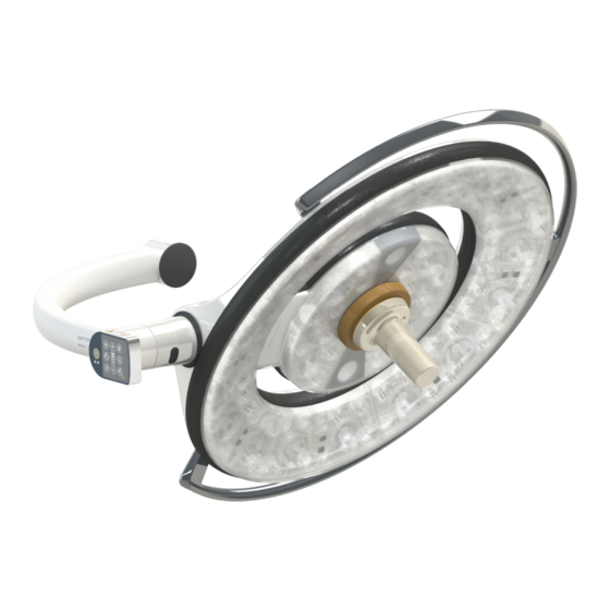
Introduction Product overview 1.6.1 Components 1.6.1.1 Lightheads Fig. 2: Maquet PowerLED II 700 and Maquet PowerLED II 500 lightheads Each lighthead comprises the following components: • Handle mount and sterilisable handle • Control keypad with antibacterial film • Outer handle coated in antibacterial paint •... - Page 13 The light field diameter variation function can be used to adjust the size of the light field so that it matches the dimensions of the incision. The Maquet PowerLED II lighting system provides three diameter settings on the Maquet PowerLED II 700 (small, medium, and large) and two settings on the Maquet PowerLED II 500 (small and medium).
- Page 14 It provides the surgical team and the anaesthetist with minimal lighting during minimally invasive procedures. It also creates a calm atmosphere to welcome pa- tients, thereby minimising stress. Maquet PowerLED II 14 / 116 IFU 01811 EN 10...
- Page 15 Prolonged exposure to laser light may result in eye damage. Do not direct a laser beam into the patient’s unprotected eyes. Users must not look directly into the laser beam. Maquet PowerLED II 15 / 116 IFU 01811 EN 10...
-
Page 16: Screen Holder Built Into The Device
Introduction Product overview 1.6.1.2 Screen holder built into the device Fig. 8: Screen holders available with Maquet PowerLED II 1 MHS0 3 XHD1 2 XHS0 Maquet PowerLED II 16 / 116 IFU 01811 EN 10... -
Page 17: Monitor Mount Built Into The Device
Fig. 9: SC05 camera mount 1.6.2 Options 1.6.2.1 Wall-mounted remote control panels Fig. 10: Wall-mounted control keypads Recessed version Power supply version Surface-mounted version Wall-mounted control keypad Recessed version with front panel Maquet PowerLED II 17 / 116 IFU 01811 EN 10... -
Page 18: Comfort Light
This function forms a low-intensity light field around the main surgical site. The reduced contrast resulting from this additional peripheral lighting enhances the comfort and visual performance of the surgical team, in particular by reducing perceived glare. Maquet PowerLED II 18 / 116 IFU 01811 EN 10... -
Page 19: Video
1.6.2.4 Colour temperature 3800 K 4300 K Fig. 14: Colour temperature 3800 K and 4300 K The Maquet PowerLED II surgical light is available in two colour temperature versions: 3800 K and 4300 K. Maquet PowerLED II 19 / 116 IFU 01811 EN 10... -
Page 20: Handle Mounts
Mount for STG HLX 01 handle Adapter for Devon® or Deroyal® disposable handle. Two versions are available: With (ARD569204989) or without (ARD569204990) TILT function (light field diameter variation using the handle) Maquet PowerLED II 20 / 116 IFU 01811 EN 10... -
Page 21: Options For Mhs0
3 Handle option (three possibilities, mounts to the left or to the right of the screen) 3a PSX MH handle mount 3b HLX MH handle mount 3c DAX MH handle mount Maquet PowerLED II 21 / 116 IFU 01811 EN 10... -
Page 22: Options For Xhs0
Options for XHS0 1 Rear Box 2 Screen holder plate XH 3 Handle option (three possibilities) 3a PSX XH handle mount 3b HLX XH handle mount 3c DAX XH handle mount Maquet PowerLED II 22 / 116 IFU 01811 EN 10... -
Page 23: Option For Xhd1
Introduction Product overview 1.6.2.8 Option for XHD1 Fig. 18: Option for XHD1 1 Screen Holder Plate PSX XHD1 3 Screen Holder Plate DAX XHD1 2 Screen Holder Plate HLX XHD1 Maquet PowerLED II 23 / 116 IFU 01811 EN 10... -
Page 24: Options For Camera Mounts
Product overview 1.6.2.9 Options for camera mounts Fig. 19: Options available with camera mounts 1 PSX handle mount for SC05 3 DEVON/DEROYAL® handle mount for SC05 2 HLX handle mount for SC05 Maquet PowerLED II 24 / 116 IFU 01811 EN 10... -
Page 25: Accessories
They ensure operating fluidity by keeping the surgical area clear during training phases, and facilitate monitoring of the surgeons’ actions, enabling their needs to be better anticipated. Maquet PowerLED II 25 / 116 IFU 01811 EN 10... - Page 26 E-Pan Tilt feature The E-Pan Tilt function allows the user to focus on a region of interest, and move that area, without having to move the light or the camera. Maquet PowerLED II 26 / 116 IFU 01811 EN 10...
-
Page 27: Lead Screens
LMD module The LMD system is compatible only with lightheads whose serial number is greater than 520000. If this is not the case, the LMD module flashes and does not operate. Maquet PowerLED II 27 / 116 IFU 01811 EN 10... -
Page 28: Sterilisable Handles
CS 10008 Ardon - 45074 Orléans cedex 2 - France YYYY-MM-DD XXXXXX ARDXXXXXXXXX PWDTXXXXXXXXXXXXXXX Maquet PowerLED II (XX)XXXXXXXXXXXXXX(XX)XXXXXX(XX)XXXXXX(XXX)ARDLCAXXXXXX(XX)XXXXXXXX AC 100-240 V 50/60 Hz 400 VA AC 24 V 50/60 Hz 400 VA DC 24 V 400 VA ANSI/AAMI ES60601-1 :2005 + AMD (2012) CAN/CSA-C22.2 NO. -
Page 29: Standards Applied
EN 60825-1:2014 ation and requirements Ordinance 384/2020 INMETRO Certification - Compliance assessment re- quirements for equipment under Health Surveillance Tab. 4: Compliance with product standards *only for pre-wired 4K configurations Quality management: Maquet PowerLED II 29 / 116 IFU 01811 EN 10... - Page 30 Packaging and Waste Management SJ/T 11365-2006 2006 Administrative Measure on the Control of Pollution caused by Electronic Information Products Chines RoHS (Restriction of Hazardous Substances) Tab. 6: Environmental standards and regulations Maquet PowerLED II 30 / 116 IFU 01811 EN 10...
-
Page 31: Information Relating To Intended Use
Compliance with market standards Information relating to intended use 1.9.1 Intended use The Maquet PowerLED II range is designed to illuminate the body of a patient during surgical op- erations, diagnostics or treatment. Maquet PowerLED II 31 / 116 IFU 01811 EN 10... -
Page 32: Indications
Introduction Primary purpose 1.9.2 Indications The Maquet PowerLED II range is intended to be used for any type of surgery, treatment or ex- amination requiring a specific type of lighting. 1.9.3 Intended users • The device may be operated only by medical staff who have read this manual. -
Page 33: Instructions For Reducing The Environmental Impact
This 10-year service lifetime applies subject to annual periodic checks being performed by per- sonnel trained and approved by Getinge; see Maintenance schedule [8 Page 103]. After this time, if the device is still in use, an inspection must be carried out by personnel trained and ap- proved by Getinge to ensure the continued safety of the device. -
Page 34: Safety-Related Information
The user must be vigilant and must ad- just the level of illumination to suit the patient concerned, particularly during a lengthy procedure. Maquet PowerLED II 34 / 116 IFU 01811 EN 10... -
Page 35: Electrical
Anyone not trained in installation, maintenance or decommissioning opera- tions is exposed to the risk of injury or electric shock. Installation, maintenance and decommissioning of the device or components of the device must be performed by a Getinge technician or a Getinge-trained service technician. AR NI NG... -
Page 36: Infection
Label Meaning Laser radiation. Do not look into the beam. Class 2 laser device. Laser radiation. Do not look into the beam. Class 2 laser device. Tab. 10: Safety label on the product Maquet PowerLED II 36 / 116 IFU 01811 EN 10... -
Page 37: Control Interfaces
Wall-mounted control keypad (optional) Touchscreen control panel (optional) The light can also be controlled via external control equipment provided by an in- tegrator. Contact your Getinge representative for more information. Contact your Getinge representative for more information. Maquet PowerLED II... -
Page 38: Lighthead Control Keypad
Battery indicator 10 AIM mode Adjustment of illumination 11 Ambient light mode Light field diameter variation 12 Laser positioning mode* Camera zoom 13 Laser safety symbol Plus (increase the level) Maquet PowerLED II 38 / 116 IFU 01811 EN 10... -
Page 39: Wall-Mounted Control Keypad
Light field diameter variation 14 Battery capacity Camera zoom 15 Battery level indicator Plus (increase the level) 16 Warning indicator Level indicator 17 Battery indicator Minus (reduce the level) 18 Laser safety symbol Maquet PowerLED II 39 / 116 IFU 01811 EN 10... -
Page 40: Touchscreen Control Panel
Active area Menu bar Ref. Description Area of the screen used to display the fault indicator, battery indicator, time, Getinge logo and customer logo. Area of the screen used to access the menus: home screen, presets, functions and set- tings. - Page 41 Press the clock icon to access the date and time settings. Getinge logo ▪ Press the Getinge logo to access product maintenance information. ▪ Press the Getinge logo a second time to access a menu reserved for Getinge technicians and qualified personnel, see Groups of people. Tab. 12:...
- Page 42 Battery tests Press the Battery Tests icon to access the backup tests page. Return Press the return button to return to the previous screen. Tab. 13: Touchscreen control panel status bar Maquet PowerLED II 42 / 116 IFU 01811 EN 10...
-
Page 43: Use
Half-rings on spring arms 1. Check that the half-rings on the spring arms are in place in their slots. 2. If a problem is noted, contact technical support. Fig. 37: Half-rings Maquet PowerLED II 43 / 116 IFU 01811 EN 10... - Page 44 2. Check that the lighthead cover are in the proper position and in good condition. 3. If a problem is noted, contact technical support. Fig. 40: Silicone caps and lighthead cover Maquet PowerLED II 44 / 116 IFU 01811 EN 10...
- Page 45 2. Press the ON/OFF button for 5 seconds. Ø All buttons and warning indicators are backlit. 3. If a problem is noted, contact technical support. Fig. 43: Condition of lighthead keypad Maquet PowerLED II 45 / 116 IFU 01811 EN 10...
- Page 46 Fig. 45: Screen holder caps Holding the handle mount 1. Pull along the handle interface axis to en- sure that it holds properly. Fig. 46: Holding the handle mount Maquet PowerLED II 46 / 116 IFU 01811 EN 10...
- Page 47 (From the wall- mounted control keypad [8 Page 94]) or via the touchscreen control panel (From the touchscreen control panel). 2. If the test fails, contact technical support. Fig. 48: Battery backup test Maquet PowerLED II 47 / 116 IFU 01811 EN 10...
-
Page 48: Controlling The Light
2. Press the On/Off button and hold it until the lighthead button turns off. Ø The LED sectors on the lighthead are turned off in sequence once the button is released. Maquet PowerLED II 48 / 116 IFU 01811 EN 10... -
Page 49: From The Touchscreen Control Panel
2. Press Lighthead ON/OFF Ø Lighthead 1 and the lighthead 1 operation indicator are turned off. 3. Proceed in the same way for all lightheads that are on. Ø The entire light is now off. Maquet PowerLED II 49 / 116 IFU 01811 EN 10... -
Page 50: Adjusting The Illumination
3. Press Minus to decrease the light field diameter of the lighthead(s). The Maquet PowerLED II 700 lighthead has three light field diameter levels and the Maquet PowerLED II 500 lighthead has two. Maquet PowerLED II 50 / 116 IFU 01811 EN 10... -
Page 51: From The Touchscreen Control Panel
Ø When enabled, the button is blue. 2. Press Increase diameter to increase the light field diameter of the lighthead(s) 3. Press Decrease diameter to decrease the light field diameter of the lighthead(s) Maquet PowerLED II 51 / 116 IFU 01811 EN 10... -
Page 52: Ambient Light
Ø The button is backlit on the keypad. 2. Press Plus to increase the light intensity level of the lighthead(s) 3. Press Minus to decrease the light intensity level of the lighthead(s) Maquet PowerLED II 52 / 116 IFU 01811 EN 10... -
Page 53: From The Touchscreen Control Panel
Ø When enabled, the button is blue. 2. Press Plus to increase the light intensity level of the lighthead(s) 3. Press Minus to decrease the light intensity level of the lighthead(s) Maquet PowerLED II 53 / 116 IFU 01811 EN 10... -
Page 54: Aim
2. When AIM mode is enabled, press Minus to decrease the light intensity level of the light- head(s). Boost mode is not available when AIM mode is enabled. In this case, the light has 10 illumination levels. Maquet PowerLED II 54 / 116 IFU 01811 EN 10... -
Page 55: From The Touchscreen Control Panel
Adjusting the light field diameter with AIM 1. Press Increase diameter to increase the light field diameter of the lighthead(s). 2. Press Decrease diameter to decrease the light field diameter of the lighthead(s). Maquet PowerLED II 55 / 116 IFU 01811 EN 10... -
Page 56: Comfort Light (Available Only With The Touchscreen Control Panel)
2. When Comfort Light mode is enabled, press the Comfort Light mode button to disable it. Ø The button turns off and Comfort Light mode is disabled on the lighthead(s) concerned. Maquet PowerLED II 56 / 116 IFU 01811 EN 10... -
Page 57: Synchronising The Lightheads
Ø The lightheads are no longer synchronised. Special case: To synchronise lightheads with ambient light mode, this mode must be active on the lightheads concerned before synchronisation. Maquet PowerLED II 57 / 116 IFU 01811 EN 10... -
Page 58: From The Touchscreen Control Panel
Ø The lightheads are desynchronised. Special case: To synchronise lightheads with ambient light mode, this mode must be active on the lightheads concerned before synchronisation. Maquet PowerLED II 58 / 116 IFU 01811 EN 10... -
Page 59: Lmd (With Touchscreen Control Panel Only)
(orange gauge above the reference value). The lighthead is at its maximum and the luminance remains below the set value (orange gauge below the reference value). Tab. 14: Luminance levels Maquet PowerLED II 59 / 116 IFU 01811 EN 10... -
Page 60: Presets (With Touchscreen Control Panel Only)
1. Adjust the light settings to the configuration desired for the preset. 2. Press Store preset Ø The preset data entry window is displayed (see opposite) showing the selected preset Maquet PowerLED II 60 / 116 IFU 01811 EN 10... -
Page 61: Factory Presets
Gynae tomy paedic gery surgery On/Off ̶ ̶ Zoom ̶ ̶ ̶ Auto Auto ̶ Auto Auto Contrast ̶ High Medium ̶ Standard High Tab. 17: Factory default camera presets Maquet PowerLED II 61 / 116 IFU 01811 EN 10... -
Page 62: Installing Or Removing A Sterilisable Handle
3. Turn the handle until a second click is heard. 4. Check that the handle is firmly in place. Ø The handle is now locked in place and ready for use. Maquet PowerLED II 62 / 116 IFU 01811 EN 10... -
Page 63: Installing Or Removing An Stg Hlx 01 Sterilisable Handle
Ø The locking button pops out of its housing. 4. Check that the handle is firmly in place. Ø The handle is now locked in place and ready for use. Maquet PowerLED II 63 / 116 IFU 01811 EN 10... -
Page 64: Installing And Removing Devon® Or Deroyal® Handles
Installing a DEVON® or DEROYAL® clip-on handle Installing a DEVON® or DEROYAL® clip-on handle 1. Screw the handle fully onto the mount. Ø The handle is now ready for use. Maquet PowerLED II 64 / 116 IFU 01811 EN 10... -
Page 65: Installing Or Removing An Stg Psx Vz 01 Sterilisable Handle
Fig. 69: Installing an STG PSX VZ 01 sterilisable handle Removing an STG PSX VZ 01 sterilisable handle 1. Press the locking button. 2. Remove the handle. Fig. 70: Removing an STG PSX VZ 01 sterilis- able handle Maquet PowerLED II 65 / 116 IFU 01811 EN 10... -
Page 66: Positioning The Light
– For sterile personnel: using the sterile handle provided for this purpose in the centre of the lighthead – For non-sterile personnel: by handling the lighthead either directly or using its outer handle Maquet PowerLED II 66 / 116 IFU 01811 EN 10... - Page 67 Rotation angles with SATX suspension and SF arm + 45° 360° + 45° 360° 270° - 70° 360° 360° - 70° 360° 280° 280° 260° 260° Fig. 75: Rotation angles with SATX suspension and DFarm Maquet PowerLED II 67 / 116 IFU 01811 EN 10...
-
Page 68: Laser Positioning Assistance
Ø The lighthead is then at the optimum distance from the area to be illuminated. 3. Press the Laser button again to turn off the laser manually before the 20 seconds have elapsed. Maquet PowerLED II 68 / 116 IFU 01811 EN 10... -
Page 69: From The Touchscreen Control Panel
Ø The light output level is reduced and two laser dots appear for 20 seconds. 3. Position the lighthead so as to bring the two dots closer together. Ø The lighthead is then at the optimum distance from the area to be illuminated. Maquet PowerLED II 69 / 116 IFU 01811 EN 10... -
Page 70: Pre-Positioning Examples
The suspension arms and spring arms should be located either side of the table, to avoid cluttering the area above the patient and the surgeon’s head. • The two lights should be located on either side of the surgeon’s shoulders. Maquet PowerLED II 70 / 116 IFU 01811 EN 10... - Page 71 Pre-positioning for plastic surgery For plastic surgery, it is recommended to have two lightheads of the same size so as to ensure that exactly the same lighting is provided symmetrically. Maquet PowerLED II 71 / 116 IFU 01811 EN 10...
-
Page 72: Installing Or Removing A Quick Lock + Device
Rotate the camera so as to align it with the keyed slot on the base • Insert until it clicks. • Check that the handle mount is fastened securely by moving the lighthead. • The Quick Lock + device is installed. Maquet PowerLED II 72 / 116 IFU 01811 EN 10... -
Page 73: Removing The Quick Lock + Handle Mount Or Camera
For the wall-mounted control keypad, first select the lighthead to be adjusted. Adjusting the camera zoom 1. Press Camera Zoom 2. Press Plus or Minus to modify the zoom level Maquet PowerLED II 73 / 116 IFU 01811 EN 10... -
Page 74: Control The Fhd Camera From The Touchscreen Control Panel
Pausing the camera 1. Press Camera pause to pause the camera. Ø The button is lit blue and the retransmitted image is frozen. 2. Press Camera pause again to resume video transmission. Maquet PowerLED II 74 / 116 IFU 01811 EN 10... - Page 75 3. Press Manual balance twice to set the white balance on the basis of the target under the camera. Ø The selected button is lit blue and the white balance is set. Maquet PowerLED II 75 / 116 IFU 01811 EN 10...
- Page 76 Fig. 92: Contrast adjustment Adjusting the contrast 1. Press Contrast to access the contrast adjustment menu. 2. Press Increase contrast or Decrease contrast to select one of the three contrast levels Maquet PowerLED II 76 / 116 IFU 01811 EN 10...
-
Page 77: Control The 4K Camera From The Touchscreen Control Panel
1. Press the Camera pause button to pause the camera. Ø The button is lit blue and the retransmitted image is frozen. 2. Press the Camera pause button again to resume video transmission. Maquet PowerLED II 77 / 116 IFU 01811 EN 10... - Page 78 Ø The button is lit blue and the camera focus is automatic. 3. Position the camera at the desired distance. 4. Press the Manual Focus button Ø The button is lit blue and the camera focus is fixed. Maquet PowerLED II 78 / 116 IFU 01811 EN 10...
- Page 79 E-Pan Tilt function. Ø The function settings page is displayed. 2. Press the E-Pan OFF button to disable the E-Pan Tilt function. Ø The function is disabled. Maquet PowerLED II 79 / 116 IFU 01811 EN 10...
- Page 80 Ø The selected button is lit blue and the white balance is applied. Adjusting the white balance manually 1. Press the White Balance button 2. Place a uniform white surface under the camera. Maquet PowerLED II 80 / 116 IFU 01811 EN 10...
- Page 81 3. Press the Exposure Plus button to increase the exposure or on Exposure Minus decrease the exposure. Fig. 102: Image rotation Inverting the transmitted image 1. Press the Rotate 180° button to rotate the transmitted image 180°. Maquet PowerLED II 81 / 116 IFU 01811 EN 10...
-
Page 82: Orienting The Camera
1. Install a sterilisable handle on the camera (Installing or removing an STG PSX VZ 01 sterilisable handle [8 Page 65]). 2. Use the handle to rotate the camera. Ø The image is rotated on the screen. Fig. 104: Orienting the camera Maquet PowerLED II 82 / 116 IFU 01811 EN 10... -
Page 83: Positioning The Screen Holder(S)
Handling of the screen holder by the non-sterile team 1. Move the device by grasping the flat-panel monitor , the screen holder frame the fork handle or the rear box Fig. 106: Handling by the non-sterile team Maquet PowerLED II 83 / 116 IFU 01811 EN 10... - Page 84 Screen holder MHS0 270° 360° 315° +45°/-70° ̶ XHS0 270° 360° 315° +45°/-70° -45°/+90° XHD1 270° 360° 330° +45°/-70° -60°/+10° Tab. 19: Rotation amplitude values (in degrees) on a SATX suspension Maquet PowerLED II 84 / 116 IFU 01811 EN 10...
-
Page 85: Screen Holder Pre-Positioning Examples
• They must be positioned such that the surgeon can see all of the information. • They must be at a sufficient distance to avoid any contact with sterile personnel. Maquet PowerLED II 85 / 116 IFU 01811 EN 10... -
Page 86: Positioning The Camera Mount
During the procedure, the sterile team must handle the device using the ster- ilisable handles. On an HLX handle, the locking button is not sterile. Non- sterile personnel must not come into contact with the sterilisable handles. Maquet PowerLED II 86 / 116 IFU 01811 EN 10... - Page 87 For non-sterile personnel: Using the fixed uprights or the mount Degrees of rotation Fig. 113: Degrees of rotation of camera mounts SC05 SAX: 360° 360° 360° +45° / -70° 120° SATX: 270° Maquet PowerLED II 87 / 116 IFU 01811 EN 10...
-
Page 88: Settings And Functions
Ø The tilt handle adjustment page is displayed. Accessing configuration information 1. Press Settings in the menu bar. Ø The Settings page is displayed (see above). 2. Press Information Ø The configuration information page is displayed. Maquet PowerLED II 88 / 116 IFU 01811 EN 10... -
Page 89: Screen Brightness
Ø The screen brightness varies as shown by the brightness level indicator 2. Press OK to confirm the brightness changes, or Cancel to cancel the changes in pro- gress. Ø The configured brightness is stored and applied. Maquet PowerLED II 89 / 116 IFU 01811 EN 10... -
Page 90: Date And Time, And Stopwatch/Timer Functions
Ø The selected field is shown with a blue border. 3. Use the keypad to enter the desired value and then press OK to confirm the changes. Ø The data entry window closes and the changes take effect. Maquet PowerLED II 90 / 116 IFU 01811 EN 10... -
Page 91: Tilt Handle
Adjusting the illumination using the tilt handle 1. Turn the handle to adjust the light intensity, light field diameter or colour temperature to the chosen setting. The Tilt handle does not have limit stops. Maquet PowerLED II 91 / 116 IFU 01811 EN 10... -
Page 92: Information
Press Maintenance to display the dates on which maintenance was performed and the Getinge contact details. Press Power supply to display a history of power cuts. Press Battery Backup to display a history of battery backup tests. -
Page 93: Backup Battery
Lighthead keypad backup operation indicators Indicators Description Meaning One LED lit red External backup at a very low level (with Getinge backup only) Two LEDs lit red External backup at a low level (with Getinge backup only) Three LEDs lit orange... -
Page 94: Performing Battery Tests
Ø If the test is successful, the battery level indicator flashes green. If the test fails, the battery level indicator flashes red. 3. If the test fails, contact the Getinge technical service department. 4. Press Battery backup test again. Ø The battery level indicator stops flashing. -
Page 95: From The Touchscreen Control Panel
4. If the test fails, press Maintenance information to access the maintenance information page, and then call the Getinge technical service department. Running a battery lifetime test (only with a Getinge backup) 1. Turn off the light. 2. Press Battery Tests in the menu bar. -
Page 96: Troubleshooting
Powered from mains Orange indicator Powered from backup supply Flashing red indicator Powered from backup supply (only available with Getinge The batteries are almost totally discharged and the backup) system will lose power in a few minutes. Tab. 25: Battery indicators 5.1.2... -
Page 97: Potential Failures And Troubleshooting
Have the brakes replaced by a trained technician Incorrect adjustment of the Have the brakes adjusted by a brake(s) trained technician Device too stiff to manoeuvre Mechanical lock Contact the Getinge technical department Tab. 29: Mechanical anomalies and malfunctions Electronics/Optics Anomaly Likely cause Corrective action... - Page 98 PWD2 A B C D, where: Faulty lighthead (700 or 500) Address of faulty lighthead (1, 2, or 3) Fault type Faulty component In all cases, please contact Getinge technical support. Maquet PowerLED II 98 / 116 IFU 01811 EN 10...
-
Page 99: Cleaning / Disinfection / Sterilisation
(soap solution) containing active substances such as detergents and phosphates. Do not use abrasive products, as these could damage the surfaces. 3. Remove the cleaner using a cloth moistened with water and then wipe with a dry cloth. Maquet PowerLED II 99 / 116 IFU 01811 EN 10... -
Page 100: Disinfecting The Device
▪ Ethylene diamine tetraacetic acid (2.5%) Tab. 31: Lists of active substances suitable for use Examples of commercially available products tested • ANIOS product®** : Surfa’Safe®** • Other products: 20% or 45% isopropyl alcohol Maquet PowerLED II 100 / 116 IFU 01811 EN 10... -
Page 101: Cleaning And Sterilising Maquet Sterigrip Sterilisable Handles
Typical cleaning cycles in a washer-disinfector The use of non-enzymatic detergents is recommended. Enzymatic detergents may damage the handles. Never soak the handles in these detergents for prolonged periods. Rinse thor- oughly. Maquet PowerLED II 101 / 116 IFU 01811 EN 10... -
Page 102: Sterilisation Of The Maquet Sterigrip Handles
4. Run the sterilisation cycle according to the steriliser manufacturer’s instructions. Sterilisation cycle Temperature Time (°C) (min) (min) ATNC (Prion) ̶ Prevacuum Tab. 33: Example of a steam sterilisation cycle Maquet PowerLED II 102 / 116 IFU 01811 EN 10... -
Page 103: Maintenance
If the device has a Getinge backup system, perform a battery lifetime test. To test from the wall- mounted control keypad, the lightheads must be turned off and the test start button must be backlit to enable the test to be started. -
Page 104: Technical Specifications
Tab. 36: Table of optical data for Maquet PowerLED II 700 and Maquet PowerLED II 500 lightheads For all light field diameters In nominal mode The colour temperature is selected at the time of order Maquet PowerLED II 104 / 116 IFU 01811 EN 10... - Page 105 Wavelength 650 nm Beam divergence 0.58 mrad Maximum power output 1 mW Tab. 39: Laser specifications See also Certificat_lifetime_PWDII [} 106] Certificat_ROA_PWDII [} 107] Optical values measured with the largest light field diameter Maquet PowerLED II 105 / 116 IFU 01811 EN 10...
- Page 106 LED Life Time Certificate Maquet PowerLED II 500 Maquet PowerLED II 700 IES LM-80 Test report for LED According to IES LM-80 standard, lumen maintenance is the remaining luminous flux output (% of the initial output) at a selected operating time.
- Page 107 EN 62471 Certificate PowerLED II 500 PowerLED II 700 Measurements conditions The irradiance measurements are performed at 1 meter, which is considered the working distance of the light. The radiance measurements are performed with a field of view of 11 mrad, which is considered representative of the usual eye’s exposure (several short time exposures).
-
Page 108: Mechanical Specifications
16 kg XHS021 21 kg XHD127 27 kg Tab. 42: Mechanical specifications of the screen holders For more information, refer to the Maquet PowerLED II installation instructions. 8.2.4 Mechanical compatibility Device Compatibility Camera for SC05 Camera with 1/4'’ screw thread weighing less than 5 kg... -
Page 109: Electrical Characteristics
Tab. 44: Table of electrical specifications (Class I appliance) Electrical compatibility with other devices Compatible electrical devices Compatibility External control device RS232 / MaqBus / Dry contact Tab. 45: Electrical compatibility table Maquet PowerLED II 109 / 116 IFU 01811 EN 10... -
Page 110: Technical Specifications Of The Cameras And Receiver
3G-SDI Weight (without/with mounting bracket) 230 g / 260 g Dimensions with mounting bracket (L x W x H) 143 × 93 × 32 mm Tab. 47: VP01 RECEIVER technical specifications Maquet PowerLED II 110 / 116 IFU 01811 EN 10... - Page 111 Wired (Coaxial) RS232 interface Weight (without sterile handle) 780 g Dimensions (without sterile handle) (Diam. x H) 124 x 181 mm Tab. 48: Technical specifications of the OHDII 4K QL+ VP11 camera Maquet PowerLED II 111 / 116 IFU 01811 EN 10...
-
Page 112: Other Characteristics
Protection rating for the device as a whole IP 20 Protection rating of the lightheads IP 44 EMDN code Z12010701 GMDN code 12,282 CE marking year 2018 Tab. 49: Specifications relating to standards and regulations Maquet PowerLED II 112 / 116 IFU 01811 EN 10... -
Page 113: Emc Declaration
Do not use this device except in a professional healthcare facility. Electromagnetic interference may result in temporary extinction or temporary flick- ering of the light, which will recover its initial settings once the interference has ceased. Maquet PowerLED II 113 / 116 IFU 01811 EN 10... -
Page 114: Fcc Part 15 (Usa Only)
B defined in CISPR 11 is normally required), this device may not provide sufficient pro- tection for radio frequency communication services. The user may need to take corrective measures, such as relocating or re-orienting the device. Maquet PowerLED II 114 / 116 IFU 01811 EN 10... -
Page 115: Waste Management
For full information relating to processing of the device once it is no longer in use, see the Maquet PowerLED II Decommissioning Instructions (ARD01815). Contact your local Getinge representat- ive to obtain a copy of this document. - Page 116 *MAQUET POWERLED II, AIM, LMD, COMFORT LIGHT, LASER POSITIONING, FSP, POWERLED, SATELITE, MAQUET, GETINGE and GETINGE GROUP are trademarks or registered trademarks of Getinge AB, its divisions or its subsidiaries. **VALIA is a trademark or registered trademark of Ondal Holding GmbH, its divisions or its...
Need help?
Do you have a question about the Maquet PowerLED II and is the answer not in the manual?
Questions and answers