
Related Manuals for Getinge Arjohuntleigh Citadel


Summary of Contents for Getinge Arjohuntleigh Citadel
- Page 1 Citadel Bed Frame System Instructions for Use ...with people in mind 830.331 Rev C • 12/2018...
- Page 2 Design Policy and Copyright ® and ™ are trademarks belonging to the ArjoHuntleigh group of companies unless otherwise stated. © ArjoHuntleigh 2017 As our policy is one of continuous improvement, we reserve the right to modify designs without prior notice. The content of this publication may not be copied either wholly or in part without the consent of ArjoHuntleigh.
-
Page 3: Table Of Contents
Table of Contents General Warnings ...................5 • Safety Information ..................8 Introduction ....................11 • Product Overview ..................11 Clinical Applications ..................14 • Intended Use ....................14 • Indications ....................14 • Contraindications ..................14 • General Product Information ..............15 • Precautions ....................15 Installation .....................17 • Weighing System Preparation ..............17 •... - Page 4 • Weighing Initialization ................41 • Weighing ....................41 • Weighing Units ..................42 • Auto Compensation ..................42 • Weighing System Error Codes ..............43 • Angle Indication ..................43 • VariZone Patient Movement / Exit Detection ...........44 • VariZone Operation .................45 • Anti-Entrapment System ................46 •...
-
Page 5: General Warnings
GENERAL WARNINGS The following warnings should be considered prior to using this product: Before using the bed, make sure that the power in rating on the To make sure the patient can use the bed safely, their age and The use of head down tilt (Trendelenburg) or foot down tilt (reverse Trendelenburg) may be contraindicated for certain All accessories added to the system reduce the safe working If the power cord or plug is damaged, the complete assembly... - Page 6 Make sure the locking mechanisms are securely engaged when Prior to engaging any mattress turn feature, make sure that bed frame has side rails and that all side rails are fully engaged in feature on any mattress system when patient restraints are in Patient restraints should be used in compliance with all applicable local regulations and in accordance with the Patient restraints, even when correctly used, can result in...
- Page 7 The weighing system MUST be zeroed every time a new patient The weighing system MUST be zeroed every time a mattress is The weighing system cannot be zeroed if a mattress or and care should be performed under the supervision of an on battery power if the function has not been locked on the To prevent cross contamination or equipment damage, be cleaned during use and between patients according to the...
-
Page 8: Safety Information
Safety Information General Protocols – Follow all applicable safety rules and institution protocols concerning patient and caregiver safety. Brakes – Set all caster brakes before transferring patient. Bed Height – To minimize risk of falls or injury, the bed should always be in the lowest practical position when the patient is unattended. - Page 9 caregivers, with facility protocols in mind. Caregivers should assess risks and bed) in conjunction with individual patient needs, and should discuss use or non-use with patient and / or family. Consider not only the clinical and other needs of the patient but also the risks of fatal or serious injury from falling out of bed and from patient entrapment in or around the side rails, restraints or other accessories.
- Page 10 Turning - Prior to engaging any mattress turn feature, make sure that bed frame has side rails and that all side rails are fully engaged in their full upright and locked position. Do not activate the turning feature on any mattress system when patient restraints are in use.
-
Page 11: Introduction
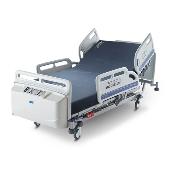
INTRODUCTION These instructions contain information for the installation, use and maintenance of the ArjoHuntleigh Citadel™ Bed Frame System. These beds have multiple functions to provide the optimum nursing position for both patient and caregiver. Product Overview A. Head Board M. Weighing / Movement Detection B. - Page 12 All Citadel beds have the following standard features: • Folding split side rails with integrated bed controls • Electrical adjustment of bed height and leg section elevation • Electrically operated retracting backrest • Auto-Chair facility • Electrical adjustment of head down tilt (Trendelenburg) and foot down tilt (reverse Trendelenburg) •...
- Page 13 chosen options are indicated by the equipment model number. located on the bed frame below the head board. Before using the bed, make sure that the Power in rating on the Citadel Bed Frame System ArjoHuntleigh AB 270 kg Hans Michelsensgatan 10 595 lb 211 20 Malmö, SWEDEN 0086...
-
Page 14: Clinical Applications
CLINICAL APPLICATIONS To make sure the patient can use the bed safely, their age and The use of head down tilt (Trendelenburg) or foot down tilt (reverse Trendelenburg) may be contraindicated for certain Intended Use The Citadel Bed Frame System is intended for the acute and post-acute care environments. -
Page 15: General Product Information
General Product Information All accessories added to the system reduce the safe working Safe working load (SWL)....... 270 kg (595 lb) Maximum patient weight........ 227 kg (500 lb) The recommended patient height is between 146 cm (58 in) and 190 cm (75 in). - Page 16 Citadel Bed Frame System...
-
Page 17: Installation
INSTALLATION The following chapter describes how to install the bed. Weighing System Preparation To prevent damage to the weighing mechanism, replace the When replacing the transport locking bolts care must be taken to Remove the four transport locking bolts (1) and washers (2); there are two locking bolts at the head end of the bed and two at the foot end. -
Page 18: Electricity Supply
Electricity Supply If the power cord or plug is damaged, the complete assembly Make sure the power cord does not become entangled with moving parts of the bed or trapped between the bed frame and Unplug the power cord from the electricity supply, and store it, months, connect the bed to the electricity supply for at least 24 hours to allow the backup battery to recharge fully;... -
Page 19: Potential Equalization Terminal
A potential equalization terminal (Figure 5, item 1) is located at the foot end of the bed. When other electrical equipment is within reach of the patient or caregiver, together their potential equalization terminals. Electrical Connections The Citadel bed contains the following electrical connections. Frame: Citadel™... -
Page 20: Nurse Call And Rs232 Connections
Nurse Call and RS232 Connections 1. Connect one end of the nurse call cable to the 37-pin D-type outlet, located below the head end of the bed on the patient's right hand side. 2. Connect the other end of the nurse call cable to a compatible nurse call system. -
Page 21: Auxiliary Power Outlet (Optional Feature)
Auxiliary Power Outlet (Optional Feature) • 115 VAC / 7A • 230 VAC / 4A This outlet does not remain powered when the bed is on battery Auxiliary power outlet is provided as a convenience for powering devices intended to be placed at or near the foot end of the bed. Skin IQ Family Power Cable The cable should only be used to power the Skin IQ Family of Skin IQ Power Cable is provided as a convenience for powering Skin IQ. -
Page 22: Non Powered 5Th Wheel Operation (Optional Feature)
Non Powered 5th Wheel Operation (Optional Feature) The Non Powered 5th wheel accessory provides improved mobility and steering assistance for the Citadel and Enterprise series beds. The Non Powered 5th wheel reduces physical demands on the caregiver during patient transport. The improved steering assistance provides more controlled turning around corners, through doorways and positioning of the bed within rooms. -
Page 23: Citadel Patient Therapy System Connections
Citadel Patient Therapy System Connections The following connections are provided for attaching a Citadel Patient Therapy System to the Citadel Bed Frame System. More details on proper connection can be found in the Citadel Patient Therapy System Instructions for Use. Air Hoses AC Power Connector Communications Connector... -
Page 24: Safeset
When assessing the suitability of a mattress for use with side rails, the following factors should be considered: • The bed is designed to provide an acceptable side rail height when used with a foam mattress between 15 cm (6 in) and 20.5 cm (8 in). •... - Page 25 A label on the calf extension sheet indicates the mattress size: 15 - 20.5 cm (6 - 8 in) 830.229 Rev B Entrapment hazards may exist when using a very soft mattress, The maximum recommended standard mattress thickness for Valve Covers If a non-integrated mattress is used, make sure that the valve covers are in Citadel Bed Frame System...
-
Page 26: Operating Instructions
OPERATING INSTRUCTIONS It is recommended that all chapters of this manual be reviewed prior to product use. Carefully read the Contraindications, Risks and Precautions Safety Information sections in the Introduction chapter of this manual prior to installing a mattress and placing a patient on the Citadel Bed Frame System. -
Page 27: Drainage Bag Rails
Drainage Bag Rails The maximum weight that can be safely supported by each Items placed on the drainage bag rails (such as patient drains and urine bags) are included in the weighing calculation, and Rails (1) to support drainage bags, etc. are located below the thigh and backrest sections on either side of the bed. - Page 28 To extend the bed frame: 1. Level the deck before adjusting the bed length. 2. Rotate the blue extension locking handle (1) located under the foot end of bed and pull out the bed frame (2) to the required position and release the handle.
-
Page 29: Foot Pedal For Adjustment Of Bed Height (Optional Feature)
Foot Pedal for Adjustment of Bed Height (Optional Feature) Bed height can be adjusted from bed control panels and from the foot pedal switch located near the foot end of the bed. Lift cover of switch with foot and press left side to raise the bed height. Press right side of switch to lower bed height. -
Page 30: Side Rails
Head End Brake Pedals Additional brake pedals are located at the head end of the bed. These operate in the same way as the foot end pedals. Side Rails age, size and condition of the patient before allowing the use of Side rails are not intended to restrain patients who make a Make sure that the mattress is suitable for use with side rails - To prevent possible entrapment, make sure the patient’s head... -
Page 31: Head And Foot Boards
To raise the side rail: 1. Hold either side rail handle. Pull the split side rail up and away from the bed until it locks in the raised position. 2. The head end and foot end side rails operate in the same way. Make sure the locking mechanism is securely engaged when the Head and Foot Boards patient. - Page 32 Patient restraints are not intended as substitutes for good Patient restraints can be attached to either side of the deck frame. Attachment points are provided on the backrest (1), thigh section (2) and calf section (3). Restraint straps should be attached as shown below to prevent sliding along the deck frame.
-
Page 33: Under Bed Light
Under Bed Light The under bed light can be turned on from the Nurse Control Panel unless the bed is in its low-power state. Backup Battery To make sure the battery is kept fully charged and prevent damage to the battery, the bed should be connected to the The backup battery will power Skin IQ for four hours before The backup battery allows operation of the bed for short periods when it is unplugged from the electricity supply or in emergency situations when the... -
Page 34: Recharging The Backup Battery
Recharging the Backup Battery If the battery is left uncharged for long periods, its operational life To recharge the battery, connect the bed to the electricity supply. Allow at least eight hours to recharge the battery when it is completely uncharged. While the battery is recharging, the ACP battery indicator LED lights yellow. -
Page 35: Attendant Control Panel (Acp), Nurse Control Panel And Patient Control Panel
Attendant Control Panel (ACP), Nurse Control Panel and Patient Control Panel Figure 25: Patient Control Panel Power On Indicator - Indicator LED lights when the bed is connected to the electricity supply. Battery Indicator - Indicates status of the battery system. Refer to the section Backup Battery on page 32. - Page 36 Backrest Angle - These buttons raise and lower the backrest. The backrest will pause when it reaches an angle approximately 30º above the horizontal. Thigh Section - These buttons raise and lower the thigh section. section will be in the fowler position (angled downwards). Calf Section - These buttons raise and lower the calf section.
- Page 37 • When all functions are locked or unlocked as required, press the settings are stored. When a function is locked, any associated functions are Function lockout settings are retained if the bed is disconnected from the electricity supply. Under bed Light either side of the bed.
-
Page 38: Patient Handsets (Optional Feature)
Patient Handsets (Optional Feature) The controls on these handsets operate in the same way as those on the side rails. Store the handsets on the split side rail using the clip on the The patient should be shown how to use the handset by the Take care not to squeeze or trap the handset cable between Weigh Scale Panels (With and Without Unit Selection) or removed without proper use of AutoComp, lack of regular... - Page 39 The weighing system should only be used in closely supervised as additions to the bed) can be controlled as described in the Approval No. UK2823 2009/23/EC Max 270 kg Min 10 kg e = 500 g Figure 27 Weigh Scale Panels (Dependent on Country) Display to show other information.
-
Page 40: Weighing Accuracy
Weighing Accuracy Patient weighing system 500g (1 lb) Minimum capacity 10kg (20 lb) Maximum capacity 250kg (550 lb) Approvals Complies with 90/383/EEC Class III. external factors. For best performance, observe the following precautions: • Position the bed such that the lower frame and upper frame do not touch one another. -
Page 41: Weighing Initialization
Weighing Initialization The weighing system MUST be zeroed every time a new patient The weighing system MUST be zeroed every time a mattress is The weighing system cannot be zeroed if a mattress or It is not recommended to zero the bed or take a weight reading After connecting the bed to the electricity supply, the weighing system must be initialized as follows: 3. -
Page 42: Weighing Units
Weighing Units On select models, weight readings can be viewed in pounds or kilograms by pressing the Select Units button. An indicator LED next to the display will light to show the selected units (lb or kg), if equipped. To lock the Select Units button so that the display always shows readings in either pounds or kilograms, if equipped: 1. -
Page 43: Weighing System Error Codes
Weighing System Error Codes Error codes are shown on the display. They are used to indicate a problem with the weighing system; this may be due to an operator error or a possible fault condition. The table below shows common error code displays with their causes and solutions. -
Page 44: Varizone Patient Movement / Exit Detection
VariZone Patient Movement / Exit Detection The patient movement detection function should be checked periodically for correct operation and before each new patient validated by the user to make sure correct operation with the The patient movement detection system can be set to alarm when undesired movement of the patient occurs. -
Page 45: Varizone Operation
VariZone Operation Before activating patient movement detection, make sure that: • • All additional items (example: accessories) have been accounted for using the Auto Compensation function. • The weighing system display is blank. Before using patient movement detection, verify that the alarm To activate patient movement detection, press and hold either the In Bed button or Egress button for two seconds. -
Page 46: Anti-Entrapment System
To cancel the alarm or deactivate patient movement detection: Press the In Bed button or Egress button once. The alarm will be silenced and the threshold display indicator will go out to show that movement detection is deactivated. To silence the alarm: Press the Bed Exit Silence button. The alarm will be silenced for three minutes and the VariZone system will be re-enabled once patient weight is returned to the bed. -
Page 47: Safeset™ (Optional Feature)
SafeSet™ (Optional Feature) SafeSet visual status indicators intended for patients at risk SafeSet visual status indicators provide a quick visual indication of optimum SafeSet visual status indicators show four safety-critical bed parameters: • Brake setting • Side rail position • Mattress platform height •... - Page 48 The indicator lights are positioned so they can be easily seen at a distance. A sensor (2) will automatically reduce the brightness of the indicator lights in low light conditions, except when an indicator light is showing an unsafe (red) condition.
-
Page 49: Rs232 Connection
RS232 Connection The bed continuously transmits data about its status through an RS232 connection at the head end of the bed (see page 19). The transmitted data can be recorded by a compatible device. Data is transmitted every ten seconds and includes the following information: •... -
Page 50: Controls For Television And Lighting (Optional Feature)
Controls for Television and Lighting (Optional Feature) Button controls for television and lighting are located on the head end side rails. The side rails also contain loudspeakers for television sound. 3. Decrease volume 4. Increase volume 8. Channel down 9. Channel up The bed must be connected to a compatible Headwall system for the TV and The controls have been designed to be compatible with the majority of TV sets found in hospitals. -
Page 51: Patient Placement
PATIENT PLACEMENT It is recommended that all chapters of this manual be reviewed prior to product use. Carefully read the Contraindications, Risks and Precautions, Safety Information sections in the Introduction chapter of this manual prior to placing a patient on the Citadel Bed Frame System. Power On 1. -
Page 52: Completion Of Patient Placement
Completion of Patient Placement 1. Press the In Bed or Egress buttons to activate and set the desired sensitivity of the VariZone patient movement detection system. Adjust patient surface for patient comfort. 2. Bring the bed to the lowest practical height for patient comfort. 3. -
Page 53: Nursing Care
NURSING CARE It is recommended that all chapters of this manual be reviewed prior to product use. Carefully read the Contraindications, Risks and Precautions Safety Information sections of the Introduction chapter of this manual prior to performing nursing care for a patient on the Citadel Bed Frame System. -
Page 54: Cpr Backrest Release
CPR Backrest Release CPR backrest release handles are located below the calf section on either side of the bed. This will lower the backrest to enable cardiopulmonary resuscitation to be performed. Patient Bathing 1. Adjust height and level patient surface to facilitate ease of bathing. frame controls. -
Page 55: Patient Transfer From The Citadel Bed Frame System
Patient Transfer from the Citadel Bed Frame System 1. Level patient surface. 2. Adjust height of patient surface to same level as surface to which patient is being transferred. 3. Make sure caster brakes on both units are locked. 4. Lower side rails. 5. - Page 56 Citadel Bed Frame System...
-
Page 57: Care And Cleaning
CARE AND CLEANING Deck Sections The four deck sections (backrest, seat, thigh and calf) can be removed by Figure 35: Deck sections (top view) To replace each section, make sure it is correctly positioned on the deck Replace the calf extension sheet (1) by clipping it over the end of the deck frame. -
Page 58: General Recommendations
The bed should be cleaned and disinfected weekly, and before a new patient is placed on the bed. Cleaning 1. Remove the mattress and all accessories from the bed. 2. The head and foot boards and mattress platform sheets should be removed from the bed for cleaning. -
Page 59: Cleaning The Citadel Bed Frame System While In Use
Always disconnect the Citadel Bed Frame System from mains Cleaning the Citadel Bed Frame System While in Use 4. If possible, remove the patient from the bed prior to cleaning. Daily care and cleaning consists of wiping down all surfaces and side rails (as needed) during patient bathing. - Page 60 Citadel Bed Frame System...
-
Page 61: Preventive Maintenance
PREVENTIVE MAINTENANCE This product is subject to wear and tear during use. To make sure that it procedures should be carried out at the intervals shown. This list indicates the minimum recommended level of preventive out when the product is subjected to heavy use, aggressive Failure to carry out these checks, or continuing to use the product if a fault is found, may compromise the safety of both Actions to be completed by caregiver... -
Page 62: Weighing System
Yearly Check that the bed operates correctly using the backup battery as described in the Battery test section below Check operation of the casters, paying special attention to braking and steering functions Check that the bed extension locks securely in both non-transport positions Examine the power cord and mains plug;... -
Page 63: Troubleshooting
TROUBLESHOOTING If the equipment fails to operate correctly, the table below suggests some simple checks and corrective actions. If these steps fail to resolve the problem, contact ArjoHuntleigh or an ArjoHuntleigh-approved service agent. Symptom Possible Cause Action Audible tone when using Bed is operating from the Check that the power supply cord is the bed... -
Page 64: Error Codes
Symptom Possible Cause Action Weighing system display System fault or operator Refer to the table of error codes on shows unknown value error page 43 TV / lighting controls not Nurse call cable not Check to ensure cable is of correct working connected or wrong type type and properly connected... -
Page 65: Fault Indications
Fault Indications any of the indications below, contact ArjoHuntleigh or an ArjoHuntleigh-approved service agent. Indication Possible cause Height actuator fault (head end) Height actuator fault (foot end) Backrest actuator fault Thigh section actuator fault Calf section actuator fault Deck height, head down tilt, backrest and thigh section indicator LEDs Control unit fault Product Lifetime safety, provided it has been maintained and operated in conditions of normal use in... - Page 66 Citadel Bed Frame System...
-
Page 67: Electromagnetic Compability (Emc)
ELECTROMAGNETIC COMPABILITY (EMC) Product has been tested for compliance with current regulatory standards regarding its capacity to block EMI (electromagnetic interference) from external sources. Some procedures can help reduce electromagnetic interferences: • Use only ArjoHuntleigh cables and spare parts to avoid increased emissions or decreased immunity which can compromise the correct functioning of the equipment. - Page 68 Immunity test Compliance level Electromagnetic environment test level - guidance Floors should be wood, Electrostatic ±2kV, ±4kV, ±8kV, ±2kV, ±4kV, ±8kV, discharge ±15kV air ±15kV air are covered with synthetic (ESD) IEC ±8kV contact ±8kV contact material the relative humidity 61000-4-2 level should be at least 30% 3V in 0,15 MHz to...
- Page 69 Immunity test Compliance level Electromagnetic environment test level - guidance Floors should be wood, Electrostatic ±2kV, ±4kV, ±8kV, ±2kV, ±4kV, ±8kV, discharge ±15kV air ±15kV air are covered with synthetic (ESD) IEC ±8kV contact ±8kV contact material the relative humidity 61000-4-2 level should be at least 30% Surge...
-
Page 70: Warranty And Service
WARRANTY AND SERVICE ArjoHuntleigh standard terms and conditions apply to all sales; a copy is available on request. The standard terms and conditions contain full details of warranty terms and do not limit the statutory rights of the consumer. For service, maintenance and any questions regarding this product, please Questions and Information section. -
Page 71: Specifications
SPECIFICATIONS General Safe working load 270 kg (595 lb) Maximum patient weight 227 kg (500 lb) Product weight (approx.) 200 kg (441 lb) Audible noise <35dB approx. Operating conditions Temperature 14°C to 35°C (58°F to 95°F) Relative humidity 20% to 80% noncondensing Altitude Up to 2000 m (6,562 ft) Electrical data... - Page 72 Position 2 (Standard) 202 cm (80 in) Position 3 (Extended) 214 cm (84 in) Overall width 103 cm (40.6 in) Height of mattress platform (measurement taken from centre and edge of seat section With 125 mm (5 in) castors 34 cm to 78 cm (13.3 to 30.7 in) Flat Deck Sheets With 150 mm (6 in) castors 36 cm to 80 cm (14.1 to 31.5 in) Flat Deck Sheets Head down tilt angle...
-
Page 73: Explanation Of Symbols Used
EXPLANATION OF SYMBOLS USED Temperature Low and High Limits E348583 IPX4 No Hooks Protected against ingress of liquids Important Operational Information Auxiliary Power Outlet Warning of possible hazard to system, Refer to Instructions for Use Conforms with the Medical Device Directive (93/42/EEC) and has been Serial Number subject to the conformity procedures laid... - Page 74 Maximum Patient Weight Safe Working Load Tripping Hazard Do Not Shower Protective earth (ground) Cardiopulmonary Resuscitation Recommended Mattress Size Patient Height 15 - 20.5 cm (6 - 8 in) 830.209 Rev D 830.229 Rev C Torque Citadel Bed Frame System...
- Page 75 AUSTRALIA FRANCE Arjo Australia Pty Ltd Arjo SAS Arjo Polska Sp. z o.o. 78, Forsyth Street 2 Avenue Alcide de Gasperi O’Connor CS 70133 AU-6163 Western Australia FR-59436 RONCQ CEDEX Tel: +48 61 662 15 50 Tel: +61 89337 4111 Tél: +33 (0) 3 20 28 13 13 Fax: +48 61 662 15 90 Free: +1 800 072 040...
- Page 76 ArjoHuntleigh AB Hans Michelsensgatan 10 211 20 Malmö, Sweden www.arjohuntleigh.com ArjoHuntleigh is a world-leading provider of integrated products and solutions that improve the lives of patients and residents with reduced mobility. We help healthcare facilities deliver wellness and effective everyday care, early mobilisation, safe patient handling, venous thromboembolism prevention, pressure injury prevention, hygiene routines, bariatric care and diagnostics.
Need help?
Do you have a question about the Arjohuntleigh Citadel and is the answer not in the manual?
Questions and answers