
Subscribe to Our Youtube Channel
Related Manuals for IEI Technology AESQ170-969


Summary of Contents for IEI Technology AESQ170-969
- Page 1 AESQ170-969 Single Board Computer Full Size PICMG 1.3 CPU Card supports ® Intel Q170 Chipset User's Manual Rev. 1.04 Date: September 11, 2019...
-
Page 2: Table Of Contents
Packing List ................19 Optional Items ................20 Chapter 3 Connectors ............. 24 Peripheral Interface Connectors ..........24 3.1.1 AESQ170-969 Layout ................24 3.1.2 Peripheral Interface Connectors ............24 3.1.3 External Interface Panel Connectors ..........26 Internal Peripheral Connectors ..........26 3.2.1 +12V ATX Power Connector .............. - Page 3 3.2.11 Front Panel Connector ................ 33 3.2.12 I C Connector ..................33 3.2.13 Internal DisplayPort Connector ............34 3.2.14 iRIS-2400 Module Slot (AESQ170-969-i2-R10 Only) ......35 3.2.15 Keyboard and Mouse Connector ............35 3.2.16 LAN LED Connectors ................36 3.2.17 Parallel Port Connector ..............37 3.2.18 PCIe Mini Slot ..................
- Page 4 Preface ® 4.12 Intel AMT Setup Procedure ............. 71 4.13 IPMI Setup Procedure (AESQ170-969-i2-R10 Only) ....72 Chapter 5 BIOS ................ 73 Introduction ................73 Main .................... 74 Advanced ................... 76 5.3.1 Trusted Computing ................76 5.3.2 ACPI Settings ..................77 5.3.3 AMT Configuration ................
-
Page 5: List Of Figures
List of Figures Figure 1-1: AESQ170-969 Series ..............11 Figure 1-2: Connectors ................13 Figure 1-3: AESQ170-969 Dimensions (mm) ..........14 Figure 1-4: Data Flow Diagram ..............15 Figure 3-1: Peripheral Interface Connectors ..........24 Figure 3-2: +12V ATX Power Connector Pinout Location ......26 Figure 3-3: Audio Connector Location ............ - Page 6 Preface Figure 4-1: Disengage the CPU Socket Load Lever ........53 Figure 4-2: Remove Protective Cover ............54 Figure 4-3: Insert the Socket LGA1151 CPU ..........55 Figure 4-4: Close the Socket LGA1151 ............55 Figure 4-5: Cooling Kit Support Bracket ............ 56 Figure 4-6: DIMM Installation ..............
-
Page 7: List Of Tables
Preface List of Tables Table 1-1: AESQ170-969 Model Variations ..........12 Table 1-2: AESQ170-969 Specifications ............. 18 Table 2-1: Packing List ................20 Table 2-2: Optional Items ................23 Table 3-1: Peripheral Interface Connectors ..........26 Table 3-2: External Peripheral Connectors ..........26 Table 3-3: +12V ATX Power Connector Pinouts ......... - Page 8 Preface Table 4-1: AT/ATX Power Mode Switch Settings........63 Table 4-2: BIOS Switch Settings ..............64 Table 4-3: PCIe x16 Channel Mode Setup ..........65 Table 4-4: Flash Descriptor Security Override Jumper Settings ..... 65 Table 4-5: BIOS Options and Configured USB Ports ........ 66 Table 4-6: USB Power Source Setup ............
-
Page 9: Bios Menus
Preface BIOS Menus BIOS Menu 1: Main ..................75 BIOS Menu 2: Advanced ................76 BIOS Menu 3: Trusted Computing .............. 77 BIOS Menu 4: ACPI Configuration .............. 77 BIOS Menu 5: AMT Configuration ............... 78 BIOS Menu 6: Super IO Configuration ............79 BIOS Menu 7: Serial Port n Configuration Menu ........ -
Page 10: Revision
Preface Revision Date Version Changes September 11, 1.04 Modified the available options in the DVMT Pre- 2019 Allocated BIOS option in Section 5.4.1.1 September 20, 1.03 Modified pin locations of JSPI1 and JSPI2 2018 connectors November 13, 1.02 Updated supported CPUs 2017 June 1, 2017 1.01... -
Page 11: Manual Conventions
Preface All registered trademarks and product names mentioned herein are used for identification purposes only and may be trademarks and/or registered trademarks of their respective owners. Manual Conventions WARNING Warnings appear where overlooked details may cause damage to the equipment or result in personal injury. Warnings should be taken seriously. -
Page 12: Chapter 1 Introduction
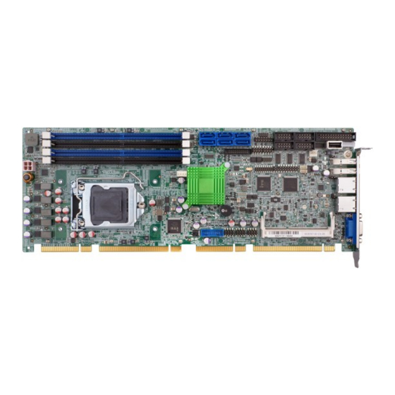
Chapter 1 Introduction Chapter 1 Introduction 1.1 Introduction Figure 1-1: AESQ170-969 Series The AESQ170-969 is a full-size PICMG 1.3 CPU card. It accepts a Socket ® ® ® LGA1151 6th/7th generation Intel Core™ i7/i5/i3, Pentium or Celeron processor and supports four 288-pin 2133 MHz dual-channel DDR4 DIMM modules up to 64 GB. -
Page 13: Features
AMT 11.0 support) -size/half-size PCIe Mini slot supports mSATA A connector -232 serial ports -232/422/485 serial ports 1.4 Connectors The connectors on the AESQ170-969 are shown in the figure below. -
Page 14: Dimensions
Chapter 1 Introduction Figure 1-2: Connectors 1.5 Dimensions The main dimensions of the AESQ170-969 are shown in the diagram below. -
Page 15: Figure 1-3: Aesq170-969 Dimensions (Mm)
Chapter 1 Introduction Figure 1-3: AESQ170-969 Dimensions (mm) -
Page 16: Data Flow
Chapter 1 Introduction 1.6 Data Flow Figure 1-4 shows the data flow between the system chipset, the CPU and other components installed on the motherboard. Figure 1-4: Data Flow Diagram... -
Page 17: Technical Specifications
Chapter 1 Introduction 1.7 Technical Specifications The AESQ170-969 technical specifications are listed below. Specification/Model AESQ170-969 Form Factor Full-size PICMG 1.3 CPU card ® 6th/7th generation LGA1151 Intel Core™ i7/i5/i3, CPU Supported ® ® Pentium or Celeron ® Intel Q170 Four 288-pin 2133/1867 MHz dual-channel... - Page 18 One 14-pin header (power LED, HDD LED, speaker, Front Panel power button, reset button) One 4-pin wafer connector iRIS (Remote One iRIS-2400 module slot (AESQ170-969-i2-R10 Intelligent System) only) Internal DisplayPort One 20-pin box header Keyboard and One internal keyboard and mouse connector (6-pin...
-
Page 19: Table 1-2: Aesq170-969 Specifications
5VSB@0.15A (4.0 GHz Intel® Core™ i7-6700K CPU Consumption with four 16 GB 2133 MHz DDR4 memory) Operating -20℃~60℃ Temperature Storage -30℃~70℃ Temperature Operating Humidity 5%~95% (non-condensing) Physical Specifications Dimensions 338 mm×126 mm Weight (GW/NW) 1000g / 420g Table 1-2: AESQ170-969 Specifications... -
Page 20: Chapter 2 Packing List
Only handle the edges of the PCB: Don't touch the surface of the motherboard. Hold the motherboard by the edges when handling. 2.2 Unpacking Precautions When the AESQ170-969 is unpacked, please do the following: -static guidelines above. ... -
Page 21: Optional Items
Chapter 2 Packing List Quantity Item and Part Number Image AESQ170-969 Series CPU card SATA cable (P/N: 32000-062800-RS) Mini jumper pack Standoff and screw (for half-size PCIe Mini card) Utility CD Table 2-1: Packing List 2.4 Optional Items The following are optional components which may be separately purchased:... - Page 22 Chapter 2 Packing List Item and Part Number Image SATA power cable (P/N: 32102-000100-200-RS) LPT cable (P/N: 32200-015100-RS) 7.1-channel HD audio kit with Realtek ALC892 audio codec supporting dual audio stream (P/N: AC-KIT-892HD-R10) LGA1150 cooler kit (high-performance compatible, 95W) (P/N: CF-1150SA-R10) LGA1150 cooler kit (high-performance compatible, 65W) (P/N: CF-1150SB-R11) LGA1150 cooler kit (1U chassis compatible,...
- Page 23 Chapter 2 Packing List Item and Part Number Image LGA1150 cooler kit (high-performance compatible, 95W) (P/N: CF-1150SE-R11) LGA1150 cooler kit (1U chassis compatible, 54W) (P/N: CF-1150SF-R10) DisplayPort to HDMI converter board (for iDP connector) (P/N: DP-HDMI-R10) DisplayPort to LVDS converter board (for iDP connector) (P/N: DP-LVDS-R10) DisplayPort to VGA converter board (for iDP...
-
Page 24: Table 2-2: Optional Items
Chapter 2 Packing List Item and Part Number Image DisplayPort to DisplayPort converter board (for iDP connector) (P/N: DP-DP-R10) SATA to IDE/CompactFlash® converter board (P/N: SAIDE-KIT01-R10) Table 2-2: Optional Items... -
Page 25: Chapter 3 Connectors
Chapter 3 Connectors 3.1 Peripheral Interface Connectors This chapter details all the peripheral interface connectors. 3.1.1 AESQ170-969 Layout The figure below shows all the peripheral interface connectors. Figure 3-1: Peripheral Interface Connectors 3.1.2 Peripheral Interface Connectors The table below lists all the connectors on the board. - Page 26 Front panel connector 14-pin header F_PANEL1 I2C connector 4-pin wafer I2C1 Internal DisplayPort connector 20-pin box header iRIS-2400 module slot iRIS-2400 module slot IPMI1 (AESQ170-969-i2-R10 only) Keyboard and mouse 6-pin wafer KB_MS1 connector LAN LED connectors 2-pin header LED_LAN1, LED_LAN2...
-
Page 27: External Interface Panel Connectors
USB3_1, USB3_2 VGA connector 15-pin female VGA1 Table 3-2: External Peripheral Connectors 3.2 Internal Peripheral Connectors The section describes all of the connectors on the AESQ170-969. 3.2.1 +12V ATX Power Connector CN Label: CPU12V1 CN Type: 4-pin Molex power connector, p=4.2 mm... -
Page 28: Audio Kit Connector
Chapter 3 Connectors Description Description +12V +12V Table 3-3: +12V ATX Power Connector Pinouts 3.2.2 Audio Kit Connector CN Label: J_AUDIO1 CN Type: 10-pin header, p=2.00 mm CN Location: See Figure 3-3 CN Pinouts: See Table 3-4 This connector allows connection to an external audio kit. Figure 3-3: Audio Connector Location Description Description... -
Page 29: Chassis Intrusion Connector
Chapter 3 Connectors regulations. CN Label: BAT1 CN Type: 2-pin wafer, p=1.25 mm CN Location: See Figure 3-4 CN Pinouts: See Table 3-5 This is connected to the system battery. The battery provides power to the system clock to retain the time when power is turned off. Figure 3-4: Battery Connector Location Description VBATT... -
Page 30: Crt Fw Update Connector
Chapter 3 Connectors Description +3.3VSB CHASSIS OPEN Table 3-6: Chassis Intrusion Connector Pinouts 3.2.5 CRT FW Update Connector CN Label: J_CRTFW1 CN Type: 3-pin header, p=2.00 mm CN Location: See Figure 3-6 CN Pinouts: See Table 3-7 The CRT FW update connector is used to update the CRT firmware. Figure 3-6: CRT FW Update Connector Location Description Table 3-7: CRT FW Update Connector Pinouts... -
Page 31: Digital I/O Connector
Chapter 3 Connectors Figure 3-7: DDR4 DIMM Socket Locations 3.2.7 Digital I/O Connector CN Label: DIO1 CN Type: 10-pin header, p=2.00 mm CN Location: See Figure 3-8 CN Pinouts: See Table 3-8 The digital I/O connector provides programmable input and output for external devices. -
Page 32: Fan Connector (Cpu)
Chapter 3 Connectors CN Label: CN Type: 18-pin header, p=2.00 mm CN Location: See Figure 3-9 CN Pinouts: See Table 3-9 The EC debug connector is used for EC debug. Figure 3-9: EC Debug Connector Location Description Description EC_EPP_STB# EC_EPP_AFD# EC_EPP_PD0 EC_EPP_PD1 EC_EPP_INIT#... -
Page 33: Fan Connectors (System)
Chapter 3 Connectors Figure 3-10: CPU Fan Connector Location Description +12V FANIO Table 3-10: CPU Fan Connector Pinouts 3.2.10 Fan Connectors (System) CN Label: SYS_FAN1 CN Type: 3-pin wafer, p=2.54 mm CN Location: See Figure 3-11 CN Pinouts: See Table 3-11 The fan connector attaches to a system cooling fan. -
Page 34: Front Panel Connector
Chapter 3 Connectors 3.2.11 Front Panel Connector CN Label: F_PANEL1 CN Type: 14-pin header, p=2.54 mm CN Location: See Figure 3-12 CN Pinouts: See Table 3-12 The front panel connector connects to the indicator LEDs and buttons on the computer's front panel. Figure 3-12: Front Panel Connector Location Function Description... -
Page 35: Internal Displayport Connector
Chapter 3 Connectors Figure 3-13: I C Connector Location Description I2C_DAT I2C_CLK Table 3-13: I C Connector Pinouts 3.2.13 Internal DisplayPort Connector CN Label: CN Type: 20-pin box header, p=2.00 mm CN Location: See Figure 3-14 CN Pinouts: See Table 3-14 The DisplayPort connector supports HDMI, LVDS, VGA, DVI and DisplayPort graphics interfaces with up to 3840×2160 resolutions. -
Page 36: Iris-2400 Module Slot (Aesq170-969-I2-R10 Only)
Figure 3-15: iRIS-2400 Module Slot Location WARNING: The iRIS-2400 module slot is designed to install the iRIS-2400 module only. DO NOT install other modules into the iRIS module slot. Doing so may cause damage to the AESQ170-969. 3.2.15 Keyboard and Mouse Connector CN Label:... -
Page 37: Lan Led Connectors
Chapter 3 Connectors The keyboard and mouse connector connects to a PS/2 Y-cable that can be connected to a PS/2 keyboard and mouse. Figure 3-16: Keyboard and Mouse Connector Location Description Mouse Data Mouse Clock Keyboard Data Keyboard Clock Table 3-15: Keyboard and Mouse Connector Pinouts 3.2.16 LAN LED Connectors CN Label:... -
Page 38: Parallel Port Connector
Chapter 3 Connectors Description +3.3V LAN1_LED_LINK#_AC Table 3-16: LAN1 LED Connector (LED_LAN1) Pinouts Description +3.3V LAN2_LED_LINK#_AC Table 3-17: LAN2 LED Connector (LED_LAN2) Pinouts 3.2.17 Parallel Port Connector CN Label: LPT1 CN Type: 26-pin box header, p=2.54 mm CN Location: See Figure 3-18 CN Pinouts: See Table 3-18 The parallel port connector connects to a parallel port connector interface or... -
Page 39: Pcie Mini Slot
Chapter 3 Connectors Description Description RPD5 RPD6 RPD7 SIO_ACK# SIO_BUSY SIO_PE SIO_SLCT Table 3-18: Parallel Port Connector Pinouts 3.2.18 PCIe Mini Slot CN Label: MPCIE1 CN Type: PCIe Mini slot CN Location: See Figure 3-19 CN Pinouts: See Table 3-19 The PCIe Mini slot is for installing a full-size/half-size PCIe Mini expansion card, such as an mSATA SSD or wireless LAN card. -
Page 40: Power Button
Chapter 3 Connectors Description Description 1.5V MSATA_CLK# MSATA _CLK PLTRST_N +3.3V PLTRST_N SATA_RX-/PCIE_RX- +3.3V SATA_RX+/PCIE_RX+ 26 1.5V SMB_CLK SATA_TX-/PCIE_TX- SMB_DATA SATA_TX+/PCIE_TX+ USB_DATA- USB_DATA+ +3.3V +3.3V +3.3V CLINK_CLK CLINK_DATA 1.5V CLINK_RST# MSATA_DET +3.3V Table 3-19: PCIe Mini Slot Pinouts 3.2.19 Power Button CN Label: PWR_SW1 CN Type:... -
Page 41: Serial Port Connectors
Chapter 3 Connectors Figure 3-20: Power Button Location 3.2.20 RS-232 Serial Port Connectors CN Label: COM1, COM2 CN Type: 10-pin box header, p=2.54 mm CN Location: See Figure 3-21 CN Pinouts: See Table 3-20 Each of these connectors provides RS-232 connections. Figure 3-21: RS-232 Serial Port Connector Locations Description Description... -
Page 42: Figure 3-22: Rs-232/422/485 Serial Port Connector Locations
Chapter 3 Connectors CN Label: COM3, COM4 CN Type: 10-pin box header, p=2.54 mm CN Location: See Figure 3-22 CN Pinouts: See Table 3-21 and Table 3-22 Each of these connectors provides RS-232/422/485 connections. NOTE: The communication protocol of the serial ports is set through the BIOS menu in “Advanced →Super IO Configuration→Serial Port 3/4 Configuration”. -
Page 43: Sata 6Gb/S Drive Connector
Chapter 3 Connectors RS-232 Pinouts RS-422 Pinouts RS-485 Pinouts Table 3-22: DB-9 RS-232/422/485 Pinouts 3.2.22 SATA 6Gb/s Drive Connector CN Label: S_ATA1, S_ATA2, S_ATA3, S_ATA4, S_ATA5, S_ATA6 CN Type: 7-pin SATA drive connector CN Location: See Figure 3-23 CN Pinouts: See Table 3-23 The SATA drive connectors can be connected to SATA drives and supports up to 6Gb/s data transfer rate. -
Page 44: Smbus Connector
Chapter 3 Connectors NOTE: If the user shorts the mSATA setup jumper (MSATA_SW1) to force the system to enable mSATA device or an mSATA device is detected, the S_ATA6 connector will be disabled. Please refer to Section 4.9.7 for detailed information. 3.2.23 SMBus Connector CN Label:... -
Page 45: Spi Flash Connector, Ec
Chapter 3 Connectors Figure 3-25: SPI Flash Connector Location Description Description +3.3V SPI_CS SPI_CLK_SW SPI_SO_SW SPI_SI_SW Table 3-25: SPI Flash Connector Pinouts 3.2.25 SPI Flash Connector, EC CN Label: JSPI2 CN Type: 8-pin header, p=2.54 mm CN Location: See Figure 3-26 CN Pinouts: See Table 3-26 The SPI flash connector is used to flash the EC ROM. -
Page 46: Tpm Connector
Chapter 3 Connectors Description Description SPI_SO SPI_SI Table 3-26: SPI EC Flash Connector Pinouts 3.2.26 TPM Connector CN Label: TPM1 CN Type: 20-pin header, p=2.54 mm CN Location: See Figure 3-27 CN Pinouts: See Table 3-27 The TPM connector connects to a TPM module. Figure 3-27: TPM Connector Location Description Description... -
Page 47: Usb 2.0 Connectors
Chapter 3 Connectors 3.2.27 USB 2.0 Connectors CN Label: USB1, USB2, USB3 CN Type: 8-pin header, p=2.54 mm CN Location: See Figure 3-28 CN Pinouts: See Table 3-28 The USB 2.0 connectors connect to USB 2.0 devices. Each pin header provides two USB 2.0 ports. -
Page 48: Usb 3.1 Gen 1 Connector
Chapter 3 Connectors Description DATA- DATA+ GROUND Table 3-29: USB 2.0 Connector (Type A) Pinouts 3.2.29 USB 3.1 Gen 1 Connector CN Label: USB3_34 CN Type: 19-pin box header, p=2 mm CN Location: See Figure 3-30 CN Pinouts: See Table 3-30 The USB 3.1 Gen 1 connector connects to USB 3.1 Gen 1 devices. -
Page 49: External Peripheral Interface Connector Panel
Chapter 3 Connectors Description Description Table 3-30: USB 3.1 Gen 1 Connector Pinouts 3.3 External Peripheral Interface Connector Panel The figure below shows the external peripheral interface connector (EPIC) panel. The EPIC panel consists of the following: Figure 3-31: External Peripheral Interface Connector 3.3.1 Ethernet Connectors CN Label:... -
Page 50: Usb 3.1 Gen 1 Connectors
CN Label: USB3_1, USB3_2 CN Type: USB 3.1 Gen 1 Type A CN Location: See Figure 3-31 CN Pinouts: See Table 3-32 There are two external USB 3.1 Gen 1 connectors on the AESQ170-969. Description Description VBUS STDA_SSRX_N STDA_SSRX_P GND_DRAIN STDA_SSTX_N STDA_SSTX_P Table 3-32: USB 3.1 Gen 1 Port Pinouts... -
Page 51: Figure 3-33: Vga Connector
Chapter 3 Connectors Figure 3-33: VGA Connector Description Description GREEN BLUE HOT PLUG DETECT DDCDA HSYNC VSYNC DDCCLK Table 3-33: VGA Connector Pinouts... -
Page 52: Chapter 4 Installation
Electrostatic discharge (ESD) can cause serious damage to electronic components, including the AESQ170-969. Dry climates are especially susceptible to ESD. It is therefore critical that whenever the AESQ170-969 or any other electrical component is handled, the following anti-static precautions are strictly adhered to. -
Page 53: Socket Lga1151 Cpu Installation
Turn all power to the AESQ170-969 off: When working with the AESQ170-969, make sure that it is disconnected from all power supplies and that no electricity is being fed into the system. Before and during the installation of the AESQ170-969, DO NOT: ... -
Page 54: Figure 4-1: Disengage The Cpu Socket Load Lever
Chapter 4 Installation DO NOT touch the pins at the bottom of the CPU. When handling the CPU, only hold it on the sides. To install the CPU, follow the steps below. Step 1: Disengage the load lever by pressing the lever down and slightly outward to clear the retention tab. -
Page 55: Figure 4-2: Remove Protective Cover
Chapter 4 Installation Figure 4-2: Remove Protective Cover Step 3: Inspect the CPU socket. Make sure there are no bent pins and make sure the socket contacts are free of foreign material. If any debris is found, remove it with compressed air. Step 4: Orientate the CPU properly. -
Page 56: Figure 4-3: Insert The Socket Lga1151 Cpu
Chapter 4 Installation Figure 4-3: Insert the Socket LGA1151 CPU Step 8: Close the CPU socket. Close the load plate and pull the load lever back a little to have the load plate be able to secure to the knob. Engage the load lever by pushing it back to its original position (Figure 4-4). -
Page 57: Socket Lga1151 Cooling Kit Installation
Chapter 4 Installation 4.4 Socket LGA1151 Cooling Kit Installation WARNING: DO NOT attempt to install a push-pin cooling fan. The pre-installed support bracket prevents the board from bending and is ONLY compatible with captive screw type cooling fans. The cooling kit can be bought from IEI. The cooling kit has a heat sink and fan. WARNING: Do not wipe off (accidentally or otherwise) the pre-sprayed layer of thermal paste on the bottom of the heat sink. -
Page 58: Dimm Installation
Do not overtighten the screws. Step 5: Connect the fan cable. Connect the cooling kit fan cable to the CPU fan connector on the AESQ170-969. Carefully route the cable and avoid heat generating chips and fan blades. 4.5 DIMM Installation To install a DIMM, please follow the steps below and refer to Figure 4-6. -
Page 59: Iris-2400 Module Installation (Optional)
To install the iRIS-2400 module, please follow the steps below and refer to Figure 4-7. Figure 4-7: iRIS-2400 Module Installation Step 1: Locate the IPMI module slot. Place the AESQ170-969 on an anti- static pad. Step 2: Align the iRIS-2400 module with the iRIS module slot. Align the... -
Page 60: Full-Size Pcie Mini Card Installation
Chapter 4 Installation Step 3: Insert the iRIS-2400 module. Push the module in at a 20º angle (Figure 4-7). Step 4: Seat the iRIS-2400 module. Gently push downwards and the arms clip into place (Figure 4-7). 4.7 Full-size PCIe Mini Card Installation The PCIe Mini card slot allows installation of either a full-size or half-size PCIe Mini card. -
Page 61: Figure 4-9: Inserting The Full-Size Pcie Mini Card Into The Slot At An Angle
Chapter 4 Installation Figure 4-9: Inserting the Full-size PCIe Mini Card into the Slot at an Angle Step 4: Secure the full-size PCIe Mini card. Secure the full-size PCIe Mini card with the retention screw previously removed (Figure 4-10). Figure 4-10: Securing the Full-size PCIe Mini Card... -
Page 62: Half-Size Pcie Mini Card Installation
Chapter 4 Installation 4.8 Half-size PCIe Mini Card Installation The PCIe Mini card slot allows installation of either a full-size or half-size PCIe Mini card. To install a half-size PCIe Mini card, please follow the steps below. Step 1: Locate the PCIe Mini card slot. See Chapter 3. Step 2: Install the standoff to the screw hole for the half-size PCIe Mini card. -
Page 63: Figure 4-12: Inserting The Half-Size Pcie Mini Card Into The Slot At An Angle
Chapter 4 Installation Figure 4-12: Inserting the Half-size PCIe Mini Card into the Slot at an Angle Step 4: Secure the half-size PCIe Mini card. Secure the half-size PCIe Mini card with the supplied retention screw (Figure 4-13). Figure 4-13: Securing the Half-size PCIe Mini Card... -
Page 64: System Configuration
Chapter 4 Installation 4.9 System Configuration The system configuration should be performed before installation. 4.9.1 AT/ATX Power Mode Setting The AT and ATX power mode selection is made through the AT/ATX power mode switch which is shown in Figure 4-14. Figure 4-14: AT/ATX Power Mode Switch Location Setting Description... -
Page 65: Pcie X16 Channel Mode Setup
4.9.4 PCIe x16 Channel Mode Setup The AESQ170-969 supports one PCIe x16 interface on the backplane. The PCIe x16 channel mode setup is made through the BIOS menu in “Chipset → System Agent (SA) Configuration → PEG Port Configuration”. Use the... -
Page 66: Flash Descriptor Security Override Jumper
Chapter 4 Installation PEG Link Width Configuration BIOS option to configure the PCIe x16 channel mode. Options Description Sets the PCIe x16 link width as one PCIe x16 slot 1x16 (default) Sets the PCIe x16 link width as two PCIe x8 slots Sets the PCIe x16 link width as one PCIe x8 and two 1x8, 2x4 PCIe x4... -
Page 67: Usb Power Selection
Chapter 4 Installation Step 3: Remove the metal clip on the flash descriptor security override jumper or return to its default setting (short pin 1-2). Step 4: Restart the system. The system will reboot 2 ~ 3 times to complete the ME firmware update. -
Page 68: Internal Peripheral Device Connections
This section outlines the installation of peripheral devices to the onboard connectors. 4.10.1 SATA Drive Connection The AESQ170-969 is shipped with two SATA drive cables. To connect the SATA drives to the connectors, please follow the steps below. Step 1: Locate the connectors. The locations of the SATA drive connectors are shown in Chapter 3. -
Page 69: Figure 4-19: Sata Drive Cable Connection
Chapter 4 Installation Figure 4-19: SATA Drive Cable Connection Step 3: Connect the cable to the SATA disk. Connect the connector on the other end of the cable to the connector at the back of the SATA drive. See Figure 4-20. Step 4: Connect the SATA power cable. -
Page 70: Adding Usb 3.1 Gen 1 Drivers To A Windows 7 Installation Image
Chapter 4 Installation Figure 4-20: SATA Power Drive Connection The SATA power cable can be bought from us. See Optional Items in Section 2.4. 4.11 Adding USB 3.1 Gen 1 Drivers to a Windows 7 Installation Image The Windows 7 installation media does not include native driver support for USB 3.1 Gen 1. -
Page 71: Figure 4-21: Windows 7 Usb 3.0 Creator Utility
Chapter 4 Installation Step 1: Prepare a USB flash drive installer. On a working computer, use your Windows 7 DVD or ISO image to create a bootable USB flash drive. Step 2: Download the Windows 7 USB 3.0 Creator Utility. Step 3: Extract the downloaded file to a temporary folder on a computer where the user has logged in as the administrator. -
Page 72: Intel ® Amt Setup Procedure
Now the user can proceed with the Windows 7 installation using the updated installer. ® 4.12 Intel AMT Setup Procedure ® The AESQ170-969 is featured with the Intel Active Management Technology ® (AMT). To enable the Intel AMT function, follow the steps below. Step 1: Make sure at least one of the memory sockets is installed with a DDR4 DIMM. -
Page 73: Ipmi Setup Procedure (Aesq170-969-I2-R10 Only)
(IPMI) that helps lower the overall costs of server management by enabling users to maximize IT resources, save time and manage multiple systems. The AESQ170-969-i2 supports IPMI 2.0 through the optional iRIS-2400 module. Follow the steps below to setup IPMI. -
Page 74: Chapter 5 Bios
Chapter 5 BIOS Chapter 5 BIOS 5.1 Introduction The BIOS is programmed onto the BIOS chip. The BIOS setup program allows changes to certain system settings. This chapter outlines the options that can be changed. NOTE: Some of the BIOS options may vary throughout the life cycle of the product and are subject to change without prior notice. -
Page 75: Main
Chapter 5 BIOS Function Main Menu – Quit and not save changes into CMOS Status Page Setup Menu and Option Page Setup Menu – Exit current page and return to Main Menu General help, only for Status Page Setup Menu and Option Page Setup Menu Load previous values Load optimized defaults... - Page 76 Chapter 5 BIOS information. BIOS Menu 1: Main The Main menu has two user configurable fields: System Date [xx/xx/xx]...
-
Page 77: Advanced
Chapter 5 BIOS Use the System Date option to set the system date. Manually enter the day, month and year. System Time [xx:xx:xx] Use the System Time option to set the system time. Manually enter the hours, minutes and seconds. 5.3 Advanced Use the Advanced menu (BIOS Menu 2) to configure the CPU and peripheral devices through the following sub-menus:... -
Page 78: Acpi Settings
Chapter 5 BIOS BIOS Menu 3: Trusted Computing Security Device Support [Disable] Use the Security Device Support option to configure support for the TPM. Disable DEFAULT TPM support is disabled. TPM support is enabled. Enable 5.3.2 ACPI Settings The ACPI Settings menu (BIOS Menu 4) configures the Advanced Configuration and Power Interface (ACPI) options. -
Page 79: Amt Configuration
Chapter 5 BIOS ACPI Sleep State [S3 (Suspend to RAM)] Use the ACPI Sleep State option to specify the sleep state the system enters when it is not being used. S3 (Suspend DEFAULT The caches are flushed and the CPU is to RAM) powered off. -
Page 80: Super Io Configuration
Chapter 5 BIOS Disable DEFAULT Not perform ME unconfigure Enable To perform ME unconfigure 5.3.4 Super IO Configuration Use the Super IO Configuration menu (BIOS Menu 6) to set or change the configurations for the serial ports and parallel port. BIOS Menu 6: Super IO Configuration Case Open Detection [Disabled] Use the Case Open Detection option to enable or disable the case open... - Page 81 Chapter 5 BIOS BIOS Menu 7: Serial Port n Configuration Menu 5.3.4.1.1 Serial Port 1 Configuration Serial Port [Enabled] Use the Serial Port option to enable or disable the serial port. Disable Disable the serial port Enable DEFAULT Enable the serial port Change Settings [Auto] Use the Change Settings option to change the serial port IO port address and interrupt address.
- Page 82 Chapter 5 BIOS 5.3.4.1.2 Serial Port 2 Configuration Serial Port [Enabled] Use the Serial Port option to enable or disable the serial port. Disable Disable the serial port Enable DEFAULT Enable the serial port Change Settings [Auto] Use the Change Settings option to change the serial port IO port address and interrupt address.
- Page 83 Chapter 5 BIOS IRQ=11 the interrupt address is IRQ11 IO=3F8h; Serial Port I/O port address is 3F8h and IRQ=3, 4, 11 the interrupt address is IRQ3, 4, 11 IO=2F8h; Serial Port I/O port address is 2F8h and IRQ=3, 4, 11 the interrupt address is IRQ3, 4, 11 IO=3E8h;...
- Page 84 Chapter 5 BIOS IO=2D0h; Serial Port I/O port address is 2D0h and IRQ=3, 4, 11 the interrupt address is IRQ3, 4, 11 IO=2E0h; Serial Port I/O port address is 2E0h and IRQ=3, 4, 11 the interrupt address is IRQ3, 4, 11 Transfer Mode [RS232] The serial port allows setting the data transfer mode to RS-232, RS-422 or RS-485.
-
Page 85: Iwdd H/W Monitor
Chapter 5 BIOS 5.3.5 iWDD H/W Monitor The iWDD H/W Monitor menu (BIOS Menu 9) contains the fan configuration submenu, and displays operating temperature, fan speeds and system voltages. BIOS Menu 9: iWDD H/W Monitor PC Health Status The following system parameters and values are shown. The system parameters that are monitored are: ... -
Page 86: Rtc Wake Settings
Chapter 5 BIOS 5.3.5.1 Smart Fan Mode Configuration Use the Smart Fan Mode Configuration submenu (BIOS Menu 10) to configure fan speed settings. BIOS Menu 10: Smart Fan Mode Configuration CPU_FAN1 Smart Fan Control/SYS_FAN1 Smart Fan Control [Auto Mode] Use the CPU_FAN1 Smart Fan Control/SYS_FAN1 Smart Fan Control option to configure the CPU/system fan. -
Page 87: Serial Port Console Redirection
Chapter 5 BIOS BIOS Menu 11: RTC Wake Settings Wake system with Fixed Time [Disabled] Use the Wake system with Fixed Time option to enable or disable the system wake on alarm event. Disable DEFAULT The real time clock (RTC) cannot generate a wake event. - Page 88 Chapter 5 BIOS BIOS Menu 12: Serial Port Console Redirection Console Redirection [Disabled] Use Console Redirection option to enable or disable the console redirection function. Disable DEFAULT Disabled the console redirection function Enabled the console redirection function Enable The following options are available in the Console Redirection Settings submenu when the Console Redirection option is enabled.
- Page 89 Chapter 5 BIOS require lower speeds. 9600 Sets the serial port transmission speed at 9600. 19200 Sets the serial port transmission speed at 19200. Sets the serial port transmission speed at 57600 57600. 115200 DEFAULT Sets the serial port transmission speed at 115200.
-
Page 90: Cpu Configuration
Chapter 5 BIOS BIOS Menu 13: Legacy Console Redirection Settings Legacy Serial Redirection Port [COM1] Use the Legacy Serial Redirection Port option to select a COM port to display redirection of legacy OS and legacy OPROM messages. Configuration options are listed below. ... - Page 91 Chapter 5 BIOS BIOS Menu 14: CPU Configuration Hyper-threading [Enabled] Use the Hyper-threading BIOS option to enable or disable the Intel Hyper- Threading Technology. Disabled Disables the Intel Hyper-Threading Technology. DEFAULT Enables the Intel Hyper-Threading Enabled Technology. Active Processor Cores [All] Use the Active Processor Cores BIOS option to enable numbers of cores in the processor package.
-
Page 92: Sata Configuration
Chapter 5 BIOS Disabled DEFAULT Disables Intel Virtualization Technology. Enabled Enables Intel Virtualization Technology. Intel(R) SpeedStep(tm) [Enabled] ® Use the Intel(R) SpeedStep(tm) option to enable or disable the Intel SpeedStep Technology which allows more than two frequency ranges to be supported. -
Page 93: Nvme Configuration
Chapter 5 BIOS Enabled DEFAULT Enables the on-board SATA controller(s). Disabled Disables the on-board SATA controller(s). SATA Mode Selection [AHCI] Use the SATA Mode Selection option to determine how the SATA devices operate. DEFAULT Configures SATA devices as AHCI device. AHCI RAID Configures SATA devices as RAID device. -
Page 94: Chipset
Chapter 5 BIOS BIOS Menu 17: USB Configuration Legacy USB Support [Enabled] Use the Legacy USB Support BIOS option to enable USB mouse and USB keyboard support. Normally if this option is not enabled, any attached USB mouse or USB keyboard does not become available until a USB compatible operating system is fully booted with all USB drivers loaded. -
Page 95: System Agent (Sa) Configuration
Chapter 5 BIOS BIOS Menu 18: Chipset 5.4.1 System Agent (SA) Configuration Use the System Agent (SA) Configuration menu (BIOS Menu 20) to configure the System Agent (SA) parameters. BIOS Menu 19: System Agent (SA) Configuration VT-d [Disabled] Use the VT-d option to enable or disable VT-d capability. Disabled DEFAULT Disables VT-d capability. - Page 96 Chapter 5 BIOS BIOS Menu 20: Graphics Configuration Primary Display [Auto] Use the Primary Display option to select the primary graphics controller the system uses. The following options are available: Default IGFX PCIE Internal Graphics [Enabled] Use the Internal Graphics option to keep IGFX enabled basing on the setup options.
- Page 97 Chapter 5 BIOS 128M Default Primary IGFX Boot Display [VBIOS Default] Use the Primary IGFX Boot Display option to select the display device used by the system when it boots. Configuration options are listed below. Default ...
-
Page 98: Pch-Io Configuration
Chapter 5 BIOS Enabled DEFAULT Enables the PCI Express (PEG) controller. Max Link Speed [Auto] Use the Max Link Speed option to select the maximum link speed of the PCI Express slot. The following options are available: Auto Default ... - Page 99 Chapter 5 BIOS BIOS Menu 23: PCH-IO Configuration Restore AC Power Loss [Last State] Use the Restore AC Power Loss BIOS option to specify what state the system returns to if there is a sudden loss of power to the system. Power Off DEFAULT The system remains turned off Power On...
-
Page 100: Table 5-2: Bios Options And Configured Usb Ports
Chapter 5 BIOS +5V Sets the USB power source to +5V +5V DUAL DEFAULT Sets the USB power source to +5V dual BIOS Options Configured USB Ports USB3_1 (external USB 3.1 Gen 1 port) USB3_2 (external USB Power SW1 USB 3.1 Gen 1 port) USB4 (internal USB 2.0 port, Type USB1 (internal USB 2.0 ports) USB2 (internal USB 2.0 USB Power SW2 ports) USB3 (internal USB 2.0 ports) - Page 101 Chapter 5 BIOS BIOS Menu 25: PCI Express Configuration (For BIOS2) 5.4.2.1.1 PCIEX1 Slot/PCIEX4 Slot/MPCIE Slot BIOS Menu 26: PCIEX1 Slot/PCIEX4 Slot/MPCIE Slot PCIe Speed [Auto] Use this option to select the support type of the PCI Express slots. The following options are available: ...
- Page 102 Chapter 5 BIOS Disabled DEFAULT Disables to detect if a non-compliance PCI Express device is connected to the PCI Express slot. Enabled Enables to detect if a non-compliance PCI Express device is connected to the PCI Express slot. 5.4.2.2 HD Audio Configuration Use the HD Audio Configuration menu (BIOS Menu 27) to configure the PCH Azalia settings.
-
Page 103: Security
Chapter 5 BIOS 5.5 Security Use the Security menu (BIOS Menu 28) to set system and user passwords. BIOS Menu 28: Security Administrator Password Use the Administrator Password to set or change a administrator password. User Password Use the User Password to set or change a user password. 5.6 Boot Use the Boot menu (BIOS Menu 29) to configure system boot options. - Page 104 Chapter 5 BIOS BIOS Menu 29: Boot Bootup NumLock State [On] Use the Bootup NumLock State BIOS option to specify if the number lock setting must be modified during boot up. On DEFAULT Allows the Number Lock on the keyboard to be enabled automatically when the computer system boots up.
-
Page 105: Save & Exit
Chapter 5 BIOS Enabled DEFAULT Load PXE Option ROMs. Option ROM Messages [Force BIOS] Use the Option ROM Messages option to set the Option ROM display mode. Force DEFAULT Sets display mode to force BIOS. BIOS Keep Sets display mode to current. Current UEFI Boot [Disabled] Use the UEFI Boot option to enable or disable to boot from the UEFI devices. -
Page 106: Server Mgmt (Aesq170-969-I2-R10 Only)
Restore User Defaults Use the Restore User Defaults option to restore the user defaults to all the setup options. 5.8 Server Mgmt (AESQ170-969-i2-R10 Only) Use the Server Mgmt menu (BIOS Menu 31) to configure system event log and BMC network parameters. -
Page 107: Bmc Network Configuration
Chapter 5 BIOS BIOS Menu 32: System Event Log SEL Components [Enabled] Use the SEL Components option to enable or disable all features of System Event Log during boot. Disabled System Event Log features disabled. Enabled DEFAULT System Event Log features enabled. Erase SEL [No] Use the Erase SEL option to select an option for erasing SEL (system event log). - Page 108 Chapter 5 BIOS BIOS Menu 33: System Event Log Configuration Address source [Unspecified] Use the Configuration Address source to configure LAN channel parameters statically or dynamically (by BIOS or BMC). DEFAULT BMC network parameters will not Unspecified be modified during BIOS phase. Static Select to modify the following BMC network parameters:...
-
Page 109: Appendix A Regulatory Compliance
Appendix A Regulatory Compliance Appendix A Regulatory Compliance DECLARATION OF CONFORMITY This equipment has been tested and found to comply with specifications for CE marking. If the user modifies and/or installs other devices in the equipment, the CE conformity declaration may no longer apply. FCC WARNING This equipment complies with Part 15 of the FCC Rules. -
Page 110: Appendix B Product Disposal
Appendix B Product Disposal Appendix B Product Disposal CAUTION: Risk of explosion if battery is replaced by an incorrect type. Only certified engineers should replace the on-board battery. Dispose of used batteries according to instructions and local regulations. Outside the European Union–If you wish to dispose of used electrical and electronic products outside the European Union, please contact your local authority so as to comply with the correct disposal method. -
Page 111: Appendix C Bios Options
Appendix C BIOS Options Appendix C BIOS Options Below is a list of BIOS configuration options in the BIOS chapter. System Date [xx/xx/xx] ................75 System Time [xx:xx:xx] ................76 Security Device Support [Disable] ............77 ACPI Sleep State [S3 (Suspend to RAM)] .......... - Page 112 Appendix C BIOS Options Intel Virtualization Technology [Disabled] ..........90 Intel(R) SpeedStep(tm) [Enabled] ............91 CPU C states [Disabled] ................91 Intel TXT(LT) Support [Disabled] ............91 SATA Controller(s) [Enabled] ..............91 SATA Mode Selection [AHCI] ..............92 ...
-
Page 113: Appendix D Terminology
Appendix D Terminology Appendix D Terminology AC ’97 Audio Codec 97 (AC’97) refers to a codec standard developed by Intel® in 1997. ACPI Advanced Configuration and Power Interface (ACPI) is an OS- directed configuration, power management, and thermal management interface. AHCI Advanced Host Controller Interface (AHCI) is a SATA Host controller register-level interface. - Page 114 Appendix D Terminology DIMM Dual Inline Memory Modules are a type of RAM that offer a 64- bit data bus and have separate electrical contacts on each side of the module. The digital inputs and digital outputs are general control signals that control the on/off circuit of external devices or TTL devices.
- Page 115 Appendix D Terminology connect LCD displays to a computer. POST The Power-on Self Test (POST) is the pre-boot actions the system performs when the system is turned-on. Random Access Memory (RAM) is volatile memory that loses data when power is lost. RAM has very fast data transfer rates compared to other storage like hard drives.
-
Page 116: Appendix E Digital I/O Interface
Appendix E Digital I/O Interface E.1 Introduction The DIO connector on the AESQ170-969 is interfaced to GPIO ports on the Super I/O chipset. The digital inputs and digital outputs are generally control signals that control the on/off circuit of external devices or TTL devices. Data can be read or written to the selected address to enable the DIO functions. - Page 117 Appendix E Digital I/O Interface MOV BL, 09H ;digital value is 09H INT 15H Digital Output is 1001b...
-
Page 118: Appendix F Watchdog Timer
Appendix F Watchdog Timer Appendix F Watchdog Timer NOTE: The following discussion applies to DOS environment. The Watchdog Timer is provided to ensure that standalone systems can always recover from catastrophic conditions that cause the CPU to crash. This condition may have occurred by external EMIs or a software bug. When the CPU stops working correctly, Watchdog Timer either performs a hardware reset (cold boot) or a Non-Maskable Interrupt (NMI) to bring the system back to a known state. -
Page 119: Example Program
Appendix F Watchdog Timer EXAMPLE PROGRAM: ; INITIAL TIMER PERIOD COUNTER ; W_LOOP: AX, 6F02H ;setting the time-out value BL, 30 ;time-out value is 48 seconds INT 15H ; ADD THE APPLICATION PROGRAM HERE EXIT_AP, 1 ;is the application over? JNE W_LOOP ;No, restart the application AX, 6F02H... -
Page 120: Appendix G Hazardous Materials Disclosure
Appendix G Hazardous Materials Disclosure Appendix G Hazardous Materials Disclosure The details provided in this appendix are to ensure that the product is compliant with the Peoples Republic of China (China) RoHS standards. The table below acknowledges the presences of small quantities of certain materials in the product, and is applicable to China RoHS only. - Page 121 Appendix G Hazardous Materials Disclosure replaced by GB/T 26572-2011). This toxic or hazardous substance is contained in at least one of the homogeneous materials for this part is above the limit requirement in SJ/T11363-2006 (now replaced by GB/T 26572-2011). 此附件旨在确保本产品符合中国RoHS标准。以下表格标示此产品中某有毒物质 的含量符合中国RoHS标准规定的限量要求。...
Need help?
Do you have a question about the AESQ170-969 and is the answer not in the manual?
Questions and answers