
Related Manuals for IEI Technology PCISA-6770 Series


Summary of Contents for IEI Technology PCISA-6770 Series
- Page 1 PCISA-6770 SERIES SOCKET479 PENTIUM-M/CELERON-M SBC with 10/100 Ethernet LAN User’s Manual Version 2.0 Jan 22, 2007 © Copyright 2006 by IEI Technology Corp. All rights Reserved...
- Page 2 Copyright Notice The information in this document is subjected to change without prior notice in order to improve reliability, design and function and does not represent a commitment on the part of the manufacturer. In no event will the manufacturer be liable for direct, indirect, special, incidental, or consequential damages arising out of the use or inability to use the product or documentation, even if advised of the possibility of such...
-
Page 3: Table Of Contents
Table of Contents 1. INTRODUCTION ............4 PECIFICATIONS ..................5 ACKAGE ONTENTS ................7 2. INSTALLATION ............7 AYOUT ....................8 NPACKING RECAUTIONS ..............9 CMOS S LEAR ETUP ................10 OMPACT LASH ASTER LAVE ETTING ......10 LVDS V OLTAGE ETTING .............11 CONNECTION ..............11 LOPPY RIVE ONNECTOR ............13 PCI E-IDE D RIVE... - Page 4 ....................25 DVANCED ..................26 PCIP P ....................37 ....................39 4.10 S ECURITY ...................41 4.11 C HIPSET .....................42 4.12 P OWER ....................44 4.13 E ....................46 APPENDIX A. WATCHDOG TIMER ..........48 APPENDIX B: DIGITAL I/O ..............50 APPENDIX C. RESOURCES MAP............52...
-
Page 5: Introduction
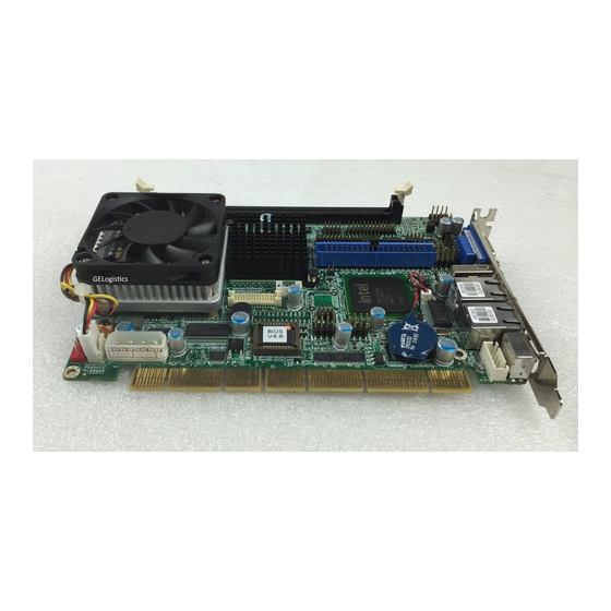
1. Introduction Thanks for choosing PCISA-6770 PENTIUM-M Single Board Computer. The PCISA-6770 board is a PCISA form factor board equipped with high performance processor and multi-mode I/O. It is designed for system manufacturers, integrators, or VARs that want to provide all the performance, reliability, and quality at a reasonable price. -
Page 6: Specifications
Specifications Intel Pentium-M/Celeron-M Processor Supports 400/533(optional) MHz FSB Bus interface PCI/ISA Bus speed ISA: 8MHZ, PCI: 33MHz, DMA channels Interrupt levels Chipset INTEL 852GM (GMCH)/855GME(optional) Real-time clock INTEL 82801DB(ICH4) One 184-pin DIMM socket Support DDR 200/266/333(855GME) System memory SDRAM Maximum memory is up to 1GB Up to four PCI enhanced IDE hard drives Can handle data transfer up to 100MB/s ATA/100... - Page 7 Supports Serial Infrared(SIR) and Amplitude IrDA port Shift Keyed IR(ASKIR) interface Supports 5 USB2.0/1.1 ports for future USB port expansion Software programmable reset generated when CPU does not periodically trigger the timer Watch-dog timer The BIOS INT15 can be used to control the watchdog and generate the system reset i852GM integrated graphic engine VGA controller...
-
Page 8: Package Contents
( *CPU needs cooler & silicone heat sink paste* ) WARNING ! 1. Never run the processor without the heat sink (cooler)properly and firmly attached. Package Contents One PCISA-6770 Single Board Computer One ATA/100 IDE cable One RS-232 and Printer Cable & One RS232/422/485 Cable with bracket One USB cable One Audio cable... -
Page 9: Layout
This chapter describes how to install the PCISA-6770. At first, the layout of PCISA-6770 is shown, and the unpacking information that you should be careful is described. The jumpers and switches setting for the PCISA-6770's configuration are also included. Layout... -
Page 11: Clear Cmos Setup
to static electric charges and can be damaged by a sudden rush of power. To protect it from unintended damage, be sure to follow these precautions: Ground yourself to remove any static charge before touching PCISA-6770 SBC. You can do it by using a grounded wrist strap at all times or by frequently touching any conducting materials that is connected to the ground. -
Page 12: Lvds Voltage Mode Setting
JP2 : Master/Salve Mode Setting DESCRIPTION Master Slave LVDS Voltage Mode Setting JP3 : 3.3V/5V Mode Setting DESCRIPTION 3.3V 3. Connection... - Page 13 This chapter describes how to connect peripherals, switches and indicators to the PCISA-6770 board. Table of Connectors Label Function IDE1 Ultra ATA100 Primary (40 Pin) IDE2 Secondary IDE connectors (44 PIN ) FDD1 Floppy connector LPT1 Parallel port connector DIO1 Digital I/O COM1 Serial port connector(10 Pin)
-
Page 14: Floppy Disk Drive Connector
Floppy Disk Drive Connector The PCISA-6770 board is equipped with a 34-pin daisy- chain drive connector cable. • FDD1 : FDC Connector DESCRIPTI DESCRIPTION GROUND REDUCE WRITE GROUND GROUND INDEX# GROUND MOTOR ENABLE A# GROUND DRIVE SELECT B# GROUND DRIVE SELECT A# GROUND MOTOR ENABLE B# GROUND... -
Page 15: Parallel Port
DATA 4 DATA 11 DATA 3 DATA 12 DATA 2 DATA 13 DATA 1 DATA 14 DATA 0 DATA 15 GROUND GROUND IOW# GROUND IOR# GROUND BALE – DEFAULT GROUND – DEFAULT INTERRUPT IOCS16#-DEFAULT HDC CS0# HDC CS1# HDD ACTIVE# GROUND •... -
Page 16: Serial Ports
6770 includes an on-board parallel port accessed through a 26-pin flat-cable connector. • LPT1 : Parallel Port Connector PIN NO. DESCRIPTION PIN NO. DESCRIPTION STROBE# AUTO FORM FEED # DATA 0 ERROR# DATA 1 INITIALIZE DATA 2 PRINTER SELECT LN# DATA 3 GROUND DATA 4... -
Page 17: Keyboard & Ps/2 Mouse Connector
(13) RS-422 RX+ (14) RS-422 RX- Keyboard & PS/2 Mouse Connector A 6-pin mini DIN connector is located on the mounting bracket for easy connection to a keyboard or a PS/2 mouse. The card comes with a PS/2 Y splitter cables for keyboard and mouse connection. -
Page 18: Ps-On Connector
HDD LED Reset HDD LED + Reset PIN1 Button HDD LED - Reset PIN2 PS-ON Connector • CN4 : Backplane to CPU board Connector PIN NO. DESCRIPTION ATX-ON 5VSB Power source from Backplane with ATX Connector (Through Power Button & +5VSB) USB Port Connector The PCISA-6770 provides 2 built-in USB2.0 ports for the future I/O bus expansion. -
Page 19: Fan Connectors (Fan1)
3.10 Fan Connectors (FAN1) The PCISA-6770 provides two CPU cooling fan connectors, These connectors can supply 12V/500mA to the cooling fan. All connectors have the same pin assignments and provide a "rotation" pin to get rotation signals from fans and notice the system. -
Page 20: Digital I/O Connector
PIN NO. DESCRIPTION GROUND GROUND +12V 3.13 Digital I/O Connector One characteristic of digital circuit is its fast response to high or low signal. This kind of response is highly needed for harsh and critical industrial operating environment. That’s why we design 4- bit digital inputs and 4-bit digital outputs on the PCISA-6770 Digital Input and Output, generally, are control signals. -
Page 21: Lvds1 Connector
CLK- 3.15 LVDS1 CONNECTOR • LVDS1 : LVDS Connector DESCRIPTION DESCRIPTION LVDSB_Y3- LVDSB_CLK+ LVDS_Y3+ LVDSB_CLK- LVDS_Y3- LVDSB_Y2+ LVDS_CLK+ LVDSB_Y2- LVDS_CLK- LVDSB_Y1+ LVDS_Y2+ LVDSB_Y1- LVDS_Y2- LVDSB_Y0+ LVDS_Y1+ LVDSB_Y0- LVDS_Y1- LVDS_Y0+ LVDS_Y0- VCC_LCD VCC_LCD VCC_LCD LVDSB_Y3+ VCC_LCD 3.16 Compact Flash Storage Card Socket (J1) The PCISA-6770 configures Compact Flash Storage Card in IDE Mode. -
Page 22: Backlight Inverter Connector
GROUND IOR# IOW# IRQ15 MASTER/SLAVE RESET# IORDY ACTIVE# PDIAG# PULL DOWN GROUND 3.17 Backlight inverter Connector CN1: backlight inverter connector PIN NO. DESCRIPTION GROUND BKL_POWER GROUND... -
Page 23: Ami Bios Setup
4. AMI BIOS SETUP Introduction This manual discusses AMI's Setup program built into the ROM BIOS. The Setup program allows users to modify the basic system configuration. This special information is then stored in battery-backed RAM so that it retains the Setup information when the power is turned off. -
Page 24: Using Setup
Using Setup In general, you use the arrow keys to highlight items, press <Enter> to select, use the PageUp and PageDown keys to change entries, press <F1> for help and press <Esc> to quit. The following table provides more detail about how to navigate in the Setup program using the keyboard. -
Page 25: Bios Menu Bar
understand. To this end, we strongly recommend that you avoid making any changes to the chipset defaults. These defaults have been carefully chosen by both AMI and your systems manufacturer to provide the absolute maximum performance and reliability. Even a seemingly small change to the chipset setup has the potential for causing you to use the override. -
Page 26: Main
Main When you enter the BIOS Setup program, the Main menu screen appears giving you an overview of the basic system information. AMI BIOS This item displays the auto-detected BIOS information. Processor This item displays the auto-detected CPU specification. System Memory This item displays the auto-detected system memory. -
Page 27: Advanced
Advanced The Advanced menu items allow you to change the settings for the CPU and other system devices... - Page 28 4.7.1 CPU Configuration The items in this menu show the CPU-related information auto- detected by BIOS. Intel® SpeedStep™ tech. [Automatic] This item allows you to Select disable the processor Hyper- Threading Technology. Configuration options: [Maximum Speed] [Minimum Speed] [Automatic] [Disabled]...
- Page 29 4.7.2 IDE Configuration The items in this menu allow you to set or change the configurations for the IDE devices installed in the system. Select an item then press Enter if you wish to configure the item Onboard PCI IDE Controller:[Both] Configuration options: [Disable] [Primary] [Secondary] [Both] Primary and Secondary IDE Master/Slave The values opposite the dimmed items (Device, Vendor, Size,...
- Page 30 LBA/Large Mode [Auto] Enables or disables the LBA mode. Setting to Auto enables the LBA mode if the device supports this mode, and if the device was not previously formatted with LBA mode disabled. Configuration options: [Disabled] [Auto] Block (Multi-sector Transfer) [Auto] Enables or disables data multi-sectors transfers.
- Page 31 4.7.3 Floppy Configuration Sets the type of floppy drive installed. Configuration options: [Disabled][360K, 5.25 in.][1.2M , 5.25 in.][720K , 3.5 in.] [1.44M, 3.5 in.] [2.88M,3.5in.] Floppy Device Swap [Disabled] : Configuration options: [Disabled][Enabled]...
- Page 32 4.7.4 SuperIO Configuration On Board Floppy Controller [Enabled] Allows you to enable or disable the floppy disk controller. Configuration options: [Disabled] [ Enabled] Serial Port1 Address [3F8/IRQ4] Allows you to select the Serial Port1 base address. Configuration options: [Disabled] [3F8/IRQ4] [3E8/IRQ4] [2E8/IRQ3] Serial Port2 Address [2F8/IRQ3] Allows you to select the Serial Port2 base address.
- Page 33 Parallel Port Address [378] Allows you to select the Parallel Port base addresses. Configuration options: [Disabled] [378] [278] [3BC] Parallel Port Mode [Normal] Allows you to select the Parallel Port mode. Configuration options: [Normal] [Bi-directional] [EPP] [ECP] Parallel Port IRQ [IRQ7] Configuration options: [IRQ5] [IRQ7] Digital I/O Function [Enabled] Configuration options: [Disabled] [Enabled]...
- Page 34 4.7.6 ACPI Configuration Allows you to change the settings for the Advanced Power Management (APM). Select an item then press Enter to display the configuration options. ACPI Aware O/S [Yes] Configuration options: [No] [Yes] General ACPI Configuration Allows you to select the ACPI state to be used for system suspend.
- Page 35 4.7.7 Advanced ACPI Configuration ACPI APIC support [Enabled] Configuration options: [Disabled] [Enabled] Apic ACPI SCI IRQ [Disabled] Configuration options: [Disabled] [Enabled] BIOS AML ACPI table [Enabled] --> Configuration options: [Disabled] [Enabled] Headless mode [Disabled] Configuration options: [Disabled] [Enabled]...
- Page 36 4.7.8 Remote Access Configuration Configure Remote Access. Remote Access [Disabled] Configuration options: [Disabled] [Enabled] Serial port number [COM1] Configuration options: [COM1] [COM2] Serial port Mode [115200 8,n,1] Configuration options: [115200 8,n,1] [57600 8,n,1] [38400 8,n,1] [19200 8,n,1] [09600 8,n,1] Flow Control [None] Configuration options: [None] [Hardware] [Software] Redirection After BIOS POST [Always] Configuration options: [Disabled] [Boot Loader] [Always]...
- Page 37 VT-UTF8 Combo Key Support [Disabled] Configuration options: [Disabled] [Enabled] 4.7.9 USB Configuration The items in this menu allows you to change the USB-related features. Select an item then press Enter to display the configuration options. USB Function [5 USB Ports] Allows you to set the number of USB ports to activate.
-
Page 38: Pcipnp
USB 2.0 Controller Mode [HiSpeed] Allows you to configure the USB 2.0 controller in HiSpeed (480 Mbps) or Full Speed (12 Mbps). Configuration options: [HiSpeed ] [Full Speed] PCIPnP The PCI PnP menu items allow you to change the advanced settings for PCI/PnP devices. - Page 39 Configuration options: [32] [64] [96] [128] [160] [192] [224] [248]. Allocate IRQ to PCI VGA [Yes] When set to [Yes], BIOS assigns an IRQ to PCI VGA card if the card requests for an IRQ. When set to [No], BIOS does not assign an IRQ to the PCI VGA card even if requested.
-
Page 40: Boot
Boot The Boot menu items allow you to change the system boot options. Select an item then press Enter to display the sub- menu. 4.9.1 Boot Settings Configuration Quiet Boot [Disabled] This allows you to enable or disable the full screen logo display feature. - Page 41 Allows you to select the power-on state for the NumLock. Configuration options: [Off] [On] PS/2 Mouse Support [Auto] Allows you to enable or disable support for PS/2 mouse. Configuration options: [Disabled] [Enabled] [Auto] Wait for ‘F1’ If Error [Enabled] When set to Enabled, the system waits for F1 key to be pressed when error occurs.
-
Page 42: Security
4.10 Security The Security menu items allow you to change the system security settings. Select an item then press Enter to display the configuration options. Change Supervisor Password Select this item to set or change the supervisor password. The Supervisor Password item on top of the screen shows the default Not Installed. -
Page 43: Chipset
Configuration options: [Disabled] [Enabled] 4.11 Chipset The Chipset menu items allow you to change the advanced chipset settings. Select an item then press Enter to display the sub-menu. 4.11.1 NorthBridge Configuration Configure DRAM Timing by SPD [Enabled] When this item is enabled, the DRAM timing parameters are set according to the DRAM SPD (Serial Presence Detect). - Page 44 boot device. Configuration options: [Internal VGA] [AGP/Int-VGA] [AGP/PCI] [PCI/AGP] [PCI/Int-VGA] Internal Graphics Mode Select [Enable, 8MB] Select the amount of system memory used by the internal graphics device. Configuration options: [Enable, 1MB] [Enable, 4MB] [Enable, 8MB] [Enable, 16MB] [Enable, 32MB] Graphics Aperture Size [64MB] Allows you to select the size of mapped memory for AGP graphic data.
-
Page 45: Power
4.12 Power Power Management/APM [Enabled] Allows you to enable or disable the Advanced Power Management (APM) feature. Configuration options: [Disabled] [Enabled] Power Type Select [ATX] Allows you to select the power type mode. Configuration options: [ATX] [AT] Video Power Down Mode [Suspend] Allows you to select the video power down mode. - Page 46 Configuration options:[Disabled] [1 Min] [2 Min] [4 Min] [8 Min] [10 Min] [20 Min] [30 Min] [40 Min] [50 Min] [60 Min] Suspend Time Out [Disabled] Allows you to select the specified time at which the system goes on suspend. Configuration options:[Disabled] [1 Min] [2 Min] [4 Min] [8 Min] [10 Min] [20 Min] [30 Min] [40 Min] [50 Min] [60 Min] Throttle Slow Clock Ratio [50%]...
-
Page 47: Exit
When this item is set to Enabled, the items RTC Alarm Date, RTC Alarm Hour, RTC Alarm Minute, and RTC Alarm Second appear with set values. Configuration options: [Disabled] [Enabled] 4.13 Exit The Exit menu items allow you to load the optimal or failsafe default values for the BIOS items, and save or discard your changes to the BIOS items. - Page 48 that you made to the Setup program. If you made changes to fields other than system date, system time, and password, the BIOS asks for a confirmation before exiting. Discard Changes This option allows you to discard the selections you made and restore the previously saved values.
-
Page 49: Appendix A. Watchdog Timer
Appendix A. WatchDog Timer The WatchDog Timer is provided to ensure that standalone systems can always recover from catastrophic conditions that cause the CPU to crash. This condition may have occurred by external EMI or a software bug. When the CPU stops working correctly, hardware on the board will either perform a hardware reset (cold boot) or a Non-Maskable Interrupt (NMI) to bring the system back to a known state. - Page 50 Note: when exiting a program it is necessary to disable the WatchDog Timer, otherwise the system will reset. Example program: ; INITIAL TIMER PERIOD COUNTER W_LOOP: AX, 6F02H ;setting the time-out value BL, 30 ;time-out value is 48 seconds ; ADD YOUR APPLICATION PROGRAM HERE EXIT_AP, 1 ;is your application over? W_LOOP...
-
Page 51: Appendix B: Digital I/O
Appendix B: Digital I/O One characteristic of digital circuit is its fast response to high or low signal. This kind of response is highly needed for harsh and critical industrial operating environment. That’s why we design 4-bit digital inputs and 4-bit digital outputs on the PCISA-6770. Digital Input and Output, generally, are control signals. - Page 52 Digital Output is 1001b...
-
Page 53: Appendix C. Resources Map
Appendix C. Resources Map 1 st MB Memory Address Map Memory address Description 00000-9FFFF SYSTEM MEMORY A0000-BFFFF VGA BUFFER C0000-CFFFF VGA BIOS E0000-FFFFF SYSTEM BIOS 100000 EXTEND MEMORY IRQ Mapping Chart IRQ0 System Timer IRQ8 RTC clock IRQ1 Keyboard IRQ9 SCI IRQ user by ACPI bus IRQ2 IRQ Controller...
Need help?
Do you have a question about the PCISA-6770 Series and is the answer not in the manual?
Questions and answers