Sign In
Upload
Manuals
Brands
IEI Technology Manuals
Single board computers
AESQ170-969
IEI Technology AESQ170-969 Manuals
Manuals and User Guides for IEI Technology AESQ170-969. We have
1
IEI Technology AESQ170-969 manual available for free PDF download: User Manual
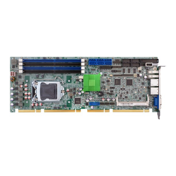
IEI Technology AESQ170-969 User Manual (121 pages)
Brand:
IEI Technology
| Category:
Single board computers
| Size: 5.39 MB
Table of Contents
Table of Contents
2
List of Figures
5
List of Tables
7
BIOS Menus
9
Copyright
10
Copyright Notice
10
Revision
10
Trademarks
10
Manual Conventions
11
Chapter 1 Introduction
12
Introduction
12
Model Variations
12
Figure 1-1: AESQ170-969 Series
12
Features
13
Connectors
13
Table 1-1: AESQ170-969 Model Variations
13
Dimensions
14
Figure 1-2: Connectors
14
Figure 1-3: AESQ170-969 Dimensions (MM)
15
Data Flow
16
Figure 1-4: Data Flow Diagram
16
Technical Specifications
17
Table 1-2: AESQ170-969 Specifications
19
Chapter 2 Packing List
20
Anti-Static Precautions
20
Unpacking Precautions
20
Packing List
20
Optional Items
21
Table 2-1: Packing List
21
Table 2-2: Optional Items
24
Chapter 3 Connectors
25
Peripheral Interface Connectors
25
AESQ170-969 Layout
25
Figure 3-1: Peripheral Interface Connectors
25
External Interface Panel Connectors
27
Internal Peripheral Connectors
27
ATX Power Connector
27
Figure 3-2: +12V ATX Power Connector Pinout Location
27
Table 3-1: Peripheral Interface Connectors
27
Table 3-2: External Peripheral Connectors
27
Audio Kit Connector
28
Battery Connector
28
Figure 3-3: Audio Connector Location
28
Table 3-3: +12V ATX Power Connector Pinouts
28
Table 3-4: Audio Connector Pinouts
28
Chassis Intrusion Connector
29
Figure 3-4: Battery Connector Location
29
Figure 3-5: Chassis Intrusion Connector Location
29
Table 3-5: Battery Connector Pinouts
29
CRT FW Update Connector
30
DDR4 DIMM Sockets
30
Figure 3-6: CRT FW Update Connector Location
30
Table 3-6: Chassis Intrusion Connector Pinouts
30
Table 3-7: CRT FW Update Connector Pinouts
30
Digital I/O Connector
31
EC Debug Connector
31
Figure 3-7: DDR4 DIMM Socket Locations
31
Figure 3-8: Digital I/O Connector Location
31
Table 3-8: Digital I/O Connector Pinouts
31
Fan Connector (CPU)
32
Figure 3-9: EC Debug Connector Location
32
Table 3-9: EC Debug Connector Pinouts
32
Fan Connectors (System)
33
Figure 3-10: CPU Fan Connector Location
33
Figure 3-11: System Fan Connector Location
33
Table 3-10: CPU Fan Connector Pinouts
33
Table 3-11: System Fan (SYS_FAN1) Connector Pinouts
33
Front Panel Connector
34
I 2 C Connector
34
Figure 3-12: Front Panel Connector Location
34
Table 3-12: Front Panel Connector Pinouts
34
Internal Displayport Connector
35
Figure 3-13: I C Connector Location
35
Figure 3-14: Internal Displayport Connector Location
35
Table 3-13: I 2 C Connector Pinouts
35
Iris-2400 Module Slot (AESQ170-969-I2-R10 Only)
36
Keyboard and Mouse Connector
36
Figure 3-15: Iris-2400 Module Slot Location
36
Table 3-14: Internal Displayport Connector Pinouts
36
LAN LED Connectors
37
Figure 3-16: Keyboard and Mouse Connector Location
37
Figure 3-17: LAN LED Connector Locations
37
Table 3-15: Keyboard and Mouse Connector Pinouts
37
Parallel Port Connector
38
Figure 3-18: Parallel Port Connector Location
38
Table 3-16: LAN1 LED Connector (LED_LAN1) Pinouts
38
Table 3-17: LAN2 LED Connector (LED_LAN2) Pinouts
38
Pcie Mini Slot
39
Figure 3-19: Pcie Mini Slot Location
39
Table 3-18: Parallel Port Connector Pinouts
39
Power Button
40
Table 3-19: Pcie Mini Slot Pinouts
40
Serial Port Connectors
41
RS-232/422/485 Serial Port Connectors
41
Figure 3-20: Power Button Location
41
Figure 3-21: RS-232 Serial Port Connector Locations
41
Table 3-20: RS-232 Serial Port Connector Pinouts
41
Figure 3-22: RS-232/422/485 Serial Port Connector Locations
42
Table 3-21: RS-232/422/485 Serial Port Connector Pinouts
42
SATA 6Gb/S Drive Connector
43
Figure 3-23: SATA 6Gb/S Drive Connector Locations
43
Table 3-22: DB-9 RS-232/422/485 Pinouts
43
Table 3-23: SATA 6Gb/S Drive Connector Pinouts
43
Smbus Connector
44
SPI Flash Connector
44
Figure 3-24: Smbus Connector Location
44
Table 3-24: Smbus Connector Pinouts
44
SPI Flash Connector, EC
45
Figure 3-25: SPI Flash Connector Location
45
Figure 3-26: SPI EC Flash Connector Location
45
Table 3-25: SPI Flash Connector Pinouts
45
TPM Connector
46
Figure 3-27: TPM Connector Location
46
Table 3-26: SPI EC Flash Connector Pinouts
46
Table 3-27: TPM Connector Pinouts
46
USB 2.0 Connectors
47
USB 2.0 Connector (Type A)
47
Figure 3-28: USB 2.0 Connector Locations
47
Figure 3-29: USB 2.0 Connector (Type A) Pinout Location
47
Table 3-28: USB 2.0 Connector Pinouts
47
USB 3.1 Gen 1 Connector
48
Figure 3-30: USB 3.1 Gen 1 Connector Location
48
Table 3-29: USB 2.0 Connector (Type A) Pinouts
48
External Peripheral Interface Connector Panel
49
Ethernet Connectors
49
Figure 3-31: External Peripheral Interface Connector
49
Table 3-30: USB 3.1 Gen 1 Connector Pinouts
49
Table 3-31: LAN Pinouts
49
USB 3.1 Gen 1 Connectors
50
VGA Connector
50
Figure 3-32: Ethernet Connector
50
Table 3-32: USB 3.1 Gen 1 Port Pinouts
50
Figure 3-33: VGA Connector
51
Table 3-33: VGA Connector Pinouts
51
Chapter 4 Installation
52
Anti-Static Precautions
52
Installation Considerations
52
Socket LGA1151 CPU Installation
53
Figure 4-1: Disengage the CPU Socket Load Lever
54
Figure 4-2: Remove Protective Cover
55
Figure 4-3: Insert the Socket LGA1151 CPU
56
Figure 4-4: Close the Socket LGA1151
56
Socket LGA1151 Cooling Kit Installation
57
Figure 4-5: Cooling Kit Support Bracket
57
DIMM Installation
58
Figure 4-6: DIMM Installation
58
Iris-2400 Module Installation (Optional)
59
Figure 4-7: Iris-2400 Module Installation
59
Full-Size Pcie Mini Card Installation
60
Figure 4-8: Removing the Retention Screw
60
Figure 4-9: Inserting the Full-Size Pcie Mini Card into the Slot at an Angle
61
Figure 4-10: Securing the Full-Size Pcie Mini Card
61
Half-Size Pcie Mini Card Installation
62
Figure 4-11: Installing the Standoff
62
Figure 4-12: Inserting the Half-Size Pcie Mini Card into the Slot at an Angle
63
Figure 4-13: Securing the Half-Size Pcie Mini Card
63
System Configuration
64
AT/ATX Power Mode Setting
64
Clear CMOS Button
64
Pcie X4 Channel Mode Setup
64
Figure 4-14: AT/ATX Power Mode Switch Location
64
Figure 4-15: Clear CMOS Button Location
64
Table 4-1: AT/ATX Power Mode Switch Settings
64
Pcie X16 Channel Mode Setup
65
Figure 4-16: BIOS Switch Location
65
Table 4-2: BIOS Switch Settings
65
Flash Descriptor Security Override Jumper
66
Figure 4-17: Flash Descriptor Security Override Jumper Location
66
Table 4-3: Pcie X16 Channel Mode Setup
66
Table 4-4: Flash Descriptor Security Override Jumper Settings
66
USB Power Selection
67
Msata Setup
67
Table 4-5: BIOS Options and Configured USB Ports
67
Table 4-6: USB Power Source Setup
67
Table 4-7: Msata Setup Jumper Settings
67
Internal Peripheral Device Connections
68
Figure 4-18: Msata Setup Jumper Location
68
Figure 4-19: SATA Drive Cable Connection
69
Adding USB 3.1 Gen 1 Drivers to a Windows 7 Installation Image
70
Figure 4-20: SATA Power Drive Connection
70
Figure 4-21: Windows 7 USB 3.0 Creator Utility
71
Intel ® AMT Setup Procedure
72
Figure 4-22: Update Process Is Complete
72
IPMI Setup Procedure (AESQ170-969-I2-R10 Only)
73
Chapter 5 BIOS
74
Introduction
74
Main
75
Table 5-1: BIOS Navigation Keys
75
Advanced
77
Trusted Computing
77
ACPI Settings
78
AMT Configuration
79
Super IO Configuration
80
Iwdd H/W Monitor
85
RTC Wake Settings
86
Serial Port Console Redirection
87
CPU Configuration
90
SATA Configuration
92
Nvme Configuration
93
USB Configuration
93
Chipset
94
System Agent (SA) Configuration
95
PCH-IO Configuration
98
Table 5-2: BIOS Options and Configured USB Ports
100
Security
103
Boot
103
Save & Exit
105
Server Mgmt (AESQ170-969-I2-R10 Only)
106
System Event Log
106
BMC Network Configuration
107
Appendix A Regulatory Compliance
109
Declaration of Conformity
109
Fcc Warning
109
Appendix B Product Disposal
110
Appendix C BIOS Options
111
Appendix D Terminology
113
Appendix E Digital I/O Interface
116
Introduction
116
Assembly Language Sample 1
116
Assembly Language Sample 2
116
Appendix F Watchdog Timer
118
Table F-1: AH-6FH Sub-Function
118
Example Program
119
Appendix G Hazardous Materials Disclosure
120
Advertisement
Advertisement
Related Products
IEI Technology AFL-08AH-N270-CR
IEI Technology AFL3-W15A-BT
IEI Technology AFL3-W22C-ULT5-P-PC-4G
IEI Technology AFL2-17A-H61-P/R-R13
IEI Technology AFL2-W19A-H61-P/PC-R11
IEI Technology AFL-12A-N270/R/1G-R21
IEI Technology AFL3-W07A-AL2
IEI Technology AFL3-W15C-ADLP-i7/8G-R10
IEI Technology AFL4-W13-EHL
IEI Technology AFL3PK-W15A-R10
IEI Technology Categories
Motherboard
Touch Panel
Computer Hardware
Single board computers
Desktop
More IEI Technology Manuals
Login
Sign In
OR
Sign in with Facebook
Sign in with Google
Upload manual
Upload from disk
Upload from URL