Advertisement
Quick Links
EPIC SBC with Intel® Atom™ N270 1.6GHz, VGA/Dual LVDS,
Quick Installation Guide
Package Contents
NANO-945GSE package includes the following items:
1 x NANO-945GSE Single Board Computer
1 x KB/MS cable
2 x SATA cable
1 x Power cable
2 x RS-232 cable
1 x Mini Jumper Pack
1 x Utility CD
1 x QIG (Quick Installation Guide)
Dual GbE, CF II, USB, SATA
NANO-945GSE
Version 2.0
Aug. 03, 2011
©2006 Copyright by IEI Technology corp.
All rights reserved.
1
Advertisement

Related Manuals for IEI Technology NANO-945GSE


Summary of Contents for IEI Technology NANO-945GSE
- Page 1 Dual GbE, CF II, USB, SATA NANO-945GSE Quick Installation Guide Version 2.0 Aug. 03, 2011 Package Contents NANO-945GSE package includes the following items: 1 x NANO-945GSE Single Board Computer 1 x KB/MS cable 2 x SATA cable 1 x Power cable 2 x RS-232 cable...
- Page 2 Specifications CPU: On board Intel® Atom™ N270 1.6GHz/512KB L2 Cache FSB 533MHz System Chipset: Intel® 945GSE +ICH7M BIOS: AMI BIOS System memory: 1 x 200-pins 533/400MHz DDR2 SDRAM SO-DIMM (max. 2GB) Ethernet: Dual Realtek RTL8111E GbE Controllers I/O Interface: 2 x SATA 6 x USB 2.0 (4 by header, 2 on rear side) 1 x CF Type II 3 x RS-232...
-
Page 3: Ordering Information
Temperature: 0 ~ 60°C(32 ~ 140°F) Dimension: 165 mm x 115 mm Weight: GW: 1100g; NW: 250g Ordering Information NANO-945GSE-N270-R20: EPIC SBC with Intel® Atom™ N270 1.6G, VGA/LVDS, Dual GbE,CFII, USB, SATA NANO-945GSE-N270W-R20: EPIC SBC with Intel® Atom™ N270 1.6G, VGA/LVDS, Dual GbE,CFII, USB,... -
Page 4: Jumpers Setting
Jumpers setting LABEL FUNCTION J_CMOS1 CMOS state setting COM2 Port Mode setting J_VLVDS1 LVDS1 Voltage Selection J_VLVDS2 LVDS2 Voltage Selection PCI-104 VIO Selector JCF1 CF Card setting ATXCTL1 AT Power Mode Setting J_LCD_TYPE1 LVDS1 & LVDS2 Panel Resolution Selection... - Page 5 JP1: configure COM2 Mode J_CMOS1: Clear CMOS Setup DESCRIPTION J_CMOS1 DESCRIPTION Short 1-2 RS - 232 (default) Short 1-2 Keep CMOS Setup (default)* (Normal Operation) Short 3-4 RS - 422 Short 2-3 Clear CMOS Setup Short 5-6 RS - 485 J_VLVDS1: LVDS1 Voltage Selection J_VLVDS2: LVDS 2 Voltage Selection J_VLVDS1...
- Page 6 Table of Connectors LABEL FUNCTION VGA1 VGA 15-pin Female Connector USB_C45 2 Port USB Connector LAN1 RJ45 LAN Connectors LAN2 KB_MS1 PS/2 MOUSE & KEYBOARD Connectors COM1 COM Port Connector Internal Serial Port Connectors COM2 (RS-232/422/485) COM3 Internal Serial Port Connectors (RS-232) COM4 LPT1 Parallel Port Connector...
- Page 7 VGA1: 15-pin Female Connector PIN NO. DESCRIPTION PIN NO. DESCRIPTION GREEN BLUE CRT_PLUG# DDCDAT HSYNC VSYNC DDCCLK USB_C45: USB Connector PIN NO. DESCRIPTION PIN NO. DESCRIPTION VCC (+5V) VCC (+5V) DATA4- DATA5- DATA4+ DATA5+ GROUND GROUND LAN1、LAN2: RJ45 LAN Connector PIN NO.
-
Page 8: Transmit Data
COM1: Serial Port Connector PIN NO. DESCRIPTION DATA CARRIER DETECT (DCD#) RECEIVE DATA (RXD) TRANSMIT DATA (TXD) DATA TERMINAL READY (DTR#) (GND) DATA SET READY (DSR#) REQUEST TO SEND (RTS#) CLEAR TO SEND (CTS#) RING INDICATOR (RI#) COM2 : Internal Serial Port Connector PIN NO. - Page 9 LPT1 : Parallel Port Connector PIN NO. DESCRIPTION PIN NO. DESCRIPTION STROBE# AUTO FORM FEED # DATA0 ERROR# DATA1 INITIALIZE# DATA2 PRINTER SELECT LN# DATA3 DATA4 DATA5 DATA6 DATA7 ACKNOWLEDGE# BUSY PAPER EMPTY PRINTER SELECT USB01, USB23: Internal USB Connector PIN NO.
- Page 10 IDE1 : IDE Interface Connector PIN NO. DESCRIPTION PIN NO. DESCRIPTION RESET# DATA 7 DATA 8 DATA 6 DATA 9 DATA 5 DATA 10 DATA 4 DATA 11 DATA 3 DATA 12 DATA 2 DATA 13 DATA 1 DATA 14 DATA 0 DATA 15 IDE DRQ...
- Page 11 LVDS1: LVDS Connector (18-bit) PIN NO. DESCRIPTION PIN NO. DESCRIPTION GND1 GND2 A_Y0 A_Y0# A_Y1 A_Y1# A_Y2 A_Y2# A_CK A_CK# GND3 GND4 B_Y0 B_Y0# B_Y1 B_Y1# B_Y2 B_Y2# B_CK B_CK# GND5 GND6 VCC_LCD VCC_LCD VCC_LCD VCC_LCD LVDS2: LVDS Connector (18/24-bit) PIN NO.
- Page 12 F_PANEL1 : PWR & RST Buttons and Indicators panel PIN DESCRIPTION PIN DESCRIPTION PWRBTSW- Power PWRBTN GROUND GROUND SYSRST- RESET -HDLED Ground ATXCTL1 : ATX Power Control Connector PIN NO. DESCRIPTION PS_ON# 5VSB CN1: +12V MAIN POWER Input Connector PIN NO. DESCRIPTION PIN NO.
- Page 13 CF1 : CF Card Interface Slot PIN NO. DESCRIPTION PIN NO. DESCRIPTION CD1# CE2# VS1# IOR# IOW# CSEL# VS2# RESET# WAIT# INPACK# REG# BVD2 BVD1 IOCS16# CD2# GND2...
- Page 14 PC104_PLUS1: PC/104-Plus Connector (120-pin PCI bus) PIN Description PIN Description PIN Description PIN Description B1 RESERVED1 C1 VIO1 CBE0- AD11 VIO2 AD10 M66EN AD14 AD13 AD12 CBE1- AD15 SERR- SBO- PERR- SDONE STOP- LOCK- TRDY- D12 DEVSEL- FRAME- IRDY- AD16 CBE2- AD18 AD17...
- Page 15 CN4: PCI-E Mini Card Connector PIN NO. DESCRIPTION PIN NO. DESCRIPTION PCIE_WAKE# VCC3 1.5V CLKREQ# LFRAME# LAD3 CLK- LAD2 CLK+ LAD1 LAD0 PCIRST# VCC3 PCIRST# PERN2 3VDual PERP2 1.5V SMBCLK PETN2 SMBDATA PETP2 USBD- USBD+ RF_LINK# BLUELED# 1.5V VCC3...
-
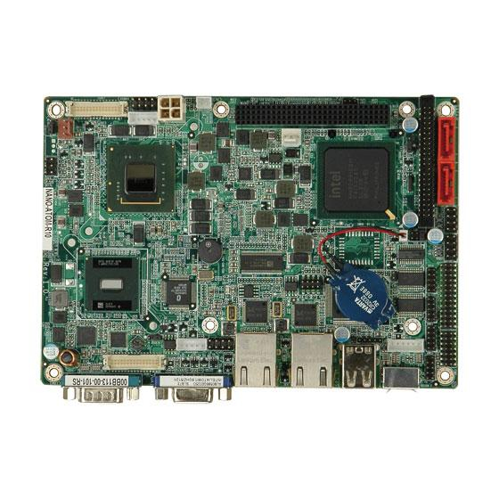
Page 16: Board Layout: Jumper And Connector Locations
Board Layout: Jumper and Connector Locations...
Need help?
Do you have a question about the NANO-945GSE and is the answer not in the manual?
Questions and answers