Advertisement
Quick Links
3.5" SBC with Intel® Atom™ N270 1.6GHz Processor,
VGA/LVDS/TTL, PCIe GbE, CFII, USB, SATA, 4 COM and
Quick Installation Guide
Package Contents
WAFER-945GSE3 package includes the following items:
l
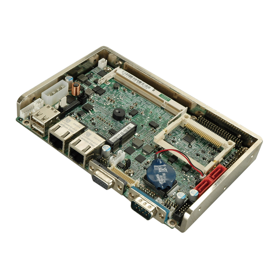
1 x WAFER-945GSE3 Single Board Computer
l
2 x SATA Cable
l
1 x PS/2 KB/MS Y Cable
l
1 x Audio Cable
l
1 x Dual Ports USB Cable
l
2 x RS-232 Cable
l
1 x Mini Jumper Pack
l
1 x Utility CD
l
1 x QIG (Quick Installation Guide)
WAFER-945GSE3
Version 1.0
Jul. 22, 2010
©200 6 Copyright by IEI Technology corp.
All rights reserved.
PC/104
1
Advertisement

Related Manuals for IEI Technology WAFER-945GSE3


Summary of Contents for IEI Technology WAFER-945GSE3
- Page 1 WAFER-945GSE3 Quick Installation Guide Version 1.0 Jul. 22, 2010 Package Contents WAFER-945GSE3 package includes the following items: 1 x WAFER-945GSE3 Single Board Computer 2 x SATA Cable 1 x PS/2 KB/MS Y Cable 1 x Audio Cable 1 x Dual Ports USB Cable...
-
Page 2: Power Supply
Specifications l CPU: Intel® Atom™ Processor N270 1.6GHz/512KB L2 Cache with a 533MHz FSB l System Chipset: Intel® 945GSE +ICH7M l BIOS: AMI BIOS, SPI 8Mbit Flash ROM l System memory: 1 x 200-pins 533/400MHz DDR2 SDRAM SO-DIMM (max. 2GB) l Ethernet: One Realtek RTL8111CP (PCIe x1 Interface) GbE Controller l I/O Interface:... - Page 3 Operating Temperature: 0 ~ 60°C(32 ~ 140°F) l Dimension: 146 mm x 102 mm l Weight: GW: 650g; NW: 250g Ordering Information WAFER-945GSE3-N270-R10: 3.5" SBC with Intel® Atom™ N270 1.6GHz Processor, VGA/LVDS/TTL, PCIe GbE, CFII, USB, SATA, 4 COM and PC/104 32200-015100-RS: LPT cable...
- Page 4 J_VLVDS1: LVDS Voltage Selection J_VLVDS1 DESCRIPTION +3.3V LVDS +5V LVDS JCF1: Configure CF Card type JCF1 DESCRIPTION Open Slave (default) Short 1-2 Master ATXCTL1 : AT Power Mode Setting AT Mode: Short 2-3 (Default) ATX Mode: Use PS_ON & 5VSB cable ATXCTL1 DESCRIPTION...
- Page 5 Table of Connectors LABEL FUNCTION LAN1 RJ-45 LAN Connector KB_MS1 Keyboard & Mouse Connector COM1 External Serial Port Connector (RS-232) BAT1 +3V Battery Connector COM2 Internal Serial Port Connector (RS-232/422/485) PWRLED, HDDLED and +5V Power Indicators, LED_C1 output DIO1 Digital I/O Connector COM3, COM4 Internal Serial Port Connectors (RS -232) USB01 Internal 4 Ports USB Connectors...
- Page 6 LAN1: RJ-45 LAN Connector PIN NO. DESCRIPTION PIN NO. DESCRIPTION MDIA3- MDIA1+ MDIA3+ MDIA2+- MDIA2- MDIA0- MDIA1- MDIA0+ KB_MS1: 6-pin Keyboard/Mouse Connector PIN NO. DESCRIPTION KBDATA MSDATA VCC (+5V) KBCLK MSCLK COM1: External Serial Port Connector (RS-232) PIN NO. DESCRIPTION DATA CARRIER DETECT (DCD#) RECEIVE DATA...
- Page 7 COM2 : Internal Serial Port Connector (RS-232/422/485) PIN NO. DESCRIPTION PIN NO. DESCRIPTION DATA CARRIER DATA SET READY DETECT (DCD#) (DSR#) RECEIVE DATA REQUEST TO SEND (RXD) (RTS #) TRANSMIT DATA CLEAR TO SEND (TXD) (CTS #) DATA TERMINAL RING INDICATOR READY (DTR#) (RI#) TXD485+...
- Page 8 USB01, USB23: Internal USB Connectors PIN NO. DESCRIPTION PIN NO. DESCRIPTION VCC (+5V) VCC (+5V) DATA- DATA- DATA+ DATA+ N/A (KEY) AUDIO1 : Audio Connector PIN NO. DESCRIPTION PIN NO. DESCRIPTION LINE_OUTR LINEIN_R LINE_OUTL LINEIN_L MICIN MICIN SATA1 & SATA2 : Serial ATA Connectors PIN NO.
- Page 9 LVDS1: LVDS Connector PIN NO. DESCRIPTION PIN NO. DESCRIPTION A_Y0 A_Y0# A_Y1 A_Y1# A_Y2 A_Y2# A_CK A_CK# B_Y0 B_Y0# B_Y1 B_Y1# B_Y2 B_Y2# B_CK B_CK# VCC_LCD VCC_LCD VCC_LCD VCC_LCD INVERTER1: LVDS Panel Backlight +12V Power Source PIN NO. DESCRIPTION LCD_BKLTCTL +12V BACKLIGHT ENABLE PWRBTN1: Power Button...
- Page 10 CF1 : CF Card Interface Slot PIN NO. DESCRIPTION PIN NO. DESCRIPTION CD1# CE2# VS1# IOR# IOW# CSEL# VS2# RESET# WAIT# INPACK# REG# BVD2 BVD1 IOCS16# CD2# GND2 JSPI1 : SPI flash Connector PIN NO. DESCRIPTION PIN NO. DESCRIPTION SPI_VCC (+3.3V) SPI_CS# SPI_CLK SPI_MISO...
- Page 11 IR1: Infrared interface connector PIN NO. DESCRIPTION VCC (+5V) IR-RX IR-TX TTL1: TTL LCD Connector Description Description LCD_VCC LCD_VCC LCD_VCC LCD_VCC VSYNC HSYNC LCD_EN FAN1: FAN Connector PIN NO. DESCRIPTION FANIO1 +12V...
- Page 12 CN2: PC/104 (64 pin ISA bus) Connector PIN Description PIN Description PIN Description PIN Description -IOCHK SA14 -DACK1 SA13 RSTDRV DRQ1 SA12 B19 -REFRESH SA11 IRQ9 BCLK SA10 IRQ7 DRQ2 IRQ6 IRQ5 -NOWS IRQ4 +12V IRQ3 A10 IOCHRDY A26 -DACK2 B11 -SMEMW SA19 -SMEMR...
- Page 13 SDVO1 : SDVO Connector (Optional) PIN NO. DESCRIPTION PIN NO. DESCRIPTION SDVOB_BLUE- SDVOB_BLUE+ SDVOB_RED- SDVOB_RED+ SDVOB_CLK - SDVO_STALL- SDVOB_CLK+ SDVO_STALL+ SDVOB_GREEN- SDVO_TVCLKIN- SDVOB_GREEN+ SDVO_TVCLKIN+ SDVO_CLK SDVO_DATA PCIRST- SDVOB_INT- SDVOB_INT+ DBG_PORT1 : FirmWare Hub Debug Port Connector (Optional) PIN NO. DESCRIPTION PIN NO.
- Page 14 LPT1: LPT port connector Description Description STB# AFD# ERR# INIT# SLIN# ACK# BUSY SCLT VGA1: VGA 15-pin Female Connector PIN NO. DESCRIPTION PIN NO. DESCRIPTION GREEN BLUE CRT_PLUG# VCC (+5V) DDCDAT HSYNC VSYNC DDCCLK...
- Page 15 Board Layout: Jumper and Connector Locations...
- Page 16 Board dimensions with Heat Sink:...
Need help?
Do you have a question about the WAFER-945GSE3 and is the answer not in the manual?
Questions and answers