Table of Contents
Advertisement
Quick Links
Advertisement
Table of Contents

Related Manuals for AGFA DR 400


Summary of Contents for AGFA DR 400
- Page 1 DR 400 (Radiographic wall stand) 5520/150 User Manual 3256C EN 20221124 1627...
-
Page 2: Table Of Contents
| DR 400 (Radiographic wall stand) | Contents Contents Legal Notice ................4 Introduction to this Manual ........... 5 Scope of this Manual ..........6 About the safety notices in this document ....7 Disclaimer ..............8 Introduction ................9 Intended Use ............10... - Page 3 DR 400 (Radiographic wall stand) | Contents | iii Loading of the bucky in the Radiographic Wall Stand Unloading of the bucky in the Radiographic Wall Stand ..................52 Cassette and detector formats ........53 Standard cassette formats ........54 DR Detector formats and orientation .......
-
Page 4: Legal Notice
Agfa and the Agfa rhombus are trademarks of Agfa-Gevaert N.V., Belgium or its affiliates. DR 400 is a trademark of Agfa NV, Belgium or one of its affiliates. All other trademarks are held by their respective owners and are used in an editorial fashion with no intention of infringement. -
Page 5: Introduction To This Manual
DR 400 (Radiographic wall stand) | Introduction to this Manual | 5 Introduction to this Manual Topics: • Scope of this Manual • About the safety notices in this document • Disclaimer 3256C EN 20221124 1627... -
Page 6: Scope Of This Manual
6 | DR 400 (Radiographic wall stand) | Introduction to this Manual Scope of this Manual This User Manual describes the features of the DR 400 wall stand, further referred to as the radiographic wall stand, that is a variant of the DR 800 system. -
Page 7: About The Safety Notices In This Document
DR 400 (Radiographic wall stand) | Introduction to this Manual | 7 About the safety notices in this document The following samples show how warnings, cautions, instructions and notes appear in this document. The text explains their intended use. DANGER:... -
Page 8: Disclaimer
8 | DR 400 (Radiographic wall stand) | Introduction to this Manual Disclaimer Agfa assumes no liability for use of this document if any unauthorized changes to the content or format have been made. Every care has been taken to ensure the accuracy of the information in this document. -
Page 9: Introduction
DR 400 (Radiographic wall stand) | Introduction | 9 Introduction Topics: • Intended Use • Intended User • Radiographic wall stand • Applied Parts • Installation • Radiation Protection • Labels • Cleaning and Disinfecting • Maintenance • Environmental protection... -
Page 10: Intended Use
10 | DR 400 (Radiographic wall stand) | Introduction Intended Use • The DR 400 system is a General Radiography X-ray imaging system used in hospitals, clinics and medical practices by physicists, radiographers and radiologists to make, process and view static X-ray radiographic images of the skeleton (including skull, spinal column and extremities), chest, abdomen and other body parts on adult or pediatric patients. -
Page 11: Intended User
DR 400 (Radiographic wall stand) | Introduction | 11 Intended User This manual has been written for trained users of Agfa products and trained diagnostic X–Ray clinical personnel who have received proper training. Users are those persons who actually handle the equipment and those who have authority over the equipment. -
Page 12: Radiographic Wall Stand
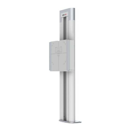
12 | DR 400 (Radiographic wall stand) | Introduction Radiographic wall stand The radiographic wall stand is used for positioning of patients standing upright or sitting towards the bucky for exposure. Figure 1: Radiographic wall stand with vertical bucky Related Links... -
Page 13: Applied Parts
DR 400 (Radiographic wall stand) | Introduction | 13 Applied Parts Applied Parts refer to parts of the medical electrical equipment that in normal use necessarily comes into physical contact with the patient for the equipment to perform its function. This system includes the following Applied Parts: Radiographic wall stand •... -
Page 14: Installation
14 | DR 400 (Radiographic wall stand) | Introduction Installation Installation and configuration is performed by an Agfa trained and authorized service engineer. Contact your local support organization for more information. 3256C EN 20221124 1627... -
Page 15: Radiation Protection
DR 400 (Radiographic wall stand) | Introduction | 15 Radiation Protection X-ray radiation can cause serious damage to the health, therefore observe great care and ensure that protection against X-ray exposure is always applied. Some of the effects of X-ray radiation are cumulative and may extend over a period of time. -
Page 16: Monitoring Of Personnel
16 | DR 400 (Radiographic wall stand) | Introduction Monitoring of Personnel The monitoring checks the amount of X-ray radiation the personnel has been exposed to. It determines safety of the operators and it helps checking if safety measures of the X-ray environment are adequate. Inadequate or improper protection can lead to serious damage to the health. -
Page 17: Protected Area And Significant Zones Of Occupancy
DR 400 (Radiographic wall stand) | Introduction | 17 Protected area and significant zones of occupancy If the operator or staff does not need to be close to the patient during the exposure, the operator and staff use the protected area to control the following functions: •... - Page 18 18 | DR 400 (Radiographic wall stand) | Introduction and intensity of the X-ray exposure, the material of the object and the distance to the object. WARNING: The patient and the operator must wear appropriate radiation protection garments. Significant zones of occupancy at the radiographic wall stand...
- Page 19 DR 400 (Radiographic wall stand) | Introduction | 19 Protective device Wall DR Detector or cassette Significant zone of occupancy at the right side of the radiographic wall stand Significant zone of occupancy at the left side of the radiographic wall...
-
Page 20: Labels
20 | DR 400 (Radiographic wall stand) | Introduction Labels Mark Meaning This mark shows compliance of the equipment with Regulation 2017/745 (for European Union). Type B applied part Date of manufacture Country of origin. The two character code on the actual label contains the country code defined in ISO 3166-1. - Page 21 DR 400 (Radiographic wall stand) | Introduction | 21 Label Meaning Ionizing radiation Pinch Points. Risk of stumbling. Further labels are listed and explained in the relevant modules of the System Documentation. Topics: • Warning labels on the radiographic wall stand •...
-
Page 22: Warning Labels On The Radiographic Wall Stand
22 | DR 400 (Radiographic wall stand) | Introduction Warning labels on the radiographic wall stand Figure 4: Warning labels on the radiographic wall stand 3256C EN 20221124 1627... -
Page 23: Type Label
DR 400 (Radiographic wall stand) | Introduction | 23 Type label Mark Meaning Type label positioned on the lower right hand side of the radiographic wall stand. (Sample of subtype 5520/150) Note: The CE sign and safety signs are only valid at time of product release. -
Page 24: Additional Labeling Of The Radiographic Wall Stand
24 | DR 400 (Radiographic wall stand) | Introduction Additional Labeling of the radiographic wall stand Type label on the lower right hand side of the radiographic wall stand. (Sample of subtype 5522/100) Type B applied part Earth (ground) Do not sit. -
Page 25: Labeling Of The Bucky
DR 400 (Radiographic wall stand) | Introduction | 25 Labeling of the bucky The type label is located on the rear cover of the bucky or on the bucky drawer below the rotating platform. The type label information for each bucky model is available in the technical data. -
Page 26: Cleaning And Disinfecting
26 | DR 400 (Radiographic wall stand) | Introduction Cleaning and Disinfecting All appropriate policies and procedures should be followed to avoid contamination of the staff, patients and equipment. All existing universal precautions should be extended to avoid potential contaminations and to avoid patients coming into (close) contact with the device. -
Page 27: Cleaning
DR 400 (Radiographic wall stand) | Introduction | 27 Cleaning To clean the exterior of the equipment: 1. Stop the system WARNING: When the equipment is going to be cleaned, be sure to turn off the main power of the system. Never use anhydrous or high solvency alcohols, benzine, thinner or any other flammable cleaning agent. -
Page 28: Disinfecting
If you plan to use other disinfectants, approval of Agfa is needed before use, as most disinfectants can damage the device. UV disinfection is also not allowed. Perform the procedure following the instructions for use, the disposal instructions and the safety instructions of the selected disinfectants and tools and of the hospital. -
Page 29: Disinfecting Safety Directions
DR 400 (Radiographic wall stand) | Introduction | 29 Disinfecting safety directions WARNING: Using a disinfectant that can form an explosive or flammable gas mixtures is hazard to life and health because of explosion risk. Switch the equipment off before disinfecting. Allow the gas mixture to evaporate before switching the x-ray system back on. -
Page 30: Approved Disinfectants
30 | DR 400 (Radiographic wall stand) | Introduction Approved disinfectants Refer to the Agfa website for specifications on the disinfectants that have been found compatible with the cover material of the device and can be used on the outer surface of the device. -
Page 31: Maintenance
DR 400 (Radiographic wall stand) | Introduction | 31 Maintenance Always consult the Agfa Service documentation and an AGFA trained and authorized Service engineer for complete maintenance schedules. Maintenance of the radiographic wall stand The radiographic wall stand requires regular maintenance to ensure the equipment is safe and reliable for operation. - Page 32 32 | DR 400 (Radiographic wall stand) | Introduction All steel cables of the radiographic wall stand shall be checked All steel cables of the radiographic wall stand Every 36 months shall be exchanged to maintain fault-free opera- tion and ensure safety for patient and operator...
-
Page 33: Environmental Protection
DR 400 (Radiographic wall stand) | Introduction | 33 Environmental protection Figure 6: WEEE symbol WEEE end user notice The directive on Waste Electrical and Electronic Equipment (WEEE) aims to prevent the generation of electric and electronic waste and to promote the reuse, recycling and other forms of recovery. -
Page 34: Safety Directions
34 | DR 400 (Radiographic wall stand) | Safety Directions Safety Directions Topics: • General Safety Directions • Safety directions for the radiographic wall stand 3256C EN 20221124 1627... -
Page 35: General Safety Directions
DR 400 (Radiographic wall stand) | Safety Directions | 35 General Safety Directions WARNING: Safety is only guaranteed when an Agfa certified field service engineer has installed the product. WARNING: The product must only be installed using released components and in released configurations. - Page 36 36 | DR 400 (Radiographic wall stand) | Safety Directions CAUTION: All Agfa medical products must be used by trained and qualified personnel. 3256C EN 20221124 1627...
-
Page 37: Safety Directions For The Radiographic Wall Stand
DR 400 (Radiographic wall stand) | Safety Directions | 37 Safety directions for the radiographic wall stand WARNING: Unauthorized manipulation or opening of the equipment housing may lead to personal injuries and to property damage. Take all necessary precautions with respect to the applicable level of safety. -
Page 38: Radiographic Wall Stand
38 | DR 400 (Radiographic wall stand) | Radiographic wall stand Radiographic wall stand The radiographic wall stand allows vertical X-ray exposures of patients standing or sitting in front of the radiographic wall stand. The wall stand has two variants: •... - Page 39 DR 400 (Radiographic wall stand) | Radiographic wall stand | 39 Vertical movement handle (both sides) Front panel Tilting extension Tilting handle Figure 7: Radiographic wall stand, vertical version and vertical tilting version CAUTION: The format indications on the front of the bucky unit show the format and position of the cassette or detector.
-
Page 40: Positioning The Radiographic Wall Stand
40 | DR 400 (Radiographic wall stand) | Radiographic wall stand Positioning the Radiographic Wall Stand DANGER: Make sure that no persons or objects are within the movement area of the system where they can collide with moving parts of the system. - Page 41 DR 400 (Radiographic wall stand) | Radiographic wall stand | 41 CAUTION: The maximum load for the wall stand movement in vertical direction is 20 kg. The bucky unit may slip downwards when applying excessive load. Note: Do not move the bucky with excessive force to the end stop positions.
-
Page 42: Radiographic Wall Stand Accessories
42 | DR 400 (Radiographic wall stand) | Radiographic wall stand Radiographic Wall Stand Accessories WARNING: Using wrong accessories that cannot be properly attached to the system can lead to hazardous situations and injury. Use only original accessories provided by the manufacturer. -
Page 43: Patient Hand Grips
DR 400 (Radiographic wall stand) | Radiographic wall stand | 43 Patient hand grips The patient hand grips for wall stand are mounted fixed at the backside of the bucky. The patient uses these grips for stabilization and support of correct correct positioning, e.g. -
Page 44: Mounting The Lateral Arm Rest
44 | DR 400 (Radiographic wall stand) | Radiographic wall stand Mounting the lateral arm rest CAUTION: The lateral arm rest can bear up to 20 kg. It is not intended to hold the whole weight of a patient. Take care that the lateral arm rest does not collide with the ceiling when moving the bucky upward manually. -
Page 45: Spacer
DR 400 (Radiographic wall stand) | Radiographic wall stand | 45 Spacer The spacer allows examination of sitting patients by offering additional space to position legs and feed under the bucky. Figure 12: Spacer 3256C EN 20221124 1627... -
Page 46: Wall Stand Fixation Kit
46 | DR 400 (Radiographic wall stand) | Radiographic wall stand Wall stand fixation kit For additional stability of the radiographic wall stand an additional fixation of the radiographic wall stand is provided. The kit is installed at backside of the radiographic wall stand under the head cover and then fixed to a wall. -
Page 47: Bucky
DR 400 (Radiographic wall stand) | Bucky | 47 Bucky The bucky is installed in the radiographic table and in the radiographic wall stand. The bucky clamps the cassette or detector during exposure and centers them relative to the Automatic Exposure Control (AEC) and the grid. - Page 48 48 | DR 400 (Radiographic wall stand) | Bucky Topics: • Bucky configuration • Rotating the bucky • Loading of the bucky in the Radiographic Wall Stand • Unloading of the bucky in the Radiographic Wall Stand • Cassette and detector formats •...
-
Page 49: Bucky Configuration
DR 400 (Radiographic wall stand) | Bucky | 49 Bucky configuration Cassette only configuration The workflow with cassettes requires removing the cassette from the bucky after each exposure. The cassette has to be scanned using a digitizer to get the final image. -
Page 50: Rotating The Bucky
50 | DR 400 (Radiographic wall stand) | Bucky Rotating the bucky The cassette or detector in the bucky can be rotated without removing it from the clamping. To change the orientation of the cassette or detector in the bucky: 1. -
Page 51: Loading Of The Bucky In The Radiographic Wall Stand
DR 400 (Radiographic wall stand) | Bucky | 51 Loading of the bucky in the Radiographic Wall Stand To load the bucky with a cassette or detector: 1. Open the bucky drawer completely by pulling the front handle. 2. Rotate the drawer to portrait orientation. -
Page 52: Unloading Of The Bucky In The Radiographic Wall Stand
52 | DR 400 (Radiographic wall stand) | Bucky Unloading of the bucky in the Radiographic Wall Stand To unload the bucky with a cassette or detector: 1. Open the bucky drawer completely by pulling the handle. 2. Rotate the carrier back to portrait position. -
Page 53: Cassette And Detector Formats
DR 400 (Radiographic wall stand) | Bucky | 53 Cassette and detector formats To adjust the side clamps to the format of the cassette or detector, indications are available in cm (and inch, depending on the bucky type). Corresponding indications are printed on the wall stand cover to align the collimation area. -
Page 54: Standard Cassette Formats
54 | DR 400 (Radiographic wall stand) | Bucky Standard cassette formats 35 cm x 43 cm 35 cm x 35 cm 24 cm x 30 cm 18 cm x 24 cm 15 cm x 30 cm 3256C EN 20221124 1627... -
Page 55: Dr Detector Formats And Orientation
DR 400 (Radiographic wall stand) | Bucky | 55 DR Detector formats and orientation Refer to the user manual of the DR detector for instructions on the correct orientation of the detector when using it in the bucky. The following sections contain instructions for specific situations where the instructions in the user manual of the detector do not apply. -
Page 56: Anti-Scatter Grids
56 | DR 400 (Radiographic wall stand) | Bucky Anti-scatter grids Anti-scatter grids are used to reduce scattered radiation and improve image quality. Grids are available as an option. For DR detectors focused grids are used. Focused grids require centering of the X-ray source to the detector and a specific distance range between X-ray source and detector. -
Page 57: Anti-Scatter Grids
Anti-scatter grids are used to reduce scattered radiation and improve image quality. Grids are available as an option. Refer to the Agfa website for specifications on the anti-scatter grids that have been found compatible with the system and the DR Detectors. -
Page 58: Anti-Scatter Grid Focal Distance Color Indication
58 | DR 400 (Radiographic wall stand) | Bucky Anti-scatter grid focal distance color indication The handle of the grid is visible when the grid is inserted and its color indicates the focal distance of the grid. Table 2: Grid focal distance color indication... -
Page 59: Product Information
DR 400 (Radiographic wall stand) | Product Information | 59 Product Information Topics: • Compatibility • Compliance • Equipment Classification • Product Complaints • Training • Technical Data • Remarks for HF-emission and immunity 3256C EN 20221124 1627... -
Page 60: Compatibility
Compatibility The system must only be used in combination with other equipment or components if these are expressly recognized by Agfa as compatible. A list of such equipment and components is available from Agfa service on request. Changes or additions to the equipment must only be carried out by persons authorized to do so by Agfa. -
Page 61: General
DR 400 (Radiographic wall stand) | Product Information | 61 General • The product has been designed in accordance with Regulation (EU) 2017/745 on medical devices (MDR) • ISO 13485 • ISO 14971 Safety • IEC 60601-1 • IEC 60601-1-6, EN 60601-1-6 •... -
Page 62: Biocompatibility
62 | DR 400 (Radiographic wall stand) | Product Information Biocompatibility • EN ISO 10993-1 3256C EN 20221124 1627... -
Page 63: Equipment Classification
DR 400 (Radiographic wall stand) | Product Information | 63 Equipment Classification Per EN/IEC 60601-1, EN/IEC 60601-2-54, this device is classified as following: Table 3: Equipment classification Class I equip- Equipment in which protection against electric shock ment does not rely on basic insulation only, but includes a fixed connection to mains power with protective earth conductor. -
Page 64: Product Complaints
Contact address: Agfa Service Support - local support addresses and phone numbers are listed on www.agfa.com Agfa - Septestraat 27, 2640 Mortsel, Belgium Agfa - Fax +32 3 444 7094... -
Page 65: Training
DR 400 (Radiographic wall stand) | Product Information | 65 Training The user must have received adequate training on the safe and effective use of the system before attempting to work with it. Training requirements may vary from country to country. The user must make sure that training is received in accordance with local laws or regulations that have the force of law. -
Page 66: Technical Data
66 | DR 400 (Radiographic wall stand) | Product Information Technical Data Topics: • DR 400 Technical Data • Radiographic Wall Stand Technical Data • Bucky Unit Technical Data • Fixed mounted DR detector technical data 3256C EN 20221124 1627... -
Page 67: Dr 400 Technical Data
DR 400 (Radiographic wall stand) | Product Information | 67 DR 400 Technical Data Manufacturer Agfa NV Septestraat 27 2640 Mortsel, Belgium Type 5520/150 Electrical connection for system with fixed 100-240 V, 50-60 Hz, 1.3-0.5 A DR detector Environmental conditions... -
Page 68: Radiographic Wall Stand Technical Data
68 | DR 400 (Radiographic wall stand) | Product Information Radiographic Wall Stand Technical Data Manufacturer Agfa NV Septestraat 27 2640 Mortsel, Belgium Type WS-Manual-001 5522/100 WS-Manual-T-001 5522/200 Dimensions Height 2245 mm Width 610 mm (only front panel) 715 mm (with tilting handles) - Page 69 DR 400 (Radiographic wall stand) | Product Information | 69 Weight 157 kg (vertical wall stand) 196 kg (tilting wall stand) 166 kg (vertical wall stand with spacer) 205 kg (tilting wall stand with spacer) Maximum load on the bucky 32 kg...
-
Page 70: Bucky Unit Technical Data
70 | DR 400 (Radiographic wall stand) | Product Information Bucky Unit Technical Data Manufacturer Agfa NV Septestraat 27 2640 Mortsel, Belgium Type BT-Cassette-WS-L-001 (bucky for radiographic wall 5523/200 stand, left loading) BT-Cassette-WS-R-001 (bucky for radiographic wall 5523/250 stand, right loading) - Page 71 DR 400 (Radiographic wall stand) | Product Information | 71 Supported sizes 15x30 to 43x35 in portrait and landscape orientation 43x43 Lifetime Expected lifetime for the bucky 10 years 3256C EN 20221124 1627...
-
Page 72: Fixed Mounted Dr Detector Technical Data
72 | DR 400 (Radiographic wall stand) | Product Information Fixed mounted DR detector technical data Manufacturer Manufacturer DR detector Vieworks Co., Ltd. (Gwanyang-dong), 41-3, Burim-ro 170beon-gil, Dongan-gu, Anyang-si, Gyeonggi-do, Korea Distributor DR detector Agfa NV Septestraat 27, B-2640 Mortsel - Belgium... - Page 73 DR 400 (Radiographic wall stand) | Product Information | 73 Pixel size 140 µm Active pixel matrix 3072 x 3072 Effective pixel matrix 3048 x 3048 Detector type amorphous silicium Active area size 430 mm x 430 mm Effective area size 426.7.0 mm x 426.7 mm...
-
Page 74: Remarks For Hf-Emission And Immunity
74 | DR 400 (Radiographic wall stand) | Product Information Remarks for HF-emission and immunity It is hereby certified that the device has interference suppression according to the EN 55011 Class A as well as the FCC Rules CFR 47 Part 15 Class A. - Page 75 DR 400 (Radiographic wall stand) | Product Information | 75 Harmonic emis- Class A frequency communication services. The user sion in accord- might need to take mitigation measures, such ance with IEC as relocating or re-orienting the equipment. 61000-3-2 Voltage fluctua-...
- Page 76 76 | DR 400 (Radiographic wall stand) | Product Information ded to use an energy supply • 0% U for 250 pe- free of interruptions or a riods battery. Magnetic field at the 30 A/m Magnetic field at the net-...
- Page 77 DR 400 (Radiographic wall stand) | Product Information | 77 investigation of the location is recommended, to ascertain the electromagnetic environment as a result of stationary high frequency transmitters. If the field strength of the device exceeds the test level given above, the device must be observed with regard to its normal operation at each place of use.
- Page 78 78 | DR 400 (Radiographic wall stand) | Product Information • Cables, transducers and accessories • Maintenance on EMC relevant parts 3256C EN 20221124 1627...
-
Page 79: Immunity To Rf Wireless Communication Equipment
DR 400 (Radiographic wall stand) | Product Information | 79 Immunity to RF wireless communication equipment Service ISM Band Distance Immunity test level (MHz) (V/m) 300-390 TETRA 400 430-470 GMRS 460; FRS 460 704-787 LTE Band 13, 17 800-960 GSM 800/900; TETRA 800, IDEN 820;... -
Page 80: Precautions On Emc
80 | DR 400 (Radiographic wall stand) | Product Information Precautions on EMC WARNING: Use of this equipment adjacent to or stacked with other equipment should be avoided because it could result in improper operation. If such use is necessary, this equipment and the other equipment should be observed to verify that they are operating normally. -
Page 81: Cables, Transducers And Accessories
DR 400 (Radiographic wall stand) | Product Information | 81 Cables, transducers and accessories Cables, transducers and accessories which were tested and found to comply with the collateral standard IEC60601-1-2 (EMC): CAUTION: Use of accessories, transducers and cables other than those... -
Page 82: Maintenance On Emc Relevant Parts
82 | DR 400 (Radiographic wall stand) | Product Information Maintenance on EMC relevant parts Concerning the EMC safety of the DR 400 device, no relevant parts could be inspected by the operator. EMC relevant parts will be inspected from AFGA service engineer within the regular service interval until the end of lifetime.
Need help?
Do you have a question about the DR 400 and is the answer not in the manual?
Questions and answers