
Subscribe to Our Youtube Channel
Related Manuals for Pitney Bowes F680


Summary of Contents for Pitney Bowes F680
- Page 1 Shipping & Mailing Inserter Horizontal Belt Stacker for Relay Systems Operator Guide International English Edition SV40231 Rev. B August 1, 2015...
- Page 3 Pitney Bowes. We have made every reasonable effort to ensure the accuracy and usefulness of this manual; however, we cannot assume responsibility for errors or omissions or liability for the misuse or misapplication of our products.
- Page 4 Pitney Bowes Contact List If You Need Assistance USA Contacts ▪ Product Name - Horizontal Belt Stacker ▪ Model - F680 ▪ For frequently asked questions, go to: and click on www.pb.com Customer Support ▪ To place requests for service or training, go to: and click on www.pb.com My Account ▪ To order PB supplies and accessories, go to: and click on www.pb.com Online Store ▪ To view and pay invoices online, go to: and click on www.pb.com...
- Page 5 Important Safety Notes Follow these precautions whenever you use your belt stacker: • Read all instructions before you attempt to operate the system. Keep the Operator Guide accessible for quick reference. • Use this equipment only for its intended purpose. •...
- Page 6 Important Safety Notes (continued) • To prevent overheating, do not cover vent openings. • Use only approved supplies, in particular aerosol duster. Improper storage and use of aerosol dusters or flammable aerosol dusters, can cause an explosive-like condition that could result in a personal injury and/or property damage.
-
Page 7: Table Of Contents
Before setting up and using the horizontal belt stacker you should be thoroughly familiar with its controls and setup procedure. You should also be thoroughly familiar with each component of the Inserting system the belt stacker is being used with. This Guide is organized into three chapters: Chapter 1 - Introduction Gives basic details of your belt stacker. This section includes: What the Belt Stacker Does .......... - Page 8 viii SV40231 Rev. B...
-
Page 9: Chapter 1 - Introduction
Introduction • 1 What the Belt Stacker Does General The stacker is designed as an output device for a range of Inserting Systems and also as a general output device for other machines such as address printers. This guide covers use of the belt stacker in all configurations. Configurations The belt stacker can operate at right angles (to the left or right) and also in-line with the machine outputting to it, depending on machine and/or... - Page 10 1 • Introduction The control panel can be positioned on either side of the stacker to accommodate the different configurations possible. It incorporates a variable speed control, run-out button, power switch and power supply. In most cases, the belt stacker is mounted on height adjustable legs. However, versions without legs are available that can be placed on an existing table of the correct height.
-
Page 11: Main Components
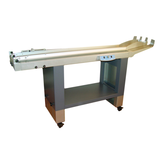
Introduction • 1 Main Components Take a few minutes to become familiar with the components of the belt stacker. Side guides Control panel box Leg assembly Lockable castors Height adjustment knobs (two on each leg) Stacking tray Entry guide (varies with machine configuration) Front end side guide adjustment knobs Rear end side guide adjustment knobs (underneath, not visible) -
Page 12: The Control Panel
1 • Introduction The Control Panel The control panel can be positioned on either side of the stacker, depending on system configuration. To change the position of the control panel, pull the panel firmly towards you to remove it. Refit the control panel to the opening on the opposite side of the belt stacker. -
Page 13: Chapter 2 - Operation
Operation • 2 Use with the Relay 5000/6000/7000/8000 Inserters The belt stacker can be used in Right Angled or In Line configuration with the Relay 5000/6000/7000/8000 Inserters. There are two setups for In Line operation: One for ‘letters’ (e.g. #10, DL/ C5) sized envelopes, and another for ‘flats’ (e.g. #9, C4) sized envelopes. In Line mode is essential for running ‘flats’. Right Angled setup and operation is described below. In Line setup and operation for letters and flats is described later in this chapter. Setup of Right Angled mode with Relay System Inserters The illustration below shows the belt stacker correctly docked to the Relay system inserter in a right angled orientation. - Page 14 2 • Operation 2. Loosen the front and rear end knobs (B) of the side guide closest to the inserter output and move the side guide as far open (in the direction of the arrow) as it will go. Retighten the front and rear end knobs.
-
Page 15: Operation In Right Angled Mode
Operation • 2 5. When positioned correctly, lock all four castors. 6. For right hand operation, the sensor and sensor bracket (D) should be installed as shown in the picture. Make sure there is a spacer (E) between the bracket and stacker side guide at each knob position. For left hand operation the parts are installed mirrored. - Page 16 2 • Operation 5. Set the belt speed to maximum. 6. Start the Relay system. 7. Adjust the envelope overlap by moving the start sensor. When the sensor is moved away from the inlet the distance between the envelopes will be larger, and vice versa. Keep the step as small as possible without envelopes building up too much.
- Page 17 Operation • 2 Setup of In Line mode with Relay Inserters and ‘letter’ sized envelopes The illustration below shows the belt stacker correctly docked to the Relay 5000/6000/7000/8000 Inserter in the In Line orientation running ‘letters’. Use of the stacker in this mode allows the Relay ‘Flats’ box stacker to remain in use as Flats stacker shown.
- Page 18 2 • Operation 2. Check the stacker alignment. It should be level and the height of the stacker belt should be set to correspond with the upper mark on the decal installed to the Inserter exit area. Place a ruler onto the belt, as shown, to aid the height setting.
- Page 19 Operation • 2 Operation in In Line mode with the Relay Inserters (‘letter’ sized envelopes) 1. The stacker side guides will have been locked wide open by your installing engineer as this configuration does not need the side guides to control envelope stacking. 2.
- Page 20 2 • Operation Setup of In Line mode with Relay Inserters and ‘flat’ sized envelopes The illustration below shows the belt stacker correctly docked to the Relay Inserter in the In Line orientation running ‘flats’. Follow the steps to correctly set up the stacker: 1. Check the stacker alignment. It should be level and the height of the stacker belt should be set to correspond with the lower mark on the decal installed...
- Page 21 Operation • 2 2. The sensor should already be installed into the slot on the magnetic bracket. Route the sensor cable back underneath the nuts attached to the sensor body and through the cable cut out on the bracket. Ensure the bottom face of the sensor is as close as possible and parallel to the lower face of the magnetic bracket.
- Page 22 2 • Operation Operation in In Line mode with the Relay Inserters(‘flats’ sized envelopes) 1. The stacker side guides will have been locked wide open by your installing engineer as this configuration does not need the side guides to control envelope stacking. 2.
-
Page 23: Tandem Belt Stacker
Operation • 2 Tandem Belt Stacker A particular configuration of the stacker is available for the Relay Inserters that allows automatic stacking of ‘Letters’ and ‘Flats’ simultaneously. The stacker consists of two stacker units mounted onto one set of legs or one table at the correct vertical spacing to receive ‘Letter’ and ‘Flats’ output from the Inserter. Use the ‘Letters’ In Line instructions in this chapter to setup and operate the top stacker unit. Use the ‘Flats’ In Line instructions for the lower stacker unit. Use of the Belt Stacker with Other Equipment The belt stacker can be used with equipment other than inserters (for example, address printers). -
Page 24: Chapter 3 - Reference
Reference • 3 Troubleshooting Configuration Possible Cause Remedy Envelopes get stuck in the inlet area or feed poorly onto stacker Belt speed too low, Increase belt speed material builds up and gets stuck Step length too small Increase step length Side guides set too narrow Adjust side guides The incoming envelope... -
Page 25: Service
A service maintenance contract is available to keep your belt Stacker (as well as your entire Inserting system) in top condition at nominal cost. Contact Pitney Bowes for details (see the Pitney Bowes Contact List at start of this guide for contact information). -
Page 26: Specifications
Reference • 3 Specifications Equipment Specifications Standard Features Variable speed, Adjustable overlap of media, Clear-deck switch, Universal power inlet, Lockable castors on all four feet, Capacity With a minimum insert in the envelope: 6”X 9” (C5) up to a maximum of 2,500 envelopes 9”X12” (C4) up to a maximum of 1,500 envelopes #10 (DL) up to a maximum of 1,200 envelopes Table Height Adjustable 25”– 42” (635mm –1060mm) (only on models with height adjustable legs) Width 17-1/4” (440mm), incl. 2” (50mm) for control unit... - Page 27 3 • Reference SV40231 Rev. B...
- Page 29 3001 Summer Street Stamford, CT 06926-0700 www.pitneybowes.com SV40231 Rev. B © 2015 Pitney Bowes Inc. All Rights Reserved...
Need help?
Do you have a question about the F680 and is the answer not in the manual?
Questions and answers