Table of Contents
Advertisement
Quick Links
Advertisement
Chapters
Table of Contents

Related Manuals for Pitney Bowes F680


Summary of Contents for Pitney Bowes F680
- Page 1 Conveyor Stacker F680 Operator Guide International English Version...
-
Page 2: Table Of Contents
Contents Before setting up and using the F680, you should be thoroughly familiar with its controls and setup procedure. You should also be thoroughly familiar with each component of the Inserting system the F680 is being used with. This Guide is organised into three chapters: Chapter 1 - Introduction Gives basic details of your Conveyor Stacker. - Page 3 Contents Chapter 2 - Operation Gives the basic steps required to process documents. It explains: Use with the DI500/DI600 Inserters Setup of Right Angled mode ..........Operation in Right Angled mode ........Setup of In Line mode ............Operation in In Line mode ..........Use with the DI800 Inserter Setup of Right Angled mode ..........
- Page 4 Contents Chapter 3 - Reference Covers subjects that may only be required occasionally. It includes: Troubleshooting ..............Service ................Specifications ..............SDC613C...
- Page 5 Contents SDC613C...
-
Page 6: Chapter 1 - Introduction
Introduction • 1 Safety In some countries the equipment is supplied with a moulded mains lead and plug. In other countries, or if the supplied lead is not used, the following information applies: 1. An approved mains lead for the country concerned must be used. -
Page 7: What The Conveyor Stacker Does
1 • Introduction What the Conveyor Stacker Does General The Model F680 Conveyor Stacker is designed as an output device for a range of Inserting Systems and also as a general output device for other machines such as Address Printers. - Page 8 Introduction • 1 The control panel can be positioned on either side of the stacker to accommodate the different configurations possible. It incorporates a variable speed control, run-out button, power switch and power supply. In most cases, the Conveyor Stacker is mounted on height adjustable legs.
-
Page 9: Main Components
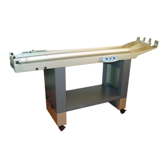
1 • Introduction Main Components Take a few minutes to become familiar with the components of the Conveyor Stacker. Side guides Control panel box Leg assembly Lockable castors Height adjustment knobs (two on each leg) Stacking tray Entry guide (varies with machine configuration) Front end side guide adjustment knobs Rear end side guide adjustment knobs (underneath, not visible) -
Page 10: The Control Panel
Introduction • 1 The Control Panel The control panel can be positioned on either side of the stacker, depending on system configuration. To change the position of the control panel, pull the panel firmly towards you to remove it. Refit the control panel to the opening on the opposite side of the Conveyor Stacker. - Page 11 1 • Introduction SDC613B SDC613C...
-
Page 12: Chapter 2 - Operation
Operation • 2 Use with DI500/DI600 Inserters The Conveyor Stacker can be used in Right Angled or In Line configuration with the DI500/DI600 Inserters. Right Angled setup and operation is described below. In Line setup and operation is described on page 2-4. Setup of Right Angled mode with DI500/DI600 Inserters The illustration below shows the Conveyor Stacker correctly docked to the DI500/DI600 Inserter in a right angled orientation. -
Page 13: Operation In Right Angled Mode
2 • Operation 3. Position the Conveyor Stacker Inserter output level or with the side guide under the just overlapping guide Inserter output as shown. Make sure the Inserter output is level with or just overlapping the guide. 4. Lock all four castors. 5. - Page 14 Operation • 2 3. Adjust the side guide to give a 3mm clearance clearance of about 3mm and retighten the front and rear end side guide knobs. Make sure the side guides are parallel! 4. Read the safety information on page 1-1, then connect the Conveyor Stacker to the mains supply and turn ON.
-
Page 15: Setup Of In Line Mode
2 • Operation Setup of In Line mode with DI500/DI600 Inserters The illustration below shows the Conveyor Stacker correctly docked to the DI500/DI600 Inserter in an in line orientation. Follow the steps to correctly set up the Stacker: 1. Check the Stacker alignment. It should be level and the stacker belt should be 100mm to 110mm below the Inserter output slot. -
Page 16: Operation In In Line Mode
Operation • 2 3. Position the Stacker against the output end of the Inserter, centred with the output. Make sure the Stacker is positioned slightly under the inserter output as shown. 4. When positioned correctly, lock all four castors. Operation in In Line mode with DI500/DI600 Inserters 1. -
Page 17: Use With The Di800 Inserter
2 • Operation Use with the DI800 Inserter The Conveyor Stacker can be used in Right Angled or In Line configuration with the DI800 Inserter. In Line mode is preferred for running heavy, large envelopes. Right Angled setup and operation is described below. In Line setup and operation is described on page 2-9. - Page 18 Operation • 2 2. Loosen the front and rear end knobs (B) of the side guide closest to the inserter output and move the side guide as close as possible to the inserter. Retighten the front and rear end knobs. 3.
-
Page 19: Operation In Right Angled Mode
2 • Operation Operation in Right Angled mode with the DI800 Inserter 1. Place one envelope on the belt. 3mm clearance 2. Loosen the front and rear end side guide knobs (A) of the side guide with the sensor bracket only. -
Page 20: Setup Of In Line Mode
Operation • 2 8. Reduce the belt speed until the motor runs continuously. Setup of In Line mode with the DI800 Inserter The illustration below shows the Conveyor Stacker correctly docked to the DI800 Inserter in the In Line orientation. Follow the steps to correctly set up the Stacker: 1. -
Page 21: Position The Stacker Against
2 • Operation 2. The in line idler rollers (B) and sensor bracket (C) will have been installed as shown in the illustration. 3. Position the Stacker as illustrated. The upper outer corner of the sensor side guide should be aligned with the lower left output corner of the Inserter. -
Page 22: Operation In In Line Mode
Operation • 2 Operation in In Line mode with the DI800 Inserter 1. Set the side guides for the material being used: Basic setting for side guides for DL size envelopes: Basic setting of side guides for C5 size envelopes: Only the side guide without the sensor needs to be moved when changing format. - Page 23 2 • Operation 6. Adjust the envelope overlap by moving the start sensor. When the sensor is moved away from the inlet the distance between the envelopes will be larger, and vice versa. (Illustrations below show sensor setting with idler wheels removed for clarity). Keep the step as small as possible without envelopes building up too much.
-
Page 24: Use With The Di875 Inserter
Operation • 2 Use with the DI875 Inserter The Conveyor Stacker can be used in Right Angled or In Line configuration with the DI875 Inserter. In Line mode is preferred for running heavy, large envelopes. Right Angled setup and operation is described below, In Line setup and operation is described on page 2-17. - Page 25 2 • Operation 3. Check the Stacker alignment. Docking studs It should be level and, when positioned against the Inserter, the docking studs on the Stacker should fit into the cut-out on the Cut-out Inserter. If not correct, loosen the height adjustment knobs (A) on each leg in turn and readjust the Stacker height.
-
Page 26: Operation In Right Angled Mode
Operation • 2 Operation in Right Angled mode with the DI875 Inserter 1. Place one envelope on the belt. 3mm clearance 2. Loosen the front and rear end side guide knobs (A) of the side guide with the sensor bracket only. -
Page 27: Reduce The Belt Speed Until The Motor Runs Continuously
2 • Operation 7. Start the DI875 system. 8. Adjust the envelope overlap by moving the start sensor. When the sensor is moved away from the inlet the distance between the envelopes will be larger, and vice versa. Keep the step as small as possible without envelopes building up too much. -
Page 28: Setup Of In Line Mode
Operation • 2 Setup of In Line mode with the DI875 Inserter The illustration below shows the Conveyor Stacker correctly docked to the DI875 Inserter in the In Line orientation. Follow the steps to correctly set up the Stacker: 1. The in line idler rollers (A) and sensor bracket (B) will have been installed as shown in the illustration. -
Page 29: Operation In In Line Mode
2 • Operation If not correct, loosen the height adjustment knobs (C) on each leg in turn and readjust the Stacker height. 3. Position the Stacker as close to the Inserter output as possible and centred with the output. When positioned correctly, lock all four castors. - Page 30 Operation • 2 4. Read the safety information on page 1-1, then connect the Conveyor Stacker to the mains supply and turn ON. 5. Set the belt speed to maximum. 6. Start the DI875 system. 7. Adjust the envelope overlap by moving the start sensor. When the sensor is moved away from the inlet the distance between the envelopes will be larger, and vice versa.
-
Page 31: Use With The Di900/Di950 Inserters
2 • Operation Use with the DI900/DI950 Inserters The Conveyor Stacker can be used in Right Angled or In Line configuration with the DI900/DI950 Inserters. There are two setups for In Line operation: One for ‘letters’ (e.g. DL/C5) sized envelopes, and another for ‘flats’ (e.g. C4) sized envelopes. - Page 32 Operation • 2 2. Loosen the front and rear end knobs (B) of the side guide closest to the inserter output and move the side guide as far open (in the direction of the arrow) as it will go. Retighten the front and rear end knobs.
-
Page 33: Operation In Right Angled Mode
2 • Operation 5. When positioned correctly, lock all four castors. 6. For right hand operation, the sensor and sensor bracket (D) should be installed as shown in the picture. Make sure there is a spacer (E) between the bracket and Stacker side guide at each knob position. - Page 34 Operation • 2 5. Set the belt speed to maximum. 6. Start the DI900/DI950 system. 7. Adjust the envelope overlap by moving the start sensor. When the sensor is moved away from the inlet the distance between the envelopes will be larger, and vice versa. Keep the step as small as possible without envelopes building up too much.
- Page 35 2 • Operation Setup of In Line mode with DI900/DI950 Inserters and ‘letter’ sized envelopes The illustration below shows the Conveyor Stacker correctly docked to the DI900/DI950 Inserter in the In Line orientation running ‘letters’. Use of the Stacker in this mode allows the DI900/DI950 ‘Flats’...
- Page 36 Operation • 2 2. Check the Stacker alignment. It should be level and the height of the Stacker belt should be set to correspond with the upper mark on the decal fitted to the Inserter exit area. Place a ruler onto the belt, as shown, to aid the height setting.
- Page 37 2 • Operation Operation in In Line mode with the DI900/DI950 Inserters (‘letter’ sized envelopes) 1. The Stacker side guides will have been locked wide open by your installing engineer as this configuration does not need the side guides to control envelope stacking. 2.
- Page 38 Operation • 2 Setup of In Line mode with DI900/DI950 Inserters and ‘flat’ sized envelopes The illustration below shows the Conveyor Stacker correctly docked to the DI900/DI950 Inserter in the In Line orientation running ‘flats’. Follow the steps to correctly set up the Stacker: 1.
- Page 39 2 • Operation 2. The sensor should already be fitted the sensor into the slot on the magnetic bracket. Route the sensor cable back underneath the nuts attached to the sensor body and through the cable cut out on the bracket. Ensure the bottom face of the sensor is as close as possible and parallel to the lower face of...
- Page 40 Operation • 2 Operation in In Line mode with the DI900/DI950 Inserters (‘flats’ sized envelopes) 1. The Stacker side guides will have been locked wide open by your installing engineer as this configuration does not need the side guides to control envelope stacking. 2.
- Page 41 2 • Operation The Two-tier Stacker A particular configuration of the Stacker is available for the DI900/ DI950 Inserters that allows automatic stacking of ‘Letters’ and ‘Flats’ simultaneously. The Stacker consists of two stacker units mounted onto one set of legs or one table at the correct vertical spacing to receive ‘Letter’...
- Page 42 Reference • 3 Troubleshooting Configuration Possible Cause Remedy Envelopes get stuck in the inlet area or feed poorly onto stacker Belt speed too low, Increase belt speed material builds up and gets stuck Step length too small Increase step length Side guides set too narrow Adjust side guides The incoming envelope...
- Page 43 3 • Reference Configuration Possible Cause Remedy Envelopes hit sensor bracket Right angled Rear (sensor) guide set too Move rear (sensor) guide configurations close to inserter back DI900/DI950 Adjustable sensor bracket Pivot sensor bracket In line ‘Letters’ too close to inserter slightly further back Material doesn’t transport all the way to the stacker end stacking tray Side guides too narrow or...
- Page 44 Reference • 3 Specifications Equipment Specifications: Standard Features Variable speed, Adjustable overlap of media, Clear-deck switch, Universal power inlet, Lockable castors on all four feet, Aligning studs for Inserter DI875 Capacity With a minimum insert in the envelope: C4 up to a maximum of 1,500 envelopes C5 up to a maximum of 2,500 envelopes DL up to a maximum of 1,200 envelopes Table Height...
- Page 45 3 • Reference SDC613C SDC613B...
- Page 46 For Service and Supplies PB Form SDC613C (9-22) © Pitney Bowes Limited, 2022 We have made every reasonable effort to assure the accuracy and usefulness of this guide, however we cannot assume responsibility for errors or omissions or liability for the misuse or misapplication of our products.
Need help?
Do you have a question about the F680 and is the answer not in the manual?
Questions and answers